DE102009055969A1 - Device and set for folding or unfolding a medical implant and method - Google Patents
Device and set for folding or unfolding a medical implant and methodDownload PDFInfo
- Publication number
- DE102009055969A1 DE102009055969A1DE102009055969ADE102009055969ADE102009055969A1DE 102009055969 A1DE102009055969 A1DE 102009055969A1DE 102009055969 ADE102009055969 ADE 102009055969ADE 102009055969 ADE102009055969 ADE 102009055969ADE 102009055969 A1DE102009055969 A1DE 102009055969A1
- Authority
- DE
- Germany
- Prior art keywords
- shaft
- sleeve
- tensioning
- implant
- thread
- Prior art date
- Legal status (The legal status is an assumption and is not a legal conclusion. Google has not performed a legal analysis and makes no representation as to the accuracy of the status listed.)
- Ceased
Links
- 239000007943implantSubstances0.000titleclaimsabstractdescription75
- 238000000034methodMethods0.000titleclaimsabstractdescription13
- 210000003709heart valveAnatomy0.000claimsdescription2
- 238000002513implantationMethods0.000description9
- 230000008901benefitEffects0.000description4
- 230000001681protective effectEffects0.000description4
- 230000007704transitionEffects0.000description4
- 230000008859changeEffects0.000description3
- 239000012530fluidSubstances0.000description3
- 230000009286beneficial effectEffects0.000description2
- 230000005540biological transmissionEffects0.000description2
- 239000000463materialSubstances0.000description2
- 238000003825pressingMethods0.000description2
- 230000009471actionEffects0.000description1
- 230000001419dependent effectEffects0.000description1
- 238000011161developmentMethods0.000description1
- 230000018109developmental processEffects0.000description1
- 230000000694effectsEffects0.000description1
- 238000003780insertionMethods0.000description1
- 230000037431insertionEffects0.000description1
- 230000009467reductionEffects0.000description1
- 238000000926separation methodMethods0.000description1
- 230000008093supporting effectEffects0.000description1
Images


Classifications
- A—HUMAN NECESSITIES
- A61—MEDICAL OR VETERINARY SCIENCE; HYGIENE
- A61F—FILTERS IMPLANTABLE INTO BLOOD VESSELS; PROSTHESES; DEVICES PROVIDING PATENCY TO, OR PREVENTING COLLAPSING OF, TUBULAR STRUCTURES OF THE BODY, e.g. STENTS; ORTHOPAEDIC, NURSING OR CONTRACEPTIVE DEVICES; FOMENTATION; TREATMENT OR PROTECTION OF EYES OR EARS; BANDAGES, DRESSINGS OR ABSORBENT PADS; FIRST-AID KITS
- A61F2/00—Filters implantable into blood vessels; Prostheses, i.e. artificial substitutes or replacements for parts of the body; Appliances for connecting them with the body; Devices providing patency to, or preventing collapsing of, tubular structures of the body, e.g. stents
- A61F2/02—Prostheses implantable into the body
- A61F2/24—Heart valves ; Vascular valves, e.g. venous valves; Heart implants, e.g. passive devices for improving the function of the native valve or the heart muscle; Transmyocardial revascularisation [TMR] devices; Valves implantable in the body
- A61F2/2427—Devices for manipulating or deploying heart valves during implantation
- A61F2/2439—Expansion controlled by filaments
- A—HUMAN NECESSITIES
- A61—MEDICAL OR VETERINARY SCIENCE; HYGIENE
- A61F—FILTERS IMPLANTABLE INTO BLOOD VESSELS; PROSTHESES; DEVICES PROVIDING PATENCY TO, OR PREVENTING COLLAPSING OF, TUBULAR STRUCTURES OF THE BODY, e.g. STENTS; ORTHOPAEDIC, NURSING OR CONTRACEPTIVE DEVICES; FOMENTATION; TREATMENT OR PROTECTION OF EYES OR EARS; BANDAGES, DRESSINGS OR ABSORBENT PADS; FIRST-AID KITS
- A61F2/00—Filters implantable into blood vessels; Prostheses, i.e. artificial substitutes or replacements for parts of the body; Appliances for connecting them with the body; Devices providing patency to, or preventing collapsing of, tubular structures of the body, e.g. stents
- A61F2/95—Instruments specially adapted for placement or removal of stents or stent-grafts
- A—HUMAN NECESSITIES
- A61—MEDICAL OR VETERINARY SCIENCE; HYGIENE
- A61F—FILTERS IMPLANTABLE INTO BLOOD VESSELS; PROSTHESES; DEVICES PROVIDING PATENCY TO, OR PREVENTING COLLAPSING OF, TUBULAR STRUCTURES OF THE BODY, e.g. STENTS; ORTHOPAEDIC, NURSING OR CONTRACEPTIVE DEVICES; FOMENTATION; TREATMENT OR PROTECTION OF EYES OR EARS; BANDAGES, DRESSINGS OR ABSORBENT PADS; FIRST-AID KITS
- A61F2/00—Filters implantable into blood vessels; Prostheses, i.e. artificial substitutes or replacements for parts of the body; Appliances for connecting them with the body; Devices providing patency to, or preventing collapsing of, tubular structures of the body, e.g. stents
- A61F2/02—Prostheses implantable into the body
- A61F2/24—Heart valves ; Vascular valves, e.g. venous valves; Heart implants, e.g. passive devices for improving the function of the native valve or the heart muscle; Transmyocardial revascularisation [TMR] devices; Valves implantable in the body
- A61F2/2412—Heart valves ; Vascular valves, e.g. venous valves; Heart implants, e.g. passive devices for improving the function of the native valve or the heart muscle; Transmyocardial revascularisation [TMR] devices; Valves implantable in the body with soft flexible valve members, e.g. tissue valves shaped like natural valves
- A—HUMAN NECESSITIES
- A61—MEDICAL OR VETERINARY SCIENCE; HYGIENE
- A61F—FILTERS IMPLANTABLE INTO BLOOD VESSELS; PROSTHESES; DEVICES PROVIDING PATENCY TO, OR PREVENTING COLLAPSING OF, TUBULAR STRUCTURES OF THE BODY, e.g. STENTS; ORTHOPAEDIC, NURSING OR CONTRACEPTIVE DEVICES; FOMENTATION; TREATMENT OR PROTECTION OF EYES OR EARS; BANDAGES, DRESSINGS OR ABSORBENT PADS; FIRST-AID KITS
- A61F2/00—Filters implantable into blood vessels; Prostheses, i.e. artificial substitutes or replacements for parts of the body; Appliances for connecting them with the body; Devices providing patency to, or preventing collapsing of, tubular structures of the body, e.g. stents
- A61F2/95—Instruments specially adapted for placement or removal of stents or stent-grafts
- A61F2002/9505—Instruments specially adapted for placement or removal of stents or stent-grafts having retaining means other than an outer sleeve, e.g. male-female connector between stent and instrument
- A61F2002/9511—Instruments specially adapted for placement or removal of stents or stent-grafts having retaining means other than an outer sleeve, e.g. male-female connector between stent and instrument the retaining means being filaments or wires
Landscapes
- Health & Medical Sciences (AREA)
- Cardiology (AREA)
- Engineering & Computer Science (AREA)
- Biomedical Technology (AREA)
- Heart & Thoracic Surgery (AREA)
- Transplantation (AREA)
- Oral & Maxillofacial Surgery (AREA)
- Vascular Medicine (AREA)
- Life Sciences & Earth Sciences (AREA)
- Animal Behavior & Ethology (AREA)
- General Health & Medical Sciences (AREA)
- Public Health (AREA)
- Veterinary Medicine (AREA)
- Prostheses (AREA)
Abstract
Translated fromGermanDescription
Translated fromGermanDie vorliegende Erfindung betrifft eine Vorrichtung gemäß Anspruch 1 zum Falten oder Entfalten eines Implantats, und ein Set gemäß Anspruch 17. Sie betrifft ferner ein Verfahren gemäß Anspruch 18.The present invention relates to an apparatus according to
Aus der Praxis sind Implantate bekannt, welche mittels eines oder mehrere Fäden, über welche Spannung auf das Implantat übertragen wird, gefaltet und/oder entfaltet werden können. Aus der Praxis sind zum Falten und Entfalten ferner entsprechende Vorrichtungen bekannt.Implants are known in practice, which can be folded and / or unfolded by means of one or more threads, via which tension is transferred to the implant. From practice, corresponding devices are also known for folding and unfolding.
Eine Aufgabe der vorliegenden Erfindung ist, eine Vorrichtung zum Falten oder Entfalten eines faltbaren und/oder entfaltbaren Implantats mittels eines Spannfadens vorzuschlagen. Ferner soll ein geeignetes Set mit einer solchen Vorrichtung, ein Verfahren zum Falten und/oder Entfalten eines Implantats sowie ein Verfahren zum Durchtrennen eines Spannfadens angegeben werden.An object of the present invention is to propose a device for folding or unfolding a foldable and / or deployable implant by means of a tensioning thread. Furthermore, a suitable set with such a device, a method for folding and / or unfolding an implant and a method for severing a tensioning thread should be specified.
Diese Aufgabe wird durch eine Vorrichtung mit den Merkmalen des Anspruchs 1 gelöst.This object is achieved by a device having the features of
So wird erfindungsgemäß eine Vorrichtung zum Einbringen, und/oder Falten und/oder Entfalten eines Implantats mittels wenigstens eines Spannfadens vorgeschlagen. Die erfindungsgemäße Vorrichtung weist einen Schaft mit einem Aufnahmebereich zum Aufnehmen des Implantats auf.Thus, the invention proposes a device for introducing, and / or folding and / or unfolding an implant by means of at least one tensioning thread. The device according to the invention has a shaft with a receiving area for receiving the implant.
Die Vorrichtung weist ferner wenigstens eine Spanneinrichtung zum Verändern einer Gestalt des falt- und/oder entfaltbaren Implantats mittels des Spannfadens auf.The device further comprises at least one clamping device for changing a shape of the foldable and / or deployable implant by means of the tensioning thread.
Die Vorrichtung weist zudem eine Trenneinrichtung auf zum Trennen wenigstens eines Spannfadens vom Implantat und/oder zum Durchtrennen des Spannfadens.The device also has a separating device for separating at least one tensioning thread from the implant and / or for severing the tensioning thread.
Vorteilhafte Weiterentwicklungen der erfindungsgemäßen Vorrichtung sind jeweils Gegenstand der Unteransprüche.Advantageous developments of the device according to the invention are the subject of the dependent claims.
In einer Ausführungsform der erfindungsgemäßen Vorrichtung ist das verändern einer Gestalt des Implantats ein Verringern oder Vergrößern eines Durchmessers, insbesondere ein äußerer Durchmesser, des Implantats. Dabei kann eine Veränderung der Länge des Implantats oder eine sonstige Veränderung mit einhergehen oder nicht.In one embodiment of the device according to the invention, changing a shape of the implant is reducing or increasing a diameter, in particular an outer diameter, of the implant. It may be accompanied by a change in the length of the implant or any other change or not.
In einer Ausführungsform der erfindungsgemäßen Vorrichtung ist das Falten des Implantats ein Verringern eines Durchmessers des Implantats.In one embodiment of the device according to the invention, the folding of the implant is a reduction of a diameter of the implant.
Das Entfalten ist in erfindungsgemäßen Ausführungsformen als ein Vergrößern eines Durchmessers des Implantats zu verstehen.Unfolding is understood in embodiments of the invention to be an enlargement of a diameter of the implant.
Der Durchmesser des Implantats steht in einer erfindungsgemäßen Ausführungsform in einer Ebene senkrecht zu einer Hauptdurchströmungsrichtung des Implantats, falls dieses Implantat nach Implantierung von einem Fluid durchströmt wird.The diameter of the implant is in an embodiment of the invention in a plane perpendicular to a main flow direction of the implant, if this implant is perfused after implantation of a fluid.
In einer Ausführungsform der erfindungsgemäßen Vorrichtung ist der wenigstens eine Spannfaden ein Faden. Er kann ähnlich einem chirurgischen Nahtfaden ausgestaltet sein. Er kann als ein Seil oder als eine Schnur ausgestaltet sein. Er kann als eine Kette mit einer Mehrzahl von ineinander greifenden Gliedern ausgestaltet sein.In one embodiment of the device according to the invention, the at least one tensioning thread is a thread. It can be configured similarly to a surgical suture thread. It can be configured as a rope or as a string. It can be configured as a chain with a plurality of interlocking links.
Wenn im Folgenden von einem Faden oder Spannfaden die Rede ist, können immer auch eine Mehrzahl von Fäden oder Spannfäden gemeint sein, sofern der Fachmann die Austauschbarkeit der Begriffe erkennt.Whenever a thread or tensioning thread is mentioned below, a plurality of threads or tensioning threads can always be meant, provided that the person skilled in the art recognizes the interchangeability of the concepts.
In bestimmten Ausführungsformen ist der Schaft der Vorrichtung starr ausgeführt. In manchen Ausführungsformen ist der Schaft der Vorrichtung in eine oder mehrere Richtungen biegbar ausgeführt (d. h. er kann in einer Längsrichtung oder in einer Richtung der Breite des Schafts, in beiden Richtung oder in einer anderen Richtungen gebogen werden). In manchen Ausführungsformen ist der Schaft streckbar ausgestaltet. In anderen Ausführungsformen ist der Schaft steif ausgestaltet.In certain embodiments, the shaft of the device is rigid. In some embodiments, the shaft of the device is bendable in one or more directions (i.e., it can be bent in a longitudinal direction or in a width direction of the shaft, in either direction, or in other directions). In some embodiments, the shaft is stretchable. In other embodiments, the shaft is stiff.
In einer Ausführungsform der erfindungsgemäßen Vorrichtung ist das Implantat in seinem Implantationszustand in seiner Längsrichtung für Fluide durchgängig. Der Begriff „durchgängig” bezeichnet hierbei das Vermögen des Implantats, von Fluiden durchströmt zu werden.In one embodiment of the device according to the invention, the implant is continuous in its implantation state in its longitudinal direction for fluids. The term "continuous" here refers to the ability of the implant to be flowed through by fluids.
In einer Ausführungsform der erfindungsgemäßen Vorrichtung ist das Implantat im Moment seines Entfaltens oder Faltens auf oder an dem Aufnahmebereich der Vorrichtung – zumindest vorübergehend – locker angeordnet oder befestigt.In one embodiment of the device according to the invention, at the moment of its unfolding or folding on or at the receiving area of the device, the implant is loosely arranged or fastened - at least temporarily.
In einer Ausführungsform der erfindungsgemäßen Vorrichtung weist die Spanneinrichtung wenigstens eine Zugeinrichtung auf. Die Zugeinrichtung ist angeordnet und/oder vorgesehen, um mittels des Spannfadens – mittelbar oder unmittelbar – eine Spannung auf das Implantat zum Verändern der Gestalt des Implantats aufzubringen.In one embodiment of the device according to the invention, the clamping device has at least one pulling device. The pulling device is arranged and / or provided to apply a tension to the implant for changing the shape of the implant by means of the tensioning thread, directly or indirectly.
Alternativ oder ergänzend ist die Zugeinrichtung in einer Ausführungsform der erfindungsgemäßen Vorrichtung angeordnet und/oder vorgesehen, um eine mittels des Spannfadens auf das Implantat aufgebrachte Spannung zu verringern.Alternatively or additionally, the traction device is arranged and / or provided in an embodiment of the device according to the invention, to reduce a tension applied to the implant by means of the tensioning thread.
In einer Ausführungsform der erfindungsgemäßen Vorrichtung ist die Zugeinrichtung angeordnet und/oder vorgesehen, um mit dem Spannfaden zum Übertragen von Kraft oder Spannung zusammen zu wirken.In one embodiment of the device according to the invention, the pulling device is arranged and / or provided to cooperate with the tensioning thread for transmitting force or tension.
In einer Ausführungsform der erfindungsgemäßen Vorrichtung sind die Zugeinrichtung und der Spannfaden miteinander verschlungen.In one embodiment of the device according to the invention, the traction device and the tensioning thread are entangled with each other.
Unter „verschlungen” wird in einer erfindungsgemäßen Ausführungsform verstanden, dass der Spannfaden relativ zur Zugeinrichtung in wenigstens einer Raumrichtung oder in zwei Raumrichtungen verschiebbar ist.In an embodiment according to the invention, "intertwined" is understood to mean that the tensioning thread is displaceable relative to the pulling device in at least one spatial direction or in two spatial directions.
Unter „verschiebbar” kann erfindungsgemäß auch „gleitbar” zu verstehen sein.The term "displaceable" may also be understood to mean "slidable" according to the invention.
Unter „verschlungen” wird in einer erfindungsgemäßen Ausführungsform verstanden, dass der Spannfaden relativ zur Zugeinrichtung wie ein erstes Glied einer Kette relativ zu einem benachbarten zweiten Glied dieser Kette, mit welchem das erste Glied in bei einer Kette üblich verbunden ist, bewegbar angeordnet ist.By "entangled" in an embodiment according to the invention is meant that the tensioning thread is arranged to be movable relative to the pulling device like a first link of a chain relative to an adjacent second link of this chain, with which the first link is usually connected in a chain.
Unter „verschlungen” wird in einer erfindungsgemäßen Ausführungsform verstanden, dass der Spannfaden mit der Zugeinrichtung oder Abschnitten hiervon auf einfache Weise einmal überkreuzt ist.In an embodiment according to the invention, "intertwined" is understood to mean that the tensioning thread is crossed once in a simple manner with the pulling device or sections thereof.
Das Übertragen von Kraft oder Spannung zwischen der Zugeinrichtung und dem Spannfaden erfolgt in einer erfindungsgemäßen Ausführungsform mittels einer nicht formschlüssigen Verbindung.The transmission of force or tension between the traction device and the tensioning thread takes place in an embodiment according to the invention by means of a non-positive connection.
In einer erfindungsgemäßen Ausführungsform erfolgt das Übertragen von Kraft oder Spannung zwischen der Zugeinrichtung und dem Spannfaden mittels einer kraftschlüssigen Verbindung.In one embodiment according to the invention, the transmission of force or tension between the pulling device and the tensioning thread takes place by means of a non-positive connection.
In einer Ausführungsform der erfindungsgemäßen Vorrichtung ist die Zugeinrichtung als wenigstens ein Zugfaden ausgestaltet oder besteht aus wenigstens einem Zugfaden.In one embodiment of the device according to the invention, the pulling device is configured as at least one pulling thread or consists of at least one pulling thread.
In einer Ausführungsform der erfindungsgemäßen Vorrichtung weist der Spannfaden und/oder der Zugfaden ein Bündel oder eine Mehrzahl von Fäden oder Fadenelementen auf oder besteht hieraus.In one embodiment of the device according to the invention, the tensioning thread and / or the pulling thread comprises or consists of a bundle or a plurality of threads or thread elements.
In einer Ausführungsform der erfindungsgemäßen Vorrichtung weist die Trenneinrichtung wenigstens eine Schneideeinrichtung zum Durchschneiden des Spannfadens auf oder besteht aus dieser.In one embodiment of the device according to the invention, the separating device has at least one cutting device for cutting through the tensioning thread or consists of this.
In einer erfindungsgemäßen Ausführungsform weist die Vorrichtung eine Hülse auf. Die Hülse kann rohrartig (also innen hohl), wie ein Hohlzylinder, wie ein Ring oder dergleichen ausgestaltet sein. Die Hülse kann symmetrisch oder unsymmetrisch ausgestaltet sein, sowohl bezogen auf ihre Durchgangsrichtung als auch in einer anderen Richtung, insbesondere in einer Richtung oder Ebene senkrecht zur Durchgangsrichtung.In an embodiment according to the invention, the device has a sleeve. The sleeve may be tube-like (ie hollow inside), such as a hollow cylinder, such as a ring or the like configured. The sleeve may be configured symmetrically or asymmetrically, both in terms of their passage direction and in another direction, in particular in a direction or plane perpendicular to the passage direction.
In einer Ausführungsform der erfindungsgemäßen Vorrichtung ist die Trenneinrichtung als Teil einer Hülsenöffnung in einer Wandung der Hülse der Vorrichtung ausgestaltet. Die Hülsenöffnung verbindet in einer Ausführungsform der erfindungsgemäßen Vorrichtung ein Äußeres der Hülse mit einem Inneren der Hülse.In one embodiment of the device according to the invention, the separating device is designed as part of a sleeve opening in a wall of the sleeve of the device. The sleeve opening connects in an embodiment of the device according to the invention an exterior of the sleeve with an interior of the sleeve.
Sie ist in dieser Ausführungsform als Durchgangsöffnung ausgestaltet und kann in radialer Richtung der Vorrichtung damit etwa die Dicke der Wandung der Hülse haben.It is designed in this embodiment as a passage opening and can thus have approximately the thickness of the wall of the sleeve in the radial direction of the device.
In einer Ausführungsform der erfindungsgemäßen Vorrichtung weist die Hülsenöffnung wenigstens eine erste Vertiefung auf. Durch die erste Vertiefung kann wenigstens ein Spannfaden geführt werden.In one embodiment of the device according to the invention, the sleeve opening has at least one first recess. At least one tensioning thread can be guided through the first recess.
In einer Ausführungsform der erfindungsgemäßen Vorrichtung weist die erste Vertiefung einen ersten Bereich mit einer Schneideeinrichtung zum Durchtrennen des Spannfadens auf.In one embodiment of the device according to the invention, the first recess has a first region with a cutting device for severing the tensioning thread.
In bestimmten Ausführungsformen ist die Schneideeinrichtung ein Schneidmesser oder weist ein solches auf. In manchen Ausführungsformen ist die Schneideeinrichtung an der Hülse befestigt. In manchen Ausführungsformen ist die Schneideeinrichtung in die Hülse integriert.In certain embodiments, the cutting device is or has a cutting blade. In some embodiments, the cutter is attached to the sleeve. In some embodiments, the cutting device is integrated in the sleeve.
In einer Ausführungsform der erfindungsgemäßen Vorrichtung weist die erste Vertiefung einen zweiten Bereich ohne eine Schneideeinrichtung auf.In one embodiment of the device according to the invention, the first recess has a second area without a cutting device.
In einer Ausführungsform der erfindungsgemäßen Vorrichtung weist die Hülsenöffnung wenigstens eine zweite Vertiefung auf, in welcher – wie bei der ersten Vertiefung – wenigstens ein Spannfaden geführt werden kann.In one embodiment of the device according to the invention, the sleeve opening has at least one second recess, in which - as in the first recess - at least one tensioning thread can be guided.
Dabei können die erste Vertiefung und die zweite Vertiefung derart von einem Steg getrennt sein, dass wenigstens zwei Spannfäden mit Abstand zueinander in den Vertiefungen geführt werden können.In this case, the first recess and the second recess can be separated from a web in such a way that at least two tensioning threads can be guided at a distance from one another in the recesses.
Ein Abstand zwischen den beiden Vertiefungen kann ein Führen von zwei oder mehr Spannfäden, welche auf die beiden Vertiefungen verteilt sind, ermöglichen, ohne dass sich diese im Bereich der Vertiefungen berühren. Damit ist ein Führen von mehreren Spannfäden durch eine Hülsenöffnung vorteilhaft möglich, ohne dass sich die Spannfäden gegenseitig behindern müssen. Zudem erlaubt das getrennte Führen von Spannfäden, welches durch das Vorsehen mehrerer Vertiefungen begünstigt wird, auf vorteilhafte Weise eine getrennte Behandlung oder Verwendung der einzelnen Spannfäden: eine Behandlung oder Verwendung der Spannfäden, welche durch eine erste Vertiefung führen, kann sich damit von einer Behandlung oder Verwendung der Spannfäden, welche durch eine zweite Vertiefung führen, vorteilhaft unterscheiden.A distance between the two recesses may be a guiding of two or more tensioning threads, which are distributed over the two recesses are possible without these touching each other in the area of the recesses. Thus, a guiding of a plurality of tensioning threads through a sleeve opening is advantageously possible without the tensioning threads having to hinder each other. In addition, the separate guiding of tensioning threads, which is favored by the provision of several depressions, advantageously allows a separate treatment or use of the individual tensioning threads: a treatment or use of the tensioning threads, which lead through a first depression, can thus result from a treatment or Use of the tensioning threads, which lead through a second recess, advantageously distinguish.
In einer Ausführungsform der erfindungsgemäßen Vorrichtung ist der Steg kann Teil der Hülse. Der Steg ist somit Teil der Wandung der Hülse und/oder integral mit dieser hergestellt.In one embodiment of the device according to the invention, the web can be part of the sleeve. The web is thus part of the wall of the sleeve and / or produced integrally therewith.
Die beiden oben genannten Vertiefungen (was auch für dritte, vierte und weitere Vertiefungen gelten kann) können auch als Nischen, als Erstreckungen, als Ausbuchtungen, als Verzweigungen, als Aussparungen und dergleichen bezeichnet werden. Diesen Begriffen ist in einer erfindungsgemäßen Ausführungsform gemeinsam, dass die Vertiefungen, Nischen oder dergleichen von einem gemeinsamen, insbesondere weiten, Bereich der Hülsenöffnung abgehen oder mit diesem in Verbindung stehen.The two recesses mentioned above (which may also apply to third, fourth and further depressions) may also be referred to as niches, as extensions, as bulges, as branches, as recesses and the like. These terms are common in one embodiment according to the invention that the depressions, recesses or the like depart from a common, in particular wide, region of the sleeve opening or are in connection therewith.
In einer Ausführungsform der erfindungsgemäßen Vorrichtung weist wenigstens die erste Vertiefung (oder eine beliebige Vertiefung) eine Erstreckung in einer Dimension der Vorrichtung (vorzugsweise in eine longitudinalen Erstreckung der Vorrichtung) auf, welche sich von einer Erstreckung wenigstens der zweiten Vertiefung in derselben Dimension der Vorrichtung unterscheidet.In one embodiment of the device according to the invention, at least the first recess (or any recess) has an extension in one dimension of the device (preferably in a longitudinal extension of the device), which differs from an extension of at least the second recess in the same dimension of the device ,
Der Schaft der Vorrichtung ist in einer erfindungsgemäße Ausführungsform in seinem Inneres wenigstens in Abschnitten seiner Längsrichtung durchgängig. Der Schaft weist eine Wandung auf. Der Schaft weist wenigstens eine Schaftöffnung auf. Die wenigstens eine Schaftöffnung ist vorzugsweise nicht an der Stirnseite, sondern an einer Mantelfläche des Schafts angeordnet.The shaft of the device is in an embodiment of the invention in its interior at least in sections of its longitudinal direction through. The shaft has a wall. The shaft has at least one shaft opening. The at least one shaft opening is preferably not arranged on the front side, but on a lateral surface of the shaft.
Der Schaft der Vorrichtung weist in einer erfindungsgemäße Ausführungsform eine Mehrzahl von Schaftöffnungen auf, welche um einen Umfang oder über eine Mantelfläche des Schafts gleichmäßig oder ungleichmäßig verteilt sind. Zusätzlich oder alternativ dazu können die Schaftöffnungen über eine Längsrichtung des Schafts verteilt sein.The shaft of the device in an embodiment according to the invention has a plurality of shaft openings which are distributed uniformly or non-uniformly around a circumference or over a lateral surface of the shaft. Additionally or alternatively, the shaft openings may be distributed over a longitudinal direction of the shaft.
Durch die Schaftöffnung können Spannfäden zum Falten und/oder Entfalten des Implantats ein- und/oder austreten. Die Hülse ist im Gebrauchszustand der Vorrichtung in einem Inneren oder Äußeren des Schafts derart angeordnet, dass Spannfäden (vorzugsweise unbehindert und/oder auf direktem Weg) vom Äußeren der Vorrichtung in ein Inneres der Vorrichtung geführt werden können.Tension threads for folding and / or unfolding the implant can enter and / or exit through the shaft opening. The sleeve is in the use state of the device in an interior or exterior of the shaft arranged such that tensioning threads (preferably unobstructed and / or direct way) from the outside of the device can be guided into an interior of the device.
In einer Ausführungsform der erfindungsgemäßen Vorrichtung können die Spannfäden unbehindert, also auf direktem Weg, d. h. ohne abgeknickt oder umgeleitet werden zu müssen, vom Äußeren der Vorrichtung in ein Inneres der Vorrichtung, insbesondere in ein Inneres der Hülse und/oder in ein Inneres des Schafts geführt werden.In one embodiment of the device according to the invention, the tensioning threads can be unhindered, that is to say directly, ie. H. without having to be bent or diverted, be guided from the outside of the device into an interior of the device, in particular into an interior of the sleeve and / or into an interior of the shaft.
In einer Ausführungsform der erfindungsgemäßen Vorrichtung ist die Hülse vorzugsweise verschieblich relativ zum Schaft angeordnet.In one embodiment of the device according to the invention, the sleeve is preferably arranged displaceably relative to the shaft.
Die Hülse kann vorzugsweise den Schaft umgeben, derart dass der Schaft relativ zur Hülse innen liegt und die Hülse außen liegt. Dabei kann der wenigstens eine Spannfaden vom Äußeren des Hülse durch die Schaftöffnung hindurch in ein Inneres des Schafts verlaufen (bzw. in umgekehrter Richtung).The sleeve may preferably surround the shaft such that the shaft is inwardly relative to the sleeve and the sleeve is outboard. In this case, the at least one tensioning thread can run from the exterior of the sleeve through the shaft opening into an interior of the shaft (or in the opposite direction).
Die Hülse kann vorzugsweise aber auch innen im Schaft liegen, derart dass der Schaft die Hülse umgibt. Dabei kann der wenigstens eine Spannfaden vom Äußeren des Schafts durch die Schaftöffnung hindurch, anschließend durch die Hülsenöffnung hindurch in ein Inneres der Hülse verlaufen (bzw. in umgekehrter Richtung).However, the sleeve can preferably also be located inside the shaft, such that the shaft surrounds the sleeve. In this case, the at least one tensioning thread from the outside of the shaft through the shaft opening therethrough, then pass through the sleeve opening into an interior of the sleeve (or in the reverse direction).
In einer Ausführungsform der erfindungsgemäßen Vorrichtung weist diese eine Vorspanneinrichtung auf, welche angeordnet ist, um in wenigstens einem Gebrauchszustand Spannung auf die Hülse auszuüben.In one embodiment of the device according to the invention, this has a biasing device which is arranged to exert tension on the sleeve in at least one state of use.
In einer Ausführungsform der erfindungsgemäßen Vorrichtung übt die Vorspanneinrichtung eine Spannung auf die Hülse im Wesentlichen oder ausschließlich in einer Längsrichtung des Schafts aus.In one embodiment of the device according to the invention, the pretensioning device exerts a tension on the sleeve substantially or exclusively in a longitudinal direction of the shaft.
In manchen Ausführungsformen der erfindungsgemäßen Vorrichtung übt die Vorspanneinrichtung eine Spannung auf die Hülse aus, so dass sich die Hülse relativ zum Schaft verdreht.In some embodiments of the device according to the invention, the biasing means exerts a tension on the sleeve so that the sleeve rotates relative to the shaft.
Die Vorspanneinrichtung ist in einer erfindungsgemäßen Ausführungsform als Feder, insbesondere als Spiralfeder ausgestaltet und/oder ist aus eine geeigneten – bevorzugt einem elastischen oder biegsamen – Material, wie z. B. Gummi, gebildet.The biasing device is designed in an embodiment of the invention as a spring, in particular as a spiral spring and / or is made of a suitable - preferably an elastic or flexible material, such as. As rubber formed.
In bestimmten Ausführungsformen der erfindungsgemäßen Vorrichtung ist die Vorspanneinrichtung dazu vorgesehen, die Vorspannung durch Ausüben von Druck aufzubauen oder aufrecht zu erhalten. In certain embodiments of the device according to the invention, the biasing means is provided to build up or maintain the bias by applying pressure.
In bestimmten Ausführungsformen der erfindungsgemäßen Vorrichtung ist die Vorspanneinrichtung dazu vorgesehen, die Vorspannung durch Ausüben von Zug aufzubauen oder aufrecht zu erhalten.In certain embodiments of the device according to the invention, the pretensioning device is provided to build up or maintain the pretension by applying tension.
In einer Ausführungsform der erfindungsgemäßen Vorrichtung ist die Vorspanneinrichtung angeordnet, um die Trenneinrichtung und/oder die Schneideeinrichtung und/oder die Hülse eine einer ersten nicht-trennenden Stellung zu halten, in welcher kein Spannfaden vom Implantat getrennt wird, und in welcher kein Spannfaden durchschnitten wird.In one embodiment of the device according to the invention, the biasing means is arranged to hold the separating means and / or the cutting means and / or the sleeve at a first non-separating position in which no tensioning thread is separated from the implant and in which no tensioning thread is cut ,
In einer Ausführungsform der erfindungsgemäßen Vorrichtung weist diese eine Einrichtung auf, mittels welcher die Trenneinrichtung und/oder die Schneideeinrichtung und/oder die Hülse in eine zweite trennende Stellung übergeführt wird, in welcher wenigstens ein Spannfaden vom Implantat getrennt wird, oder in welcher wenigstens ein Spannfaden durchschnitten wird.In one embodiment of the device according to the invention this has a device by means of which the separating device and / or the cutting device and / or the sleeve is transferred to a second separating position, in which at least one tensioning thread is separated from the implant, or in which at least one tensioning thread is cut through.
Diese Einrichtung, mittels welcher ein Übergang von der ersten nicht-trennenden Stellung in die zweite trennende Stellung erfolgen kann, ist in einer erfindungsgemäße Ausführungsform als Zugeinrichtung, z. B. als Faden oder dergleichen, ausgestaltet. In einer weiteren Ausführungsform ist die Einrichtung eine Einrichtung, welche Druck oder Torsion ausübt.This device, by means of which a transition from the first non-separating position to the second separating position can take place, is in an embodiment of the invention as a pulling device, for. B. as a thread or the like, designed. In another embodiment, the device is a device that exerts pressure or torsion.
Die Zugeinrichtung, die einen Übergang von der nicht-trennenden Stellung in die trennende Stellung zulässt oder ermöglicht, weist in einer Ausführungsform zumindest einen Zugfaden oder eine Druck ausübende Einrichtung oder eine Torsion ausübende Einrichtung auf, welche(r) von der Hülse abgehend zu einem Äußeren der Vorrichtung geführt wird. Dort kann das der Hülse ferne Ende des Fadens oder das Ende der Druck ausübenden Einrichtung oder das Ende der Torsion ausübenden Einrichtung mit einer Greifeinrichtung zum Anfassen des Fadens zum Zwecke des Ziehens oder Drückens oder Verdrehens am Faden verbunden sein. Die Vorrichtung kann an einem Äußeren hiervon – muss aber nicht – eine Aufsteckeinrichtung aufweisen, zum lösbaren Aufnehmen der Greifeinrichtung. Auf der Aufsteckeinrichtung kann die Greifeinrichtung ruhen bis zu ihrer Verwendung.The traction device, which permits or permits a transition from the non-separating position to the separating position, comprises, in one embodiment, at least one drawstring or pressure applying device or torsion applying device which extends from the sleeve to an exterior the device is guided. There, the sleeve distal end of the thread or the end of the pressure applying means or the end of the twisting means may be connected to a gripping means for gripping the thread for the purpose of drawing or pressing or twisting the thread. The device may have on an exterior thereof - but need not - a Aufsteckeinrichtung for releasably receiving the gripping device. On the slip-on device, the gripping device can rest until it is used.
In einer Ausführungsform der erfindungsgemäßen Vorrichtung ist diese Einrichtung angeordnet, um nur gegen die Wirkung der Vorspanneinrichtung aus einer ersten nicht-trennenden Stellung in die zweite trennende Stellung überführbar zu sein.In one embodiment of the device according to the invention, this device is arranged to be convertible only against the action of the biasing means from a first non-separating position to the second separating position.
In einer Ausführungsform der erfindungsgemäßen Vorrichtung ist wenigstens eine Vertiefung derart ausgestaltet und in der Hülse vorgesehen, dass bei Übereinanderschieben der Schaftöffnung und der Hülsenöffnung (z. B. durch Verschieben der Hülse innerhalb des Schafts oder des Schafts innerhalb der Hülse) wenigstens drei voneinander verschiedene Durchlässe entstehen können.In one embodiment of the device according to the invention, at least one recess is configured and provided in the sleeve such that when the shaft opening and the sleeve opening are pushed over one another (eg by displacing the sleeve within the shaft or shaft within the sleeve) at least three different passages can arise.
Wenn erfindungsgemäß von wenigstens „drei voneinander verschiedenen Durchlässen” die Rede ist, dann kann sich dies in einer erfindungsgemäßen Ausführungsform auf eine jeweils unterschiedliche geometrische Form der Durchlässe beziehen. Anders gesprochen können sich die Durchlässe in ihrer Gestalt von einander unterscheiden.If according to the invention at least "three mutually different passages" is mentioned, then in an embodiment according to the invention this can refer to a respectively different geometric shape of the passages. In other words, the passages may differ in shape from each other.
In einer erfindungsgemäßen Ausführungsform können sich die „drei voneinander verschiedenen Durchlässe” in der Größe ihrer Fläche voneinander unterscheiden.In an embodiment according to the invention, the "three mutually different passages" may differ from each other in the size of their area.
In einer erfindungsgemäßen Ausführungsform ist ein Durchlass der offene Durchgang zwischen einem Äußeren der Vorrichtung oder des Schafts der Vorrichtung und einem Inneren der Vorrichtung oder des Schaft.In one embodiment of the invention, a passage is the open passageway between an exterior of the device or stem of the device and an interior of the device or stem.
In einer erfindungsgemäßen Ausführungsform ist ein Durchlass ein Bereich, in welchem ein Durchgang sowohl durch die Schaftöffnung (also eine Öffnung in der Wandung des Schafts) als auch durch die Hülsenöffnung (also eine Öffnung in der Wandung der Hülse) offen ist im Sinne einer Durchgangsöffnung.In an embodiment according to the invention, a passage is an area in which a passage is open both through the shaft opening (ie an opening in the wall of the shaft) and through the sleeve opening (ie an opening in the wall of the sleeve) in the sense of a passage opening.
In einer erfindungsgemäßen Ausführungsform können sich die „drei voneinander verschiedenen Durchlässe” in ihre Funktion voneinander unterscheiden.In an embodiment according to the invention, the "three mutually different passages" may differ from each other in their function.
So kann in einer erfindungsgemäßen Ausführungsform ein erster Durchlass groß genug sein, um z. B. sowohl durch einen weiten Bereich der Hülsenöffnung als auch durch eine hieran anliegende oder benachbarte Schaftöffnung hindurch einen oder mehrere Spannfäden von einem Äußeren der Vorrichtung in ein Inneres der Vorrichtung einführen zu können.Thus, in one embodiment of the invention, a first passage may be large enough to accommodate e.g. B. to be able to introduce one or more tensioning threads from an exterior of the device into an interior of the device both through a wide range of the sleeve opening and through a thereto abutting or adjacent shaft opening.
In einer erfindungsgemäßen Ausführungsform kann ein zweiter Durchlass die Funktion (und die hierzu erforderliche Gestalt) haben, um für das Einführen eines Spannfadens durch einen weiten Bereich der Hülsenöffnung nicht groß genug zu sein. Dabei kann der weite Bereich der Hülsenöffnung von z. B. der Wandung des Schafts verdeckt sein. Der zweite Durchlass kann der Funktion dienen, wenigstens zwei Spannfäden durch wenigstens zwei Vertiefungen zu führen, derart, dass sich diese in den Vertiefungen nicht berühren können, nicht kontaktieren und/oder nicht verheddern können.In one embodiment of the present invention, a second passage may have the function (and shape required therefor) so as not to be large enough for insertion of a tensioning thread through a wide area of the sleeve opening. In this case, the wide range of the sleeve opening of z. B. the wall of the shaft to be covered. The second passage may serve the function of guiding at least two tensioning threads through at least two depressions, such that they can not touch the depressions, do not contact and / or can not entangle.
In einer erfindungsgemäßen Ausführungsform kann ein zweiter Durchlass die Funktion haben, eine Trenneinrichtung oder eine Schneideeinrichtung nicht in Kontakt mit einem der Spannfäden zu bringen, oder einen solchen Kontakt zu verhindern.In an embodiment according to the invention, a second passage may have the function of not to bring a separator or a cutting device in contact with one of the tensioning threads, or to prevent such a contact.
Die Trenneinrichtung oder die Schneideeinrichtung können in einer erfindungsgemäße Ausführungsform beim zweiten Durchlass durch einen Abschnitt der Wandung derart verdeckt sein, dass die Spannfäden nicht mit der Trenneinrichtung oder der Schneideeinrichtung in Kontakt kommen können.In one embodiment according to the invention, the separating device or the cutting device can be concealed by a section of the wall at the second passage in such a way that the tensioning threads can not come into contact with the separating device or the cutting device.
In einer erfindungsgemäßen Ausführungsform können die Durchlässe jeweils einen Bereich an geometrischen Ausgestaltungen umfassen. Die Durchlässe müssen daher nicht unveränderliche Gestalt oder Größe haben, sofern im jeweiligen Bereich der geometrischen Ausgestaltung die jeweilige Funktion (und ggf. nur diese) möglich ist. In dem vom Bereich vorgegebenen Grenzen können die jeweiligen Durchlässe daher durchaus variabel sein.In one embodiment of the invention, the passages may each comprise a range of geometrical configurations. The passages must therefore not have invariable shape or size, provided that the respective function (and possibly only this) is possible in the respective area of the geometric configuration. In the limits set by the range, the respective passages can therefore be quite variable.
In einer erfindungsgemäßen Ausführungsform ist die Vorrichtung ausgestaltet zum Falten und/oder Entfalten eines Implantats, welches ein Stent oder eine Herzklappenanordnung ist.In one embodiment of the invention, the device is configured to fold and / or deploy an implant, which is a stent or heart valve assembly.
Die erfindungsgemäße Aufgabe wird auch gelöst durch das erfindungsgemäße Set. Das erfindungsgemäße Set weist wenigstens eine erfindungsgemäße Vorrichtung und wenigstens ein Implantat auf, welches zu seinem Falten und/oder Entfalten mit Spannfäden verbunden ist.The object according to the invention is also achieved by the set according to the invention. The set according to the invention has at least one device according to the invention and at least one implant, which is connected to its folding and / or unfolding with tensioning threads.
In einer Ausführungsform des erfindungsgemäßen Sets ist das Implantat ein faltbares und/oder entfaltbares Implantat.In one embodiment of the kit according to the invention, the implant is a foldable and / or deployable implant.
Die erfindungsgemäße Aufgabe wird ferner gelöst durch das erfindungsgemäße Verfahren. Das erfindungsgemäße Verfahren umfasst das Verwenden einer erfindungsgemäßen Vorrichtung oder eines erfindungsgemäßen Sets.The object according to the invention is furthermore achieved by the method according to the invention. The method according to the invention comprises using a device according to the invention or a set according to the invention.
In einer Ausführungsform des erfindungsgemäßen Verfahrens umfasst dieses das Verändern einer – mittels wenigstens eines Spannfadens – auf das Implantat ausgeübten Spannung. Die Spannung wird gesteuert durch ein Verändern einer aus dem Inneren des Schafts austretenden Länge der Zugeinrichtung.In one embodiment of the method according to the invention, this comprises changing a tension exerted on the implant by means of at least one tensioning thread. The tension is controlled by changing a length of the pulling device exiting from the interior of the shaft.
In einer Ausführungsform des erfindungsgemäßen Verfahrens umfasst dieses ferner ein Durchtrennen wenigstens eines Spannfadens durch Erzeugen, Ermöglichen oder Zulassen einer Relativbewegung zwischen dem Schaft und der Hülse.In one embodiment of the method according to the invention, this further comprises severing at least one tensioning thread by generating, enabling or allowing a relative movement between the shaft and the sleeve.
Die mittels der erfindungsgemäßen Vorrichtung erzielbaren Vorteile lassen sich auch vom erfindungsgemäßen Set und den erfindungsgemäßen Verfahren erzielen.The advantages that can be achieved by means of the device according to the invention can also be achieved by the set according to the invention and the method according to the invention.
Zu den erfindungsgemäß erzielbaren Vorteilen zählt, dass ein unabhängiges Betätigen von Spannfäden möglich ist. Das selfbalancing design macht dies möglich. Somit können Implantate mit einer Mehrzahl von Spannfäden gezielt gefaltet und/oder entfaltet werden. Dabei können Teile oder Abschnitte des Implantats ge- oder entfaltet werden, auch wenn andere Teile oder Abschnitte des Implantats bereits vollständig ge- oder entfaltet sind. Dies kann u. a. sinnvoll sein, wenn entfaltetes Implantat und Implantationsort nicht vollständig in ihren Abmessungen übereinstimmen, oder wenn das Implantat z. B. über seine Länge kein einheitliche Gestalt hat.Among the achievable advantages of the invention is that an independent actuation of tensioning threads is possible. The selfbalancing design makes this possible. Thus implants can be selectively folded and / or deployed with a plurality of tensioning threads. In this case, parts or sections of the implant can be folded or unfolded, even if other parts or sections of the implant are already fully developed or unfolded. This can u. a. be useful if unfolded implant and implantation site do not match completely in their dimensions, or if the implant z. B. has no uniform shape over its length.
Zu den erfindungsgemäß erzielbaren Vorteilen zählt ferner, dass ein Verbinden von Spannfäden mit der Vorrichtung auf einfache Weise, z. B. über den weiten Bereich der Hülsenöffnung, in einer erfindungsgemäßen Ausführungsform möglich ist.Among the achievable advantages of the invention further includes that a connection of tensioning threads with the device in a simple manner, for. B. over the wide range of the sleeve opening, in an embodiment of the invention is possible.
Ein weiterer Vorteil besteht darin, dass in einer erfindungsgemäßen Ausführungsform eine getrennte Führung der Spannfäden möglich ist. Ein gegenseitiges Behindern der Spannfäden kann auf diese Weise verhindert werden.Another advantage is that in an embodiment according to the invention a separate guidance of the tensioning threads is possible. Mutual obstruction of the tension threads can be prevented in this way.
In einer erfindungsgemäßen Ausführungsform ist es vorteilhaft möglich, wenigstens einen Spannfaden vom Implantat zu trennen. Insbesondere kann dieser mittels einer Schneideeinrichtung durchtrennt werden.In an embodiment according to the invention, it is advantageously possible to separate at least one tensioning thread from the implant. In particular, this can be severed by means of a cutting device.
Von Vorteil ist auch, dass in einer erfindungsgemäßen Ausführungsform gezielt nur ein Spannfaden (oder zwei oder mehr Fäden) getrennt oder durchgeschnitten werden können, wobei andere Spannfäden nicht getrennt und nicht durchgeschnitten werden. Dies erlaubt insbesondere bei schlingen- oder schleifenartigem Verlauf der Spannfäden, dass nicht die gesamte Schlinge, sondern nur ein Abschnitt durchtrennt wird. Auf diese Weise kann das Material, das nicht die Schlinge oder Schleife bildet, insgesamt durch Ziehen der nicht durchgeschnittenen Teile oder Seiten der Schleife des Spannfadens oder der Spannfäden in den Schaft zurückgezogen werden. Anders ausgedrückt, können die nicht durchschnittenen Spannfäden genutzt werden, um die Gesamtheit der Spannfäden durch einfaches Ziehen am Spannfaden vom Implantat zu trennen. Dies kann u. a. nach erfolgter Implantation vorteilhaft von Nutzen sein.It is also advantageous that in one embodiment according to the invention, only one tensioning thread (or two or more threads) can be selectively separated or cut, whereby other tensioning threads are not cut and not cut through. This allows in particular in loop or loop-like course of the tension threads that not the entire loop, but only a section is cut. In this way, the material that does not form the loop or loop can be withdrawn overall by pulling the uncut portions or sides of the loop of the tension thread or tension threads into the shaft. In other words, the uncut tensioning threads can be used to separate the entirety of the tensioning threads from the implant by simply pulling on the tensioning thread. This can u. a. beneficial after implantation.
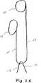
Im Folgenden wird die vorliegende Erfindung beispielhaft unter Bezugnahme auf die beigefügte Zeichnung beschrieben. In der Zeichnung bezeichnen selbe Bezugszeichen gleiche oder identische Bauteile. In der Zeichnung gilt:In the following, the present invention will be described by way of example with reference to the accompanying drawings. In the drawing, same reference numerals designate the same or identical components. In the drawing:
Die Wandung
Der Schaft
Die Schaftöffnungen
Die Schaftöffnungen
Durch die Schaftöffnungen
Die Fäden
Wie im geschnittenen unteren Bereich
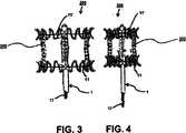
In
In einem unteren Bereich des Schafts
In einem unteren Bereich des Schafts
Aufgrund der gleitenden Verbindung der Bündel
Dieser Effekt der unabhängig von einander betätigbaren Bündel (hier die Bünden
Die Spannung des Zugfadens
Es ist offensichtlich, dass dieses „self-balancing design” nicht auf zwei Bündel, welche überdies auch als einzelne Fäden ausgestaltet sein können, und nicht auf einen weiten Zugfaden – hier den Zugfaden
Spannung oder Zug, welche mittels des Zugfadens
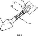
Wie in
Im Teilschnitt ist eine äußere Schutzhülle
Das Implantat
Die Hülse
Die beiden Vertiefungen
Der Steg
Wie in
In der ersten Stellung können (in
Diese erste Stellung eignet sich zum Einführen der Fäden in die Vorrichtung
Zu erkennen ist ferner eine Dichtung
Eine zweite Schaftöffnung
In der zweiten Stellung ist die Vorspanneinrichtung
In der zweiten Stellung sind zwei Fäden (in
In der dritten Stellung ist die Schaftteilöffnung
Wird die Hülse
Diese Stellung, welche aus der dritten Stellung hervor geht, ist in
In
Claims (20)
Translated fromGermanPriority Applications (7)
| Application Number | Priority Date | Filing Date | Title |
|---|---|---|---|
| DE102009055969ADE102009055969A1 (en) | 2009-11-27 | 2009-11-27 | Device and set for folding or unfolding a medical implant and method |
| JP2012540320AJP5805100B2 (en) | 2009-11-27 | 2010-11-26 | Apparatus, set and method for folding or unfolding a medical implant |
| CA2781728ACA2781728C (en) | 2009-11-27 | 2010-11-26 | Apparatus and set for folding or unfolding a medical implant and method |
| US13/512,324US9433502B2 (en) | 2009-11-27 | 2010-11-26 | Apparatus and set for folding or unfolding a medical implant and method |
| PCT/EP2010/007183WO2011063972A1 (en) | 2009-11-27 | 2010-11-26 | Apparatus and set for folding or unfolding a medical implant and method |
| CN201080062573.7ACN102724937B (en) | 2009-11-27 | 2010-11-26 | For folding or launch apparatus and the device and method of medical implant |
| EP10784990.3AEP2509542B1 (en) | 2009-11-27 | 2010-11-26 | Apparatus and set for folding or unfolding a medical implant |
Applications Claiming Priority (1)
| Application Number | Priority Date | Filing Date | Title |
|---|---|---|---|
| DE102009055969ADE102009055969A1 (en) | 2009-11-27 | 2009-11-27 | Device and set for folding or unfolding a medical implant and method |
Publications (1)
| Publication Number | Publication Date |
|---|---|
| DE102009055969A1true DE102009055969A1 (en) | 2011-06-01 |
Family
ID=43927122
Family Applications (1)
| Application Number | Title | Priority Date | Filing Date |
|---|---|---|---|
| DE102009055969ACeasedDE102009055969A1 (en) | 2009-11-27 | 2009-11-27 | Device and set for folding or unfolding a medical implant and method |
Country Status (7)
| Country | Link |
|---|---|
| US (1) | US9433502B2 (en) |
| EP (1) | EP2509542B1 (en) |
| JP (1) | JP5805100B2 (en) |
| CN (1) | CN102724937B (en) |
| CA (1) | CA2781728C (en) |
| DE (1) | DE102009055969A1 (en) |
| WO (1) | WO2011063972A1 (en) |
Cited By (2)
| Publication number | Priority date | Publication date | Assignee | Title |
|---|---|---|---|---|
| WO2017214098A1 (en)* | 2016-06-06 | 2017-12-14 | Medtronic Vascular Inc. | Transcatheter prosthetic heart valve delivery system with lateral offset control |
| WO2021028286A1 (en)* | 2019-08-14 | 2021-02-18 | Jotec Gmbh | Vascular prosthesis |
Families Citing this family (51)
| Publication number | Priority date | Publication date | Assignee | Title |
|---|---|---|---|---|
| US8579964B2 (en) | 2010-05-05 | 2013-11-12 | Neovasc Inc. | Transcatheter mitral valve prosthesis |
| US9308087B2 (en) | 2011-04-28 | 2016-04-12 | Neovasc Tiara Inc. | Sequentially deployed transcatheter mitral valve prosthesis |
| US9554897B2 (en) | 2011-04-28 | 2017-01-31 | Neovasc Tiara Inc. | Methods and apparatus for engaging a valve prosthesis with tissue |
| DE102012101103B3 (en)* | 2012-02-10 | 2013-07-04 | Jotec Gmbh | Stentgraft with fixation elements and insertion system |
| US9345573B2 (en) | 2012-05-30 | 2016-05-24 | Neovasc Tiara Inc. | Methods and apparatus for loading a prosthesis onto a delivery system |
| US10376360B2 (en) | 2012-07-27 | 2019-08-13 | W. L. Gore & Associates, Inc. | Multi-frame prosthetic valve apparatus and methods |
| US9968443B2 (en) | 2012-12-19 | 2018-05-15 | W. L. Gore & Associates, Inc. | Vertical coaptation zone in a planar portion of prosthetic heart valve leaflet |
| US9737398B2 (en) | 2012-12-19 | 2017-08-22 | W. L. Gore & Associates, Inc. | Prosthetic valves, frames and leaflets and methods thereof |
| CA2896333C (en) | 2012-12-27 | 2021-01-12 | Transcatheter Technologies Gmbh | Apparatus and set for folding or unfolding a medical implant comprising a clamping mechanism |
| US9572665B2 (en) | 2013-04-04 | 2017-02-21 | Neovasc Tiara Inc. | Methods and apparatus for delivering a prosthetic valve to a beating heart |
| WO2014179763A1 (en) | 2013-05-03 | 2014-11-06 | Medtronic Inc. | Valve delivery tool |
| EP2803335B1 (en)* | 2013-05-14 | 2017-09-27 | Venus MedTech (HangZhou), Inc. | Apparatus for folding or unfolding a medical implant, and implant |
| DE102013106463A1 (en)* | 2013-06-20 | 2014-12-24 | Jotec Gmbh | stent graft |
| EP2918245B1 (en) | 2014-03-14 | 2017-05-03 | Venus MedTech (HangZhou), Inc. | Heart valve comprising a crown piece interconnected to leaflets, a top cuff and a bottom cuff; and a medical implant |
| EP2832315B1 (en)* | 2013-07-31 | 2017-11-22 | Venus MedTech (HangZhou), Inc. | Handle assembly for implant delivery apparatus comprising a brake frame assembly, a force limiter and/or a displacement limiter |
| EP2832317B1 (en) | 2013-07-31 | 2017-02-15 | Venus MedTech (HangZhou), Inc. | Implant delivery device for folding or unfolding a medical implant based on a knot |
| US10149758B2 (en) | 2014-04-01 | 2018-12-11 | Medtronic, Inc. | System and method of stepped deployment of prosthetic heart valve |
| EP3294220B1 (en)* | 2015-05-14 | 2023-12-06 | Cephea Valve Technologies, Inc. | Cardiac valve delivery devices and systems |
| CN108472136B (en) | 2015-12-14 | 2020-11-24 | 美敦力瓦斯科尔勒公司 | Devices and methods for transcatheter valve loading and implantation |
| CA3007660A1 (en) | 2015-12-15 | 2017-06-22 | Neovasc Tiara Inc. | Transseptal delivery system |
| US10433952B2 (en) | 2016-01-29 | 2019-10-08 | Neovasc Tiara Inc. | Prosthetic valve for avoiding obstruction of outflow |
| US10893938B2 (en) | 2016-03-03 | 2021-01-19 | Medtronic Vascular, Inc. | Stented prosthesis delivery system having a bumper |
| US10420642B2 (en) | 2016-03-14 | 2019-09-24 | Medtronic Vascular, Inc. | Transcatheter stented prosthetic heart valve delivery devices |
| CN108834399B (en) | 2016-03-14 | 2024-06-11 | 美敦力瓦斯科尔勒公司 | Stented prosthetic heart valve with wrap and delivery device |
| CA3042588A1 (en) | 2016-11-21 | 2018-05-24 | Neovasc Tiara Inc. | Methods and systems for rapid retraction of a transcatheter heart valve delivery system |
| US10433993B2 (en) | 2017-01-20 | 2019-10-08 | Medtronic Vascular, Inc. | Valve prosthesis having a radially-expandable sleeve integrated thereon for delivery and prevention of paravalvular leakage |
| US10561497B2 (en) | 2017-03-07 | 2020-02-18 | Medtronic Vascular, Inc. | Delivery system having a short capsule segment and a cinch mechanism and methods of use thereof |
| EP3592292B1 (en) | 2017-03-09 | 2024-11-06 | Medtronic Inc. | Stented prosthesis delivery devices having steering capabilities |
| US10856980B2 (en) | 2017-05-08 | 2020-12-08 | Medtronic Vascular, Inc. | Prosthetic valve delivery system and method |
| CA3073834A1 (en) | 2017-08-25 | 2019-02-28 | Neovasc Tiara Inc. | Sequentially deployed transcatheter mitral valve prosthesis |
| WO2019055577A1 (en) | 2017-09-12 | 2019-03-21 | W. L. Gore & Associates, Inc. | Leaflet frame attachment for prosthetic valves |
| CN111132636B (en) | 2017-09-27 | 2022-04-08 | W.L.戈尔及同仁股份有限公司 | Prosthetic valve with expandable frame and related systems and methods |
| CN111163728B (en) | 2017-09-27 | 2022-04-29 | W.L.戈尔及同仁股份有限公司 | Prosthetic valve with mechanically coupled leaflets |
| US11090153B2 (en) | 2017-10-13 | 2021-08-17 | W. L. Gore & Associates, Inc. | Telescoping prosthetic valve and delivery system |
| JP7072062B2 (en)* | 2017-10-31 | 2022-05-19 | ダブリュ.エル.ゴア アンド アソシエイツ,インコーポレイティド | Transcatheter placement system and related methods |
| CN111295158A (en) | 2017-10-31 | 2020-06-16 | W.L.戈尔及同仁股份有限公司 | Medical valve and valve leaflet for promoting tissue ingrowth |
| AU2019325548B2 (en) | 2018-08-21 | 2025-06-26 | Shifamed Holdings, Llc | Prosthetic cardiac valve devices, systems, and methods |
| CN113260337A (en) | 2018-10-05 | 2021-08-13 | 施菲姆德控股有限责任公司 | Prosthetic heart valve devices, systems, and methods |
| CN113056302B (en) | 2018-10-19 | 2023-03-28 | 施菲姆德控股有限责任公司 | Adjustable medical device |
| CN113271890B (en) | 2018-11-08 | 2024-08-30 | 内奥瓦斯克迪亚拉公司 | Ventricular deployment of transcatheter mitral valve prosthesis |
| US11497601B2 (en) | 2019-03-01 | 2022-11-15 | W. L. Gore & Associates, Inc. | Telescoping prosthetic valve with retention element |
| CA3132873A1 (en) | 2019-03-08 | 2020-09-17 | Neovasc Tiara Inc. | Retrievable prosthesis delivery system |
| CA3135753C (en) | 2019-04-01 | 2023-10-24 | Neovasc Tiara Inc. | Controllably deployable prosthetic valve |
| US11491006B2 (en) | 2019-04-10 | 2022-11-08 | Neovasc Tiara Inc. | Prosthetic valve with natural blood flow |
| US11779742B2 (en) | 2019-05-20 | 2023-10-10 | Neovasc Tiara Inc. | Introducer with hemostasis mechanism |
| JP7520897B2 (en) | 2019-06-20 | 2024-07-23 | ニオバスク ティアラ インコーポレイテッド | Thin prosthetic mitral valve |
| US11801131B2 (en) | 2019-12-20 | 2023-10-31 | Medtronic Vascular, Inc. | Elliptical heart valve prostheses, delivery systems, and methods of use |
| EP4114313B1 (en)* | 2020-03-03 | 2025-10-01 | Shifamed Holdings, LLC | Prosthetic cardiac valve devices, systems |
| US12329635B2 (en) | 2020-12-04 | 2025-06-17 | Shifamed Holdings, Llc | Flared prosthetic cardiac valve delivery devices and systems |
| US12201521B2 (en) | 2021-03-22 | 2025-01-21 | Shifamed Holdings, Llc | Anchor position verification for prosthetic cardiac valve devices |
| WO2024092162A2 (en)* | 2022-10-26 | 2024-05-02 | Shifamed Holdings, Llc | Prosthetic heart valve delivery system and method |
Citations (3)
| Publication number | Priority date | Publication date | Assignee | Title |
|---|---|---|---|---|
| US20050119722A1 (en)* | 2003-09-12 | 2005-06-02 | Mikolaj Styrc | Device for treating a blood vessel and a method of preparing the device |
| US20090005863A1 (en)* | 2006-02-16 | 2009-01-01 | Goetz Wolfgang | Minimally invasive heart valve replacement |
| US20090099640A1 (en)* | 2006-03-30 | 2009-04-16 | Ning Weng | Axial Pullwire Tension Mechanism for Self-Expanding Stent |
Family Cites Families (44)
| Publication number | Priority date | Publication date | Assignee | Title |
|---|---|---|---|---|
| CA2081424C (en)* | 1991-10-25 | 2008-12-30 | Timothy A. Chuter | Expandable transluminal graft prosthesis for repair of aneurysm |
| US5693084A (en)* | 1991-10-25 | 1997-12-02 | Cook Incorporated | Expandable transluminal graft prosthesis for repair of aneurysm |
| US5387235A (en)* | 1991-10-25 | 1995-02-07 | Cook Incorporated | Expandable transluminal graft prosthesis for repair of aneurysm |
| JP3324707B2 (en)* | 1992-04-15 | 2002-09-17 | クック インコーポレイティド | Device for placing a prosthesis in a patient's organ and device for organ transplantation |
| US5405378A (en)* | 1992-05-20 | 1995-04-11 | Strecker; Ernst P. | Device with a prosthesis implantable in the body of a patient |
| US5336178A (en)* | 1992-11-02 | 1994-08-09 | Localmed, Inc. | Intravascular catheter with infusion array |
| US5480423A (en)* | 1993-05-20 | 1996-01-02 | Boston Scientific Corporation | Prosthesis delivery |
| US5800521A (en)* | 1994-11-09 | 1998-09-01 | Endotex Interventional Systems, Inc. | Prosthetic graft and method for aneurysm repair |
| WO1996036297A1 (en)* | 1995-05-19 | 1996-11-21 | Kanji Inoue | Transplantation instrument, method of bending same and method of transplanting same |
| US6287315B1 (en)* | 1995-10-30 | 2001-09-11 | World Medical Manufacturing Corporation | Apparatus for delivering an endoluminal prosthesis |
| US6626914B2 (en)* | 1996-05-17 | 2003-09-30 | Jomed N.V. | Graft connector, an introducer therefor and a method of making a branch connection |
| SE514595C2 (en)* | 1999-08-25 | 2001-03-19 | Jan Otto Solem | Transplant coupling and insertion device for this |
| US5941908A (en)* | 1997-04-23 | 1999-08-24 | Vascular Science, Inc. | Artificial medical graft with a releasable retainer |
| US5957949A (en)* | 1997-05-01 | 1999-09-28 | World Medical Manufacturing Corp. | Percutaneous placement valve stent |
| US6599311B1 (en) | 1998-06-05 | 2003-07-29 | Broncus Technologies, Inc. | Method and assembly for lung volume reduction |
| WO2000002615A1 (en)* | 1998-07-10 | 2000-01-20 | Shin Ishimaru | Stent (or stent graft) indwelling device |
| JP2000325484A (en)* | 1999-05-24 | 2000-11-28 | Terumo Corp | Apparatus for medical treatment of lesion in celom |
| US6398802B1 (en)* | 1999-06-21 | 2002-06-04 | Scimed Life Systems, Inc. | Low profile delivery system for stent and graft deployment |
| WO2002015795A2 (en)* | 2000-08-25 | 2002-02-28 | Sutura, Inc. | Suture cutter |
| US6899727B2 (en)* | 2001-01-22 | 2005-05-31 | Gore Enterprise Holdings, Inc. | Deployment system for intraluminal devices |
| SE0101887L (en)* | 2001-05-30 | 2002-12-01 | Jan Otto Solem | Vascular instrument and method |
| US7147657B2 (en)* | 2003-10-23 | 2006-12-12 | Aptus Endosystems, Inc. | Prosthesis delivery systems and methods |
| WO2003079935A1 (en)* | 2002-03-18 | 2003-10-02 | Eva Corporation | Method and apparatus to attach an unsupported surgical component |
| US20030225445A1 (en)* | 2002-05-14 | 2003-12-04 | Derus Patricia M. | Surgical stent delivery devices and methods |
| DE60302459T2 (en)* | 2002-05-29 | 2006-08-03 | Cook Inc., Bloomington | TRIGGER WIRE SYSTEM FOR A PROSTHESIS PLASMA DEVICE |
| US20040015224A1 (en)* | 2002-07-22 | 2004-01-22 | Armstrong Joseph R. | Endoluminal expansion system |
| US7611528B2 (en)* | 2003-01-24 | 2009-11-03 | Medtronic Vascular, Inc. | Stent-graft delivery system |
| US7381210B2 (en)* | 2003-03-14 | 2008-06-03 | Edwards Lifesciences Corporation | Mitral valve repair system and method for use |
| US7192440B2 (en)* | 2003-10-15 | 2007-03-20 | Xtent, Inc. | Implantable stent delivery devices and methods |
| WO2005037361A2 (en)* | 2003-10-22 | 2005-04-28 | Colin Charles Didcott | Dilators and dilator assemblies |
| US8057533B2 (en)* | 2003-10-29 | 2011-11-15 | Boston Scientific Scimed, Inc. | Apparatus with visual marker for guiding deployment of implantable prosthesis |
| DE102004012351A1 (en)* | 2004-03-11 | 2005-09-29 | pfm Produkte für die Medizin AG | Device for recanalizing a cavity, organ or vessel |
| DE602005024585D1 (en)* | 2004-09-28 | 2010-12-16 | Cook William Europ | DEVICE FOR TREATING AORTIAL DISEASE |
| US8252005B2 (en)* | 2005-06-30 | 2012-08-28 | Edwards Lifesciences Corporation | System, apparatus, and method for fastening tissue |
| US7909863B2 (en)* | 2006-02-27 | 2011-03-22 | Cook Incorporated | Retention of exposed stent loops |
| US9510962B2 (en)* | 2006-06-16 | 2016-12-06 | Olympus Corporation | Stent delivery system |
| WO2008066923A1 (en)* | 2006-11-30 | 2008-06-05 | William Cook Europe Aps | Implant release mechanism |
| US8187284B2 (en)* | 2007-04-23 | 2012-05-29 | Boston Scientific Scimed, Inc. | Intraluminary stent relocating apparatus |
| US9119742B2 (en)* | 2007-07-16 | 2015-09-01 | Cook Medical Technologies Llc | Prosthesis delivery and deployment device |
| US8915951B2 (en)* | 2008-02-11 | 2014-12-23 | Boston Scientific Scimed, Inc. | Self-expandable stent with a constrictive coating and method of use |
| DE102008012113A1 (en) | 2008-03-02 | 2009-09-03 | Transcatheter Technologies Gmbh | Implant e.g. heart-valve-carrying stent, for e.g. arresting blood vessel, has fiber by which section of implant is reducible according to increasing of implant at extended diameter by unfolding or expansion of diameter with expansion unit |
| CN101283937B (en)* | 2008-05-21 | 2010-08-18 | 微创医疗器械(上海)有限公司 | Overlay film frame with an opening and bonding method of the overlay film frame |
| US8034094B2 (en)* | 2008-06-11 | 2011-10-11 | Olympus Medical Systems Corp. | Stent delivery system and stent delivery method |
| US8523932B2 (en)* | 2010-05-24 | 2013-09-03 | Cook Medical Technologies Llc | Variable diameter trigger wire |
- 2009
- 2009-11-27DEDE102009055969Apatent/DE102009055969A1/ennot_activeCeased
- 2010
- 2010-11-26JPJP2012540320Apatent/JP5805100B2/enactiveActive
- 2010-11-26WOPCT/EP2010/007183patent/WO2011063972A1/enactiveApplication Filing
- 2010-11-26CACA2781728Apatent/CA2781728C/enactiveActive
- 2010-11-26CNCN201080062573.7Apatent/CN102724937B/enactiveActive
- 2010-11-26USUS13/512,324patent/US9433502B2/enactiveActive
- 2010-11-26EPEP10784990.3Apatent/EP2509542B1/enactiveActive
Patent Citations (3)
| Publication number | Priority date | Publication date | Assignee | Title |
|---|---|---|---|---|
| US20050119722A1 (en)* | 2003-09-12 | 2005-06-02 | Mikolaj Styrc | Device for treating a blood vessel and a method of preparing the device |
| US20090005863A1 (en)* | 2006-02-16 | 2009-01-01 | Goetz Wolfgang | Minimally invasive heart valve replacement |
| US20090099640A1 (en)* | 2006-03-30 | 2009-04-16 | Ning Weng | Axial Pullwire Tension Mechanism for Self-Expanding Stent |
Cited By (5)
| Publication number | Priority date | Publication date | Assignee | Title |
|---|---|---|---|---|
| WO2017214098A1 (en)* | 2016-06-06 | 2017-12-14 | Medtronic Vascular Inc. | Transcatheter prosthetic heart valve delivery system with lateral offset control |
| AU2017278331B2 (en)* | 2016-06-06 | 2020-01-30 | Medtronic Vascular Inc. | Transcatheter prosthetic heart valve delivery system with lateral offset control |
| US10765513B2 (en) | 2016-06-06 | 2020-09-08 | Medtronic Vascular, Inc. | Transcatheter prosthetic heart valve delivery system with lateral offset control |
| US11903828B2 (en) | 2016-06-06 | 2024-02-20 | Medtronic Vascular, Inc. | Transcatheter prosthetic heart valve delivery system with lateral offset control |
| WO2021028286A1 (en)* | 2019-08-14 | 2021-02-18 | Jotec Gmbh | Vascular prosthesis |
Also Published As
| Publication number | Publication date |
|---|---|
| US20120277734A1 (en) | 2012-11-01 |
| WO2011063972A8 (en) | 2011-07-14 |
| EP2509542B1 (en) | 2019-07-10 |
| US9433502B2 (en) | 2016-09-06 |
| CA2781728A1 (en) | 2011-06-03 |
| JP2013512013A (en) | 2013-04-11 |
| EP2509542A1 (en) | 2012-10-17 |
| CA2781728C (en) | 2018-06-12 |
| CN102724937A (en) | 2012-10-10 |
| JP5805100B2 (en) | 2015-11-04 |
| CN102724937B (en) | 2015-08-12 |
| WO2011063972A1 (en) | 2011-06-03 |
Similar Documents
| Publication | Publication Date | Title |
|---|---|---|
| DE102009055969A1 (en) | Device and set for folding or unfolding a medical implant and method | |
| DE102010061371A1 (en) | Individual shaft fiber device and kit for folding or deploying a medical implant and method | |
| DE102008014730B4 (en) | Device for expanding a radially expandable implant, device set and method for expanding the implant and placement tool | |
| DE202009001951U1 (en) | Medical instrument | |
| DE102015111205A1 (en) | Treatment device of a bloodstream | |
| DE3643362A1 (en) | PROBE FOR INTRODUCTION IN HUMAN OR ANIMAL BODIES, IN PARTICULAR PAPILLOTOM | |
| DE112013001718T5 (en) | Medical devices and systems for manipulating foreign bodies and methods for their use | |
| DE102010037529A1 (en) | Device intended to be attached to or attached to a catheter, catheter and method | |
| DE202008007774U1 (en) | endoscope cap | |
| DE112009001316T5 (en) | Apparatus for treating a blood circulation channel | |
| DE102009037047A1 (en) | Tubular shaft of a surgical instrument | |
| DE112015000400T5 (en) | Surgical instrument for the cardiac ear | |
| DE3201702A1 (en) | DEVICE FOR ADJUSTING THE FIT OF THE FOOT IN THE SHOE, IN PARTICULAR FOR SKI SHOES | |
| DE102006047675A1 (en) | Guidewire with core and distal sheath | |
| DE102014208168A1 (en) | Fangkelinstrument with distal Fangkelchstruktur | |
| EP1319372B1 (en) | Device for holding a trocar sleeve | |
| DE102011055236A1 (en) | Surgical instrument | |
| WO2010133215A1 (en) | Application device for applying, particularly for endoscopically applying, a medical clip in or on the body of an individual | |
| EP3320862B1 (en) | Device for positioning and release of a closure implant for closing the left atrial auricle | |
| DE102016001292B4 (en) | Surgical stone catching instrument | |
| DE102005030010B4 (en) | Stone catcher unit | |
| DE112018007936T5 (en) | Endoscope treatment tool | |
| DE10145107B4 (en) | Staff for endoscopes | |
| DE20217525U1 (en) | Method for fitting orthopaedic cover for stump has a double layer sleeve with pull loops at the bottom for easy removal when the cover is fitted | |
| DE112022002218T5 (en) | Device and method for tensioning and fixing valve bands |
Legal Events
| Date | Code | Title | Description |
|---|---|---|---|
| OP8 | Request for examination as to paragraph 44 patent law | ||
| R079 | Amendment of ipc main class | Free format text:PREVIOUS MAIN CLASS: A61F0002840000 Ipc:A61F0002950000 Effective date:20121227 | |
| R082 | Change of representative | Representative=s name:BOBBERT & PARTNER PATENTANWAELTE PARTMBB, DE Representative=s name:ZENZ PATENTANWAELTE PARTNERSCHAFT MBB, DE | |
| R081 | Change of applicant/patentee | Owner name:VENUS MEDTECH (HANGZHOU) LNC., HANGZHOU, CN Free format text:FORMER OWNER: TRANSCATHETER TECHNOLOGIES GMBH, 93053 REGENSBURG, DE | |
| R082 | Change of representative | Representative=s name:BOBBERT & PARTNER PATENTANWAELTE PARTMBB, DE Representative=s name:ZENZ PATENTANWAELTE PARTNERSCHAFT MBB, DE | |
| R082 | Change of representative | Representative=s name:ZENZ PATENTANWAELTE PARTNERSCHAFT MBB, DE | |
| R016 | Response to examination communication | ||
| R016 | Response to examination communication | ||
| R002 | Refusal decision in examination/registration proceedings | ||
| R003 | Refusal decision now final |