DE102009043226A1 - Flat body in the manner of a chip card for biochemical analysis and method for its use - Google Patents
Flat body in the manner of a chip card for biochemical analysis and method for its useDownload PDFInfo
- Publication number
- DE102009043226A1 DE102009043226A1DE102009043226ADE102009043226ADE102009043226A1DE 102009043226 A1DE102009043226 A1DE 102009043226A1DE 102009043226 ADE102009043226 ADE 102009043226ADE 102009043226 ADE102009043226 ADE 102009043226ADE 102009043226 A1DE102009043226 A1DE 102009043226A1
- Authority
- DE
- Germany
- Prior art keywords
- flat body
- cup
- microfluidic device
- sensor chip
- liquid
- Prior art date
- Legal status (The legal status is an assumption and is not a legal conclusion. Google has not performed a legal analysis and makes no representation as to the accuracy of the status listed.)
- Granted
Links
- 238000012742biochemical analysisMethods0.000titleclaimsabstractdescription10
- 238000002306biochemical methodMethods0.000title1
- 239000007788liquidSubstances0.000claimsabstractdescription65
- 239000000126substanceSubstances0.000claimsabstractdescription35
- 238000000034methodMethods0.000claimsabstractdescription12
- 238000006243chemical reactionMethods0.000claimsdescription16
- 239000004033plasticSubstances0.000claimsdescription9
- 239000000463materialSubstances0.000claimsdescription8
- 239000003153chemical reaction reagentSubstances0.000claimsdescription6
- 239000007795chemical reaction productSubstances0.000claimsdescription5
- 238000012545processingMethods0.000claimsdescription5
- 210000002700urineAnatomy0.000claimsdescription5
- 239000008280bloodSubstances0.000claimsdescription4
- 210000004369bloodAnatomy0.000claimsdescription4
- 239000002991molded plasticSubstances0.000claimsdescription4
- 102000004196processed proteins & peptidesHuman genes0.000claimsdescription3
- 108090000765processed proteins & peptidesProteins0.000claimsdescription3
- -1urineSubstances0.000claimsdescription3
- 239000013505freshwaterSubstances0.000claimsdescription2
- 239000002351wastewaterSubstances0.000claimsdescription2
- 239000002313adhesive filmSubstances0.000claims1
- 238000003032molecular dockingMethods0.000abstract1
- 238000001514detection methodMethods0.000description13
- 239000012530fluidSubstances0.000description8
- 239000011888foilSubstances0.000description6
- 238000004519manufacturing processMethods0.000description5
- 239000000243solutionSubstances0.000description4
- 230000007704transitionEffects0.000description3
- 239000000853adhesiveSubstances0.000description2
- 239000000470constituentSubstances0.000description2
- 230000001419dependent effectEffects0.000description2
- 238000002848electrochemical methodMethods0.000description2
- 239000012535impuritySubstances0.000description2
- 238000002347injectionMethods0.000description2
- 239000007924injectionSubstances0.000description2
- 230000003287optical effectEffects0.000description2
- 238000002360preparation methodMethods0.000description2
- 239000004065semiconductorSubstances0.000description2
- 235000013619trace mineralNutrition0.000description2
- 239000011573trace mineralSubstances0.000description2
- BUHVIAUBTBOHAG-FOYDDCNASA-N(2r,3r,4s,5r)-2-[6-[[2-(3,5-dimethoxyphenyl)-2-(2-methylphenyl)ethyl]amino]purin-9-yl]-5-(hydroxymethyl)oxolane-3,4-diolChemical compoundCOC1=CC(OC)=CC(C(CNC=2C=3N=CN(C=3N=CN=2)[C@H]2[C@@H]([C@H](O)[C@@H](CO)O2)O)C=2C(=CC=CC=2)C)=C1BUHVIAUBTBOHAG-FOYDDCNASA-N0.000description1
- 238000010521absorption reactionMethods0.000description1
- 238000004026adhesive bondingMethods0.000description1
- 230000003321amplificationEffects0.000description1
- 238000004140cleaningMethods0.000description1
- 230000001427coherent effectEffects0.000description1
- 239000012141concentrateSubstances0.000description1
- 239000000356contaminantSubstances0.000description1
- 238000011109contaminationMethods0.000description1
- 230000009089cytolysisEffects0.000description1
- 238000011161developmentMethods0.000description1
- 230000018109developmental processEffects0.000description1
- 230000029087digestionEffects0.000description1
- 239000003651drinking waterSubstances0.000description1
- 235000020188drinking waterNutrition0.000description1
- 239000007789gasSubstances0.000description1
- 239000008235industrial waterSubstances0.000description1
- 238000001746injection mouldingMethods0.000description1
- 238000011835investigationMethods0.000description1
- 238000002032lab-on-a-chipMethods0.000description1
- 238000002372labellingMethods0.000description1
- 238000005259measurementMethods0.000description1
- 239000002184metalSubstances0.000description1
- 238000003199nucleic acid amplification methodMethods0.000description1
- 102000004169proteins and genesHuman genes0.000description1
- 108090000623proteins and genesProteins0.000description1
- 239000002689soilSubstances0.000description1
- 239000007790solid phaseSubstances0.000description1
- 239000002699waste materialSubstances0.000description1
- XLYOFNOQVPJJNP-UHFFFAOYSA-NwaterSubstancesOXLYOFNOQVPJJNP-UHFFFAOYSA-N0.000description1
Images

Classifications
- B—PERFORMING OPERATIONS; TRANSPORTING
- B01—PHYSICAL OR CHEMICAL PROCESSES OR APPARATUS IN GENERAL
- B01L—CHEMICAL OR PHYSICAL LABORATORY APPARATUS FOR GENERAL USE
- B01L3/00—Containers or dishes for laboratory use, e.g. laboratory glassware; Droppers
- B01L3/50—Containers for the purpose of retaining a material to be analysed, e.g. test tubes
- B01L3/502—Containers for the purpose of retaining a material to be analysed, e.g. test tubes with fluid transport, e.g. in multi-compartment structures
- B01L3/5027—Containers for the purpose of retaining a material to be analysed, e.g. test tubes with fluid transport, e.g. in multi-compartment structures by integrated microfluidic structures, i.e. dimensions of channels and chambers are such that surface tension forces are important, e.g. lab-on-a-chip
- B01L3/502715—Containers for the purpose of retaining a material to be analysed, e.g. test tubes with fluid transport, e.g. in multi-compartment structures by integrated microfluidic structures, i.e. dimensions of channels and chambers are such that surface tension forces are important, e.g. lab-on-a-chip characterised by interfacing components, e.g. fluidic, electrical, optical or mechanical interfaces
- B—PERFORMING OPERATIONS; TRANSPORTING
- B01—PHYSICAL OR CHEMICAL PROCESSES OR APPARATUS IN GENERAL
- B01L—CHEMICAL OR PHYSICAL LABORATORY APPARATUS FOR GENERAL USE
- B01L2200/00—Solutions for specific problems relating to chemical or physical laboratory apparatus
- B01L2200/02—Adapting objects or devices to another
- B01L2200/026—Fluid interfacing between devices or objects, e.g. connectors, inlet details
- B01L2200/027—Fluid interfacing between devices or objects, e.g. connectors, inlet details for microfluidic devices
- B—PERFORMING OPERATIONS; TRANSPORTING
- B01—PHYSICAL OR CHEMICAL PROCESSES OR APPARATUS IN GENERAL
- B01L—CHEMICAL OR PHYSICAL LABORATORY APPARATUS FOR GENERAL USE
- B01L2300/00—Additional constructional details
- B01L2300/06—Auxiliary integrated devices, integrated components
- B01L2300/0627—Sensor or part of a sensor is integrated
- B01L2300/0663—Whole sensors
- B—PERFORMING OPERATIONS; TRANSPORTING
- B01—PHYSICAL OR CHEMICAL PROCESSES OR APPARATUS IN GENERAL
- B01L—CHEMICAL OR PHYSICAL LABORATORY APPARATUS FOR GENERAL USE
- B01L2300/00—Additional constructional details
- B01L2300/06—Auxiliary integrated devices, integrated components
- B01L2300/0672—Integrated piercing tool
- B—PERFORMING OPERATIONS; TRANSPORTING
- B01—PHYSICAL OR CHEMICAL PROCESSES OR APPARATUS IN GENERAL
- B01L—CHEMICAL OR PHYSICAL LABORATORY APPARATUS FOR GENERAL USE
- B01L2300/00—Additional constructional details
- B01L2300/08—Geometry, shape and general structure
- B01L2300/0809—Geometry, shape and general structure rectangular shaped
- B01L2300/0816—Cards, e.g. flat sample carriers usually with flow in two horizontal directions
- B—PERFORMING OPERATIONS; TRANSPORTING
- B01—PHYSICAL OR CHEMICAL PROCESSES OR APPARATUS IN GENERAL
- B01L—CHEMICAL OR PHYSICAL LABORATORY APPARATUS FOR GENERAL USE
- B01L2300/00—Additional constructional details
- B01L2300/08—Geometry, shape and general structure
- B01L2300/0861—Configuration of multiple channels and/or chambers in a single devices
- B01L2300/0883—Serpentine channels
- B—PERFORMING OPERATIONS; TRANSPORTING
- B01—PHYSICAL OR CHEMICAL PROCESSES OR APPARATUS IN GENERAL
- B01L—CHEMICAL OR PHYSICAL LABORATORY APPARATUS FOR GENERAL USE
- B01L2300/00—Additional constructional details
- B01L2300/08—Geometry, shape and general structure
- B01L2300/0887—Laminated structure
- B—PERFORMING OPERATIONS; TRANSPORTING
- B01—PHYSICAL OR CHEMICAL PROCESSES OR APPARATUS IN GENERAL
- B01L—CHEMICAL OR PHYSICAL LABORATORY APPARATUS FOR GENERAL USE
- B01L2400/00—Moving or stopping fluids
- B01L2400/04—Moving fluids with specific forces or mechanical means
- B01L2400/0403—Moving fluids with specific forces or mechanical means specific forces
- B01L2400/0406—Moving fluids with specific forces or mechanical means specific forces capillary forces
- B—PERFORMING OPERATIONS; TRANSPORTING
- B01—PHYSICAL OR CHEMICAL PROCESSES OR APPARATUS IN GENERAL
- B01L—CHEMICAL OR PHYSICAL LABORATORY APPARATUS FOR GENERAL USE
- B01L3/00—Containers or dishes for laboratory use, e.g. laboratory glassware; Droppers
- B01L3/02—Burettes; Pipettes
- B01L3/021—Pipettes, i.e. with only one conduit for withdrawing and redistributing liquids
- B—PERFORMING OPERATIONS; TRANSPORTING
- B01—PHYSICAL OR CHEMICAL PROCESSES OR APPARATUS IN GENERAL
- B01L—CHEMICAL OR PHYSICAL LABORATORY APPARATUS FOR GENERAL USE
- B01L3/00—Containers or dishes for laboratory use, e.g. laboratory glassware; Droppers
- B01L3/50—Containers for the purpose of retaining a material to be analysed, e.g. test tubes
- B01L3/508—Containers for the purpose of retaining a material to be analysed, e.g. test tubes rigid containers not provided for above
- B01L3/5082—Test tubes per se
- Y—GENERAL TAGGING OF NEW TECHNOLOGICAL DEVELOPMENTS; GENERAL TAGGING OF CROSS-SECTIONAL TECHNOLOGIES SPANNING OVER SEVERAL SECTIONS OF THE IPC; TECHNICAL SUBJECTS COVERED BY FORMER USPC CROSS-REFERENCE ART COLLECTIONS [XRACs] AND DIGESTS
- Y10—TECHNICAL SUBJECTS COVERED BY FORMER USPC
- Y10T—TECHNICAL SUBJECTS COVERED BY FORMER US CLASSIFICATION
- Y10T436/00—Chemistry: analytical and immunological testing
- Y10T436/14—Heterocyclic carbon compound [i.e., O, S, N, Se, Te, as only ring hetero atom]
- Y10T436/142222—Hetero-O [e.g., ascorbic acid, etc.]
- Y10T436/143333—Saccharide [e.g., DNA, etc.]
Landscapes
- Chemical & Material Sciences (AREA)
- Health & Medical Sciences (AREA)
- Dispersion Chemistry (AREA)
- Analytical Chemistry (AREA)
- General Health & Medical Sciences (AREA)
- Hematology (AREA)
- Clinical Laboratory Science (AREA)
- Chemical Kinetics & Catalysis (AREA)
- Automatic Analysis And Handling Materials Therefor (AREA)
- Investigating Or Analysing Biological Materials (AREA)
- Physical Or Chemical Processes And Apparatus (AREA)
- Apparatus Associated With Microorganisms And Enzymes (AREA)
Abstract
Translated fromGermanDescription
Translated fromGermanDie vorliegende Erfindung umfasst einen Flachkörper nach Art einer Chip-Karte zur biochemischen Analyse von Substanzen sowie ein Verfahren zu dessen Verwendung. Der Flachkörper weist wenigstens zwei mikrofluidische Einrichtungen und wenigstens einen Sensor-Chip auf. Der wenigstens eine Sensor-Chip ist in dem Flachkörper integriert und steht in direktem Kontakt mit wenigstens einer ersten mikrofluidischen Einrichtung.The present invention comprises a flat body in the manner of a chip card for the biochemical analysis of substances and a method for its use. The flat body has at least two microfluidic devices and at least one sensor chip. The at least one sensor chip is integrated in the flat body and is in direct contact with at least one first microfluidic device.
In der Biosensorik werden Lab-on-a Chip Systeme eingesetzt, um einfach und kostensparend biochemische Analysen durchführen zu können. So ist z. B. aus der
Bei einer biochemischen Analyse einer Flüssigkeit, wie sie z. B. durch Blut oder Urin gegeben ist, wird über eine spitze Nadel analog einer Spritzenspitze die Folie der Chip-Karte durchstochen, und die Flüssigkeit wird in eine mikrofluidische Einrichtung der Chip-Karte injiziert. Über Kanäle und Reaktionskammern gelangt die Flüssigkeit in Kontakt mit Sensoren des Sensor-Arrays auf dem Chip und Bestandteile der Flüssigkeit können direkt oder indirekt nachgewiesen werden. Ein Nachweis kann optisch oder elektrochemisch erfolgen. Substanzen, welche für chemische Reaktionen zum Nachweis der Bestandteile der Flüssigkeit notwendig sind, können sich schon auf bzw. in der Chip-Karte befinden oder können ebenfalls in diese über eine spitze Nadel injiziert werden.In a biochemical analysis of a liquid as z. B. is given by blood or urine, the film of the chip card is pierced via a pointed needle analogous to a syringe tip, and the liquid is injected into a microfluidic device of the chip card. Via channels and reaction chambers, the liquid comes into contact with sensors of the sensor array on the chip and constituents of the liquid can be detected directly or indirectly. Detection may be optical or electrochemical. Substances which are necessary for chemical reactions to detect the constituents of the liquid can already be located on or in the chip card or can likewise be injected into this via a pointed needle.
Die Aufnahmekapazität von mikrofluidischen Einrichtungen auf einer Chip-Karte zur Aufnahme von Flüssigkeit ist in der Regel nur sehr gering und ist häufig auf nur wenige Milliliter, oder auf Mikroliter oder im Extremfall nur auf Nanoliter beschränkt. Bei biochemischen Substanzen, welche in der zu untersuchenden Flüssigkeit nur in sehr geringer Konzentration vorkommen, kann dies dazu führen, dass die Gesamtmenge an Flüssigkeit, mit welcher die Chip-Karte befüllt werden kann, nicht ausreicht um die Nachweisgrenze der biochemischen Substanz zu erreichen bzw. zu überschreiten. Ein Nachweis der biochemischen Substanz ist dann nur bei chemischer Vervielfältigung der biochemischen Substanz, z. B. im Fall von DNA durch PCR, möglich. Im Falle des Nachweises ganzer Zellen kann eine zeit- und kostenintensive Vervielfältigung, z. B. in einem Brutschrank notwendig werden. Bei z. B. chemischen Spurenelementen in Urin oder Wasser kann eine chemische Vervielfältigung ausgeschlossen sein und somit ein Nachweis schwer oder gar nicht möglich werden.The absorption capacity of microfluidic devices on a chip card for receiving liquid is usually very low and is often limited to only a few milliliters, or to microliters or in extreme cases only to nanoliters. With biochemical substances, which occur in the liquid to be examined only in very low concentration, this can mean that the total amount of liquid with which the chip card can be filled is insufficient to reach the detection limit of the biochemical substance or To exceed. A proof of the biochemical substance is then only in chemical amplification of the biochemical substance, eg. In the case of DNA by PCR. In the case of the detection of whole cells, a time- and cost-intensive duplication, z. B. be necessary in an incubator. At z. As chemical trace elements in urine or water, a chemical duplication can be excluded and thus a detection difficult or impossible.
Ein weiteres Problem der Zuführung von Flüssigkeit zur bzw. in die Chip-Karte über spitze Nadeln kann in der Einschleppung von Verunreinigungen liegen. Gerade in Hinblick auf einen Nachweis von Spurenelementen, DNA oder Peptiden können geringste chemische oder biochemische Verunreinigungen zu Fehlern beim quantitativen und/oder qualitativen Nachweis führen. Mit jeder zusätzlichen Vorrichtung, wie sie z. B. eine Nadel darstellt, mit welcher die zu untersuchende Flüssigkeit in Kontakt gebracht wird, steigt die Wahrscheinlichkeit der Verunreinigung. Ein erhöhter Aufwand, welcher kosten- und zeitintensiv ist, muss zur Gewährleistung der Nachweisqualität erbracht werden, z. B. durch gründliche Reinigung aller Vorrichtungen.Another problem with supplying liquid to or into the chip card via pointed needles may be the introduction of contaminants. Especially with regard to the detection of trace elements, DNA or peptides, the slightest chemical or biochemical impurities can lead to errors in the quantitative and / or qualitative detection. With each additional device, as z. B. represents a needle with which the liquid to be examined is brought into contact, the probability of contamination increases. An increased effort, which is costly and time-consuming, must be provided to ensure the detection quality, z. B. by thorough cleaning of all devices.
Aufgabe der vorliegenden Erfindung ist es deshalb, einen Flachkörper nach Art einer Chip-Karte zur biochemischen Analyse und insbesondere ein Verfahren zu dessen Verwendung anzugeben, bei welchem es auf einfache und kostengünstige Weise möglich wird Fluide wie z. B. Flüssigkeiten, direkt aus einem Gefäß in mikrofluidische Einrichtungen des Flachkörpers einzubringen. Insbesondere ist es Aufgabe Fluide in die mikrofluidischen Einrichtungen des Flachkörpers einzubringen, wobei die Fluide mit so wenig wie möglich autarken Einzelteilen in Kontakt gebracht werden bzw. diese durchströmen. Weiterhin ist es Aufgabe einen Flachkörper anzugeben, welchem große Mengen an Fluid direkt aus bzw. in ein Gefäß, wie es z. B. ein E-Cup darstellt, zu und/oder abgeführt werden kann.Object of the present invention is therefore to provide a flat body in the manner of a chip card for biochemical analysis and in particular a method for its use, in which it is possible in a simple and cost-effective manner fluids such. As liquids to introduce directly from a vessel in microfluidic devices of the flat body. In particular, it is an object to introduce fluids into the microfluidic devices of the flat body, wherein the fluids are brought into contact with or flow through as few autarkic individual parts as possible. Furthermore, it is an object to provide a flat body, which large amounts of fluid directly from or into a vessel, such as. B. represents an e-cup, to and / or can be removed.
Die angegebene Aufgabe wird bezüglich des Flachkörpers nach Art einer Chip-Karte zur biochemischen Analyse von Substanzen mit den Merkmalen des Anspruchs 1 und bezüglich des Verfahrens zur Verwendung des Flachkörpers mit den Merkmalen des Anspruchs 13 gelöst.The specified object is achieved with respect to the flat body in the manner of a chip card for biochemical analysis of substances having the features of claim 1 and with respect to the method of using the flat body with the features of
Vorteilhafte Ausgestaltungen des erfindungsgemäßen Flachkörpers nach Art einer Chip-Karte zur biochemischen Analyse von Substanzen und des Verfahrens zur Verwendung des Flachkörpers gehen aus den jeweils zugeordneten abhängigen Unteransprüchen hervor. Dabei können die Merkmale des Hauptanspruchs mit Merkmalen der Unteransprüche und Merkmale der Unteransprüche untereinander kombiniert werden.Advantageous embodiments of the flat body according to the invention in the manner of a chip card for the biochemical analysis of substances and of the method for using the flat body will become apparent from the respectively associated dependent subclaims. The features of the main claim with features of Subclaims and features of the claims are combined with each other.
Der erfindungsgemäße Flachkörper nach Art einer Chip-Karte zur biochemischen Analyse von Substanzen umfasst wenigstens zwei mikrofluidische Einrichtungen und wenigstens einen Sensor-Chip. Der wenigstens eine Sensor-Chip ist in dem Flachkörper integriert und steht in direktem Kontakt mit wenigstens einer ersten mikrofluidischen Einrichtung. Der Flachkörper umfasst integral eine zweite mikrofluidische Einrichtung nach Art einer Pipette. Dabei bedeutet Integral, dass die zweite mikrofluidische Einrichtung und der restliche Flachkörper aus wenigstens einem Material gemeinsam hergestellt sind und einen zusammenhängenden Körper bilden, ohne das die zweite mikrofluidische Einrichtung an den Flachkörper gesteckt, geklemmt oder sonstig wiederholt trenn- und befestigbar angebracht ist.The flat body according to the invention in the manner of a chip card for the biochemical analysis of substances comprises at least two microfluidic devices and at least one sensor chip. The at least one sensor chip is integrated in the flat body and is in direct contact with at least one first microfluidic device. The flat body integrally comprises a second microfluidic device in the manner of a pipette. Integral means that the second microfluidic device and the remaining flat body are made of at least one material together and form a coherent body, without the second microfluidic device is attached to the flat body, clamped or otherwise repeatedly attached separable and fastened.
Der Vorteil eines Flachkörpers mit integrierter Pipette liegt in der Möglichkeit große Flüssigkeitsmengen zwischen einem Gefäß, wie es z. B. ein E-Cup darstellt, und dem Flachkörper einfach und schnell auszutauschen. Da der Flachkörper und die darin integrierte Pipette aus einem Material zusammen hergestellt werden können, weisen beide gleiche chemische und biochemische Reinheitsgrade auf. Ein Einschleppen von Verunreinigungen durch zusätzliche Teile in den Flachkörper wird so verhindert. Die mögliche Herstellung in einem Schritt verringert Kosten und Aufwand und führt zu einer höheren Stabilität als bei Aufstecklösungen von z. B. Spritzen-Kanülen-Nadeln aus Metall.The advantage of a flat body with integrated pipette lies in the possibility of large amounts of liquid between a vessel, as z. B. represents an e-cup, and the flat body easy and fast exchange. Since the flat body and the pipette integrated therein can be made of one material together, both have the same chemical and biochemical purity levels. An entrainment of impurities by additional parts in the flat body is thus prevented. The possible production in one step reduces costs and effort and leads to a higher stability than in Aufstecklösungen of z. B. syringe cannula needles made of metal.
Der Flachkörper kann eine erste Klemmeinrichtung umfassen, welche ausgebildet ist eine E-Cup direkt mechanisch an dem Flachkörper zu befestigen. E-Cups werden als Reaktionsgefäße benutzt und sind z. B. von Eppendorf® erhältlich und dann unter der Kurzform „Eppi” bekannt. Die Gefäße weisen standardmäßig verschiedene Größen auf und können entsprechend verschiedene Volumina Lösung, z. B. von 0,2 ml bis 2 ml aufnehmen. Sie zeichnen sich durch eine gute Chemikalienresistenz aus und sind bis über 100°C Formstabil. Die Klemmeinrichtung würde einen Durchmesser im Wesentlichen gleich dem Innendurchmesser einer zu befestigenden E-Cup an ihrer Öffnung aufweisen. Eine mechanische Befestigung der E-Cup direkt an dem Flachkörper durch das Klemmen stellt eine besonders einfache und stabile Möglichkeit dar, die E-Cup an dem Flachkörper zu befestigen.The flat body may comprise a first clamping device, which is designed to attach an e-cup directly mechanically to the flat body. E-cups are used as reaction vessels and are z. B. Eppendorf® known available and then under the short form "Eppi". The vessels have different sizes by default and can be correspondingly different volumes of solution, eg. B. from 0.2 ml to 2 ml. They are characterized by good chemical resistance and are dimensionally stable up to over 100 ° C. The clamping device would have a diameter substantially equal to the inner diameter of an e-cup to be fastened at its opening. A mechanical attachment of the e-cup directly to the flat body by the terminals represents a particularly simple and stable way to attach the e-cup to the flat body.
Der Flachkörper kann eine zweite Klemmeinrichtung umfassen, welche ausgebildet ist einen Deckel einer E-Cup direkt mechanisch an dem Flachkörper zu befestigen. Dies erhöht die Stabilität der Befestigung einer E-Cup an dem Flachkörper und führt zu einer Verbesserung des Handlings, da der Deckel nicht beweglich relativ zum Flachkörper beim Befüllen oder der Entnahme von Flüssigkeit aus der E-Cup stört.The flat body may comprise a second clamping device, which is designed to fasten a lid of an e-cup directly mechanically to the flat body. This increases the stability of the attachment of an E-cup to the flat body and leads to an improvement of the handling, since the lid does not disturb movable relative to the flat body during filling or the removal of liquid from the E-Cup.
Die zweite mikrofluidische Einrichtung kann länglich ausgebildet sein und an einem Ende eine Spitze mit einer fluidischen Öffnung umfassen. Sie kann so ausgebildet sein, dass bei Befestigung einer E-Cup an der ersten und/oder zweiten Klemmeinrichtung die Spitze der zweiten mikrofluidische Einrichtung mit der fluidischen Öffnung im Bereich eines unteren Endes der E-Cup angeordnet ist. Dadurch wird eine nahezu vollständige Entnahme von Flüssigkeit aus der E-Cup mit Hilfe der zweiten mikrofluidischen Einrichtung ermöglicht.The second microfluidic device may be elongated and comprise at one end a tip with a fluidic opening. It can be designed so that when mounting an E-cup on the first and / or second clamping device, the tip of the second microfluidic device is arranged with the fluidic opening in the region of a lower end of the E-cup. As a result, an almost complete removal of liquid from the e-cup is made possible with the aid of the second microfluidic device.
Der Flachkörper kann aus einem Plastik-Material bestehen, insbesondere einer Spritzgussplastik. Spritzgussplastik ist leicht zu verarbeiten und ermöglicht eine kostengünstige Herstellung des Flachkörpers. Die mikrofluidischen Einrichtungen können auf einer Vorderseite des Flachkörpers ausgebildet sein und mit einer Folie, insbesondere einer selbstklebenden Folie aus Plastik-Material, abgedeckt sein. Dies ermöglicht eine einfache und kostengünstige Herstellung des Flachkörpers mit mikrofluidischen Einrichtungen.The flat body may consist of a plastic material, in particular an injection-molded plastic. Injection molding plastic is easy to work with and enables cost-effective production of the flat body. The microfluidic devices may be formed on a front side of the flat body and covered with a foil, in particular a self-adhesive foil of plastic material. This allows a simple and cost-effective production of the flat body with microfluidic devices.
Die wenigstens zwei mikrofluidischen Einrichtungen können Kanäle und/oder Kammern, welche als Vertiefungen in einer flachen Ebene der Vorderseite des Flachkörpers ausgebildet sind, umfassen. Weiterhin können die wenigstens zwei mikrofluidischen Einrichtungen Ventile umfassen, ausgebildet in dem Flachkörper. Die wenigstens zwei mikrofluidischen Einrichtungen können auch eine Ausnehmung umfassen, welche als Vertiefung in einer flachen Ebene der Rückseite des Flachkörpers ausgebildet ist und in welcher der Sensor-Chip eingebettet ist, insbesondere mit elektrischen Kontakten des Sensor-Chips in einer Ebene mit der flachen Ebene der Rückseite des Flachkörpers sowie mit einem Sensor-Array des Sensor-Chips in direktem Kontakt zu wenigstens einer Kammer auf der Vorderseite des Flachkörpers. Die wenigstens zwei mikrofluidischen Einrichtungen sind dadurch geeignet ein gutes Handling von Flüssigkeiten zu ermöglichen und Flüssigkeiten aus einer E-Cup zu Sensoren auf dem Chip zu transportieren. Auf dem Weg aus der E-Cup zu den Sensoren können chemische Reaktionen von Flüssigkeiten bzw. Substanzen in den Flüssigkeiten z. B. in Kammern mit Festphasenreagenzien erfolgen.The at least two microfluidic devices may include channels and / or chambers, which are formed as depressions in a flat plane of the front side of the flat body. Furthermore, the at least two microfluidic devices may comprise valves formed in the flat body. The at least two microfluidic devices may also comprise a recess which is formed as a recess in a flat plane of the rear side of the flat body and in which the sensor chip is embedded, in particular with electrical contacts of the sensor chip in a plane with the flat plane Rear side of the flat body and with a sensor array of the sensor chip in direct contact with at least one chamber on the front side of the flat body. The at least two microfluidic devices are thereby suitable for facilitating good handling of liquids and for transporting liquids from an e-cup to sensors on the chip. On the way from the e-cup to the sensors, chemical reactions of liquids or substances in the liquids z. B. done in chambers with solid phase reagents.
Der Flachkörper kann eine Dicke im Bereich von einem Millimeter, eine Länge im Bereich von 85 Millimeter und eine Breite im Bereich von 54 Millimeter aufweisen. Wenigstens eine mikrofluidische Einrichtung kann ausgebildet sein Trockenreagenzien zu beinhalten, insbesondere in Kanälen und/oder Reaktionsräumen mit einem Querschnitt im Bereich von einem oder mehreren Quadrat-Millimetern. Die zweite mikrofluidische Einrichtung kann eine Länge im Bereich von 45 Millimetern aufweisen.The flat body may have a thickness in the range of one millimeter, a length in the range of 85 millimeters and a width in the range of 54 millimeters. At least one microfluidic device may be configured to include dry reagents, particularly in channels and / or reaction spaces having a cross-section in the range of one or more square millimeters. The second microfluidic device may have a length in the range of 45 millimeters.
Die zweite mikrofluidische Einrichtung kann über die erste mikrofluidische Einrichtung in fluidischen Kontakt mit Sensoren des Sensor-Chips stehen.The second microfluidic device may be in fluidic contact with sensors of the sensor chip via the first microfluidic device.
Ein Querschnitt durch die zweite mikrofluidische Einrichtung, senkrecht zur Vorderseite des Flachkörpers, kann einen im Wesentlichen rechteckigen Außenumfang mit einer offenen Ausnehmung zur Vorderseite des Flachkörpers hin aufweisen. Dadurch wird eine erhöhte Stabilität bei einfacher Herstellung erreicht, da die zweite mikrofluidische Einrichtung die Flache Form des Flachkörpers aufweist.A cross section through the second microfluidic device, perpendicular to the front side of the flat body, may have a substantially rectangular outer periphery with an open recess towards the front side of the flat body. As a result, an increased stability is achieved with a simple production, since the second microfluidic device has the flat shape of the flat body.
Der Sensor-Chip kann ein Array aus elektrochemischen Sensoren umfassen. Dadurch werden mit dem Flachkörper elektrochemische Messungen möglich, welche einfacher, kostengünstiger und besser auf kleinsten Raum durchzuführen sind als optische Messungen. Der Sensor-Chip kann weiterhin eine integrierte Schaltung zum verarbeiten elektrischer Signale der Sensoren umfassen. Der Sensor-Chip kann auch elektrische Kontakte zum elektrischen Auslesen des Sensor-Chips umfassen, insbesondere zum elektrischen Auslesen des Sensor-Chips mit Hilfe einer externen Datenverarbeitungseinheit.The sensor chip may comprise an array of electrochemical sensors. As a result, with the flat body electrochemical measurements are possible, which are easier, cheaper and better to perform in the smallest space than optical measurements. The sensor chip may further comprise an integrated circuit for processing electrical signals from the sensors. The sensor chip can also comprise electrical contacts for the electrical readout of the sensor chip, in particular for the electrical readout of the sensor chip with the aid of an external data processing unit.
Der Flachkörper kann wenigstens eine Öffnung auf seiner Vorder- und/oder Rückseite aufweisen, welche in fluidischem Kontakt mit der wenigstens einen ersten mikrofluidischen Einrichtung steht, und/oder welche ausgebildet ist eine äußere Pumpe anzuschließen. Über diese Öffnung bzw. Öffnungen können zusätzlich kleine Mengen an zum Nachweis verwendeten Substanzen, insbesondere in flüssiger Form dem Flachkörper zugeführt werden. So sind z. B. Labeling-Stoffe in frischer Form vor einer eigentlichen elektrochemischen Messung der Flüssigkeit aus einer E-Cup in den mikrofluidischen Einrichtungen des Flachkörpers zuführbar und können mit Substanzen der Flüssigkeit reagieren. Auch ein Unterdruck in den mikrofluidischen Einrichtungen kann über die wenigstens eine Öffnung z. B. mit Hilfe einer Pumpe erzeugt werden und dazu dienen, Flüssigkeit aus einer E-Cup anzusaugen in den Flachkörper bzw. dessen mikrofluidischen Einrichtungen hinein.The flat body can have at least one opening on its front and / or rear side, which is in fluidic contact with the at least one first microfluidic device, and / or which is designed to connect an external pump. In addition, small amounts of substances used for the detection, in particular in liquid form, can be supplied to the flat body via this opening or openings. So z. B. labeling substances in fresh form before an actual electrochemical measurement of the liquid from an e-cup in the microfluidic devices of the flat body fed and can react with substances of the liquid. Also, a negative pressure in the microfluidic devices can via the at least one opening z. B. be generated by means of a pump and serve to suck liquid from an e-cup in the flat body or its microfluidic devices inside.
Ein erfindungsgemäßes Verfahren zur Verwendung des zuvor beschriebenen Flachkörpers umfasst die Schritte:
- – eine E-Cup wird mit einer zu untersuchenden Flüssigkeit befällt, und
- – die zweite mikrofluidische Einrichtung wird derart in die E-Cup eingeführt, dass sie in direktem Kontakt zu der zu untersuchenden Flüssigkeit steht, und
- – die Flüssigkeit wird durch die zweite mikrofluidische Einrichtung in die erste mikrofluidische Einrichtung transportiert, insbesondere direkt und insbesondere durch einen Unterdruck und/oder Kapillarkräfte, und
- – die zu untersuchende Flüssigkeit wird über den Sensor-Chip gleitet, und
- – wenigstens ein Sensor des Sensor-Chips interagiert mit wenigstens einer chemischen und/oder biochemischen Substanz der zu untersuchenden Flüssigkeit und/oder mit einem Reaktionsprodukt einer Substanz der zu untersuchenden Flüssigkeit.
- - An e-cup is filled with a liquid to be examined, and
- - The second microfluidic device is introduced into the E-cup so that it is in direct contact with the liquid to be examined, and
- - The liquid is transported through the second microfluidic device in the first microfluidic device, in particular directly and in particular by a negative pressure and / or capillary forces, and
- - The liquid to be examined slides over the sensor chip, and
- - At least one sensor of the sensor chip interacts with at least one chemical and / or biochemical substance of the liquid to be examined and / or with a reaction product of a substance of the liquid to be examined.
Dabei kann die zweite mikrofluidische Einrichtung in einem ersten Schritt Flüssigkeit aus der E-Cup aufnehmen und in einem zweiten Schritt Flüssigkeit in die E-Cup abgeben, wobei insbesondere der erste und der zweite Schritt intervallartig wiederholt werden. Dadurch ist eine Art spülen der mikrofluidischen Einrichtungen mit Flüssigkeit aus der E-Cup möglich. Weiterhin ist es möglich Reaktionen, welche eine große Lösungsmenge mit großem Volumen benötigen, nicht in den mikrofluidischen Einrichtungen durchzuführen, sondern in einer angedockten E-Cup. Eine Kombination von Reaktionen in der E-Cup und den mikrofluidischen Einrichtungen in unterschiedlicher Reihenfolge ist so ebenfalls möglich.In this case, the second microfluidic device can take up liquid from the E-cup in a first step and deliver liquid into the E-cup in a second step, wherein in particular the first and the second step are repeated at intervals. This allows a kind of rinsing of the microfluidic devices with liquid from the e-cup. Furthermore, it is possible reactions, which require a large amount of solution with large volume, not perform in the microfluidic devices, but in a docked E-Cup. A combination of reactions in the E-cup and the microfluidic devices in different order is also possible.
Als zu untersuchende Flüssigkeit kann z. B. Blut, Urin, Frisch- oder Abwasser verwendet werden. Der erfindungsgemäße Flachkörper und das Verfahren zu dessen Verwendung eignen sich besonders gut, sind darauf aber nicht beschränkt, bei geringen Konzentrationen an nachzuweisender Substanz und großen Lösungsvolumina der zum Nachweis benötigten Flüssigkeit eingesetzt zu werden. Wenn die Konzentration der nachzuweisenden Substanz so gering ist, dass ein Volumen der zum Nachweis nötigen Flüssigkeit die Kapazität der im bzw. am Flachkörper ausgebildeten mikrofluidischen Einrichtungen übersteigt, können Reaktionen in einem angedockten E-Cup durchgeführt werden und die fertig reagierten Flüssigkeiten über die zweite mikrofluidische Einrichtung den Sensoren des Sensor-Chips im Flachkörper zugeführt werden. Die Sensoren des Sensor-Chips können z. B. DNA, RNA, Peptide oder Antikörper nachweisen. Am Nachweis und an der Vorbereitung, z. B. durch Lyse von Zellen, beteiligte Substanzen können z. B. in Kammern oder Kanälen des Flachkörpers, insbesondere als Trockenreagenzien gelagert werden. Zur chemischen Reaktion kann Flüssigkeit aus einer E-Cup in die mikrofluidischen Einrichtungen gesogen werden und mit den gelagerten Substanzen gemischt werden, z. B. zum lösen von Trockenreagenzien, und anschließend an die E-Cup wieder abgegeben werden. In der E-Cup kann dann ein größeres Flüssigkeitsvolumen als in den mikrofluidischen Einrichtungen reagieren. Anschließend kann ein Teil der Flüssigkeit in der E-Cup über die erste in die zweite mikrofluidische Einrichtung gezogen werden, z. B. durch einen angelegten Unterdruck an Öffnungen der ersten mikrofluidischen Einrichtung, und an den Sensoren ein Nachweis von Reaktionsprodukten oder direkt von in der Flüssigkeit enthaltenen Substanzen erfolgen.As a liquid to be examined, for. As blood, urine, fresh or wastewater can be used. The flat body according to the invention and the method for its use are particularly well suited but are not limited to being used at low concentrations of substance to be detected and large volumes of solution of the liquid required for detection. If the concentration of the substance to be detected is so low that a volume of liquid necessary for the detection exceeds the capacity of the microfluidic devices formed in or on the flat body, reactions can be carried out in a docked E cup and the ready-reacted liquids can be carried out via the second microfluidic Device are supplied to the sensors of the sensor chip in the flat body. The sensors of the sensor chip can, for. As DNA, RNA, peptides or antibodies detect. On proof and on the preparation, z. B. by lysis of cells, substances involved z. B. in chambers or channels of the flat body, in particular be stored as dry reagents. For chemical reaction, liquid may be drawn from an e-cup into the microfluidic devices and mixed with the stored substances, e.g. B. to solve dry reagents, and then delivered to the e-cup again. In the E-Cup can then a larger volume of liquid than in the microfluidic devices react. Thereafter, a portion of the liquid in the e-cup may be drawn over the first into the second microfluidic device, e.g. B. by an applied negative pressure at openings of the first microfluidic device, and carried out at the sensors detection of reaction products or directly from substances contained in the liquid.
Die mit dem Verfahren zur Verwendung eines Flachkörpers verbundenen Vorteile sind analog den Vorteilen, welche zuvor im Bezug auf den Flachkörper beschrieben wurden.The advantages associated with the method of using a flat body are analogous to the advantages previously described with respect to the flat body.
Bevorzugte Ausführungsformen der Erfindung mit vorteilhaften Weiterbildungen gemäß den Merkmalen der abhängigen Ansprüche werden nachfolgend anhand der Figuren näher erläutert, ohne jedoch darauf beschränkt zu sein.Preferred embodiments of the invention with advantageous developments according to the features of the dependent claims are explained in more detail with reference to the figures, but without being limited thereto.
Es wird in den Figuren dargestellt:It is shown in the figures:
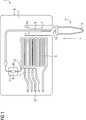
In der
In einer Ausnehmung auf der Rückseite
Über Zu- und Ablauföffnungen
Erfindungsgemäß umfasst der Flachkörper
Über eine Klemmeinrichtung
Die zweite mikrofluidische Einrichtung
Zur einfachen Handhabung einer E-Cup
Die Klemmvorrichtung
In
Die Klemmeinrichtung
Bei Verwendung einer E-Cup
ZITATE ENTHALTEN IN DER BESCHREIBUNG QUOTES INCLUDE IN THE DESCRIPTION
Diese Liste der vom Anmelder aufgeführten Dokumente wurde automatisiert erzeugt und ist ausschließlich zur besseren Information des Lesers aufgenommen. Die Liste ist nicht Bestandteil der deutschen Patent- bzw. Gebrauchsmusteranmeldung. Das DPMA übernimmt keinerlei Haftung für etwaige Fehler oder Auslassungen.This list of the documents listed by the applicant has been generated automatically and is included solely for the better information of the reader. The list is not part of the German patent or utility model application. The DPMA assumes no liability for any errors or omissions.
Zitierte PatentliteraturCited patent literature
- DE 102005049976 A1[0002]DE 102005049976 A1[0002]
Claims (14)
Translated fromGermanPriority Applications (7)
| Application Number | Priority Date | Filing Date | Title |
|---|---|---|---|
| DE102009043226ADE102009043226B4 (en) | 2009-09-28 | 2009-09-28 | Flat body in the manner of a chip card for biochemical analysis and method for its use |
| JP2012530287AJP5430766B2 (en) | 2009-09-28 | 2010-09-27 | Chip card plate for biochemical analysis and method of use thereof |
| CN201080043136.0ACN102548659B (en) | 2009-09-28 | 2010-09-27 | Chip card flat body for biochemical analysis and method of use thereof |
| PCT/EP2010/064258WO2011036289A1 (en) | 2009-09-28 | 2010-09-27 | Flat body in the manner of a chip card for biochemical analysis and method for the use thereof |
| BR112012006831ABR112012006831B1 (en) | 2009-09-28 | 2010-09-27 | flat body in the form of a chip card for biochemical analysis |
| US13/498,871US9415390B2 (en) | 2009-09-28 | 2010-09-27 | Flat body in manner of chip card for biochemical analysis and method of using |
| EP10760321.9AEP2482982B1 (en) | 2009-09-28 | 2010-09-27 | Flat body in the manner of a chip card for biochemical analysis |
Applications Claiming Priority (1)
| Application Number | Priority Date | Filing Date | Title |
|---|---|---|---|
| DE102009043226ADE102009043226B4 (en) | 2009-09-28 | 2009-09-28 | Flat body in the manner of a chip card for biochemical analysis and method for its use |
Publications (2)
| Publication Number | Publication Date |
|---|---|
| DE102009043226A1true DE102009043226A1 (en) | 2011-03-31 |
| DE102009043226B4 DE102009043226B4 (en) | 2012-09-27 |
Family
ID=43302368
Family Applications (1)
| Application Number | Title | Priority Date | Filing Date |
|---|---|---|---|
| DE102009043226AExpired - Fee RelatedDE102009043226B4 (en) | 2009-09-28 | 2009-09-28 | Flat body in the manner of a chip card for biochemical analysis and method for its use |
Country Status (7)
| Country | Link |
|---|---|
| US (1) | US9415390B2 (en) |
| EP (1) | EP2482982B1 (en) |
| JP (1) | JP5430766B2 (en) |
| CN (1) | CN102548659B (en) |
| BR (1) | BR112012006831B1 (en) |
| DE (1) | DE102009043226B4 (en) |
| WO (1) | WO2011036289A1 (en) |
Cited By (2)
| Publication number | Priority date | Publication date | Assignee | Title |
|---|---|---|---|---|
| EP2514528A1 (en)* | 2011-04-19 | 2012-10-24 | Cellix Limited | Device and method for assessing the status of cells in a biological fluid |
| US9415390B2 (en) | 2009-09-28 | 2016-08-16 | Boehringer Ingelheim Vetmedica Gmbh | Flat body in manner of chip card for biochemical analysis and method of using |
Families Citing this family (6)
| Publication number | Priority date | Publication date | Assignee | Title |
|---|---|---|---|---|
| WO2013082316A1 (en)* | 2011-11-29 | 2013-06-06 | Caliper Life Sciences, Inc. | Systems and methods for sampling of amplification products |
| US9689029B2 (en) | 2011-12-02 | 2017-06-27 | Caliper Life Sciences, Inc. | Systems and methods for sampling of amplification products |
| SG11201402709WA (en)* | 2011-12-06 | 2014-06-27 | Univ Bruxelles | Method and device for assaying an antigen present on erythrocytes or an antibody binding to an antigen present on erythrocytes |
| CN104178413B (en)* | 2014-07-04 | 2016-05-25 | 宁波美晶医疗技术有限公司 | A kind of plastic packaging box packaging structure of rare cell separator |
| CN106501499B (en) | 2015-09-07 | 2019-12-17 | 埃克西亚斯医药有限公司 | Movable measuring unit |
| CN110624615B (en)* | 2019-09-19 | 2024-08-06 | 深圳富士凯烨医疗电子科技有限公司 | Microfluidic chip |
Citations (6)
| Publication number | Priority date | Publication date | Assignee | Title |
|---|---|---|---|---|
| US5747666A (en)* | 1997-03-26 | 1998-05-05 | Willis; John P. | Point-of-care analyzer module |
| EP0897750A2 (en)* | 1997-08-19 | 1999-02-24 | bioMerieux Vitek, Inc. | Locking structure for securing a fluid transfer tube |
| DE19964337B4 (en)* | 1999-10-01 | 2004-09-16 | Agilent Technologies, Inc. (n.d.Ges.d.Staates Delaware), Palo Alto | Microfluidic microchip with bendable suction tube |
| US20050130292A1 (en)* | 2003-09-26 | 2005-06-16 | The University Of Cincinnati | Smart disposable plastic lab-on-a-chip for point-of-care testing |
| DE102005049976A1 (en) | 2004-10-15 | 2006-04-20 | Siemens Ag | Cartridge card for automated DNA or protein analysis has a geometric array of micro-channels with dry reagents |
| DE102008004646A1 (en)* | 2007-01-17 | 2008-07-24 | Yokogawa Electric Corporation, Musashino | Chemical reaction cassette and method of use |
Family Cites Families (15)
| Publication number | Priority date | Publication date | Assignee | Title |
|---|---|---|---|---|
| DE19846466A1 (en)* | 1998-10-08 | 2000-04-27 | Ghs Gesundheits Service Ag | Analysis method for the simultaneous determination of parameters from different media |
| CN1117284C (en) | 1999-10-27 | 2003-08-06 | 陆祖宏 | Microfluid biochip detection-analysis board and its detection method |
| US20020009392A1 (en) | 2000-03-28 | 2002-01-24 | Wolk Jeffrey A. | Methods of reducing fluid carryover in microfluidic devices |
| DE10111458B4 (en) | 2001-03-09 | 2008-09-11 | Siemens Ag | analyzer |
| US6913933B2 (en)* | 2001-12-03 | 2005-07-05 | Ortho-Clinical Diagnostics, Inc. | Fluid dispensing algorithm for a variable speed pump driven metering system |
| US8323564B2 (en) | 2004-05-14 | 2012-12-04 | Honeywell International Inc. | Portable sample analyzer system |
| US20060165558A1 (en) | 2004-12-21 | 2006-07-27 | Thomas Witty | Cartridge for diagnostic assays |
| US8206650B2 (en)* | 2005-04-12 | 2012-06-26 | Chromedx Inc. | Joint-diagnostic spectroscopic and biosensor meter |
| WO2007021809A2 (en) | 2005-08-11 | 2007-02-22 | Eksigent Technologies, Llc | Microfluidic systems, devices and methods for reducing background autofluorescence and the effects thereof |
| WO2008002483A2 (en)* | 2006-06-23 | 2008-01-03 | Mcneely Michael R | Reagent preparation and valving design for liquid testing |
| CN101479609B (en) | 2006-06-30 | 2012-09-05 | 松下电器产业株式会社 | Analysis panel and analysis device using same |
| WO2009117167A1 (en) | 2008-01-02 | 2009-09-24 | Blood Cell Storage, Inc. | Devices and processes for nucleic acid extraction |
| US20090186344A1 (en)* | 2008-01-23 | 2009-07-23 | Caliper Life Sciences, Inc. | Devices and methods for detecting and quantitating nucleic acids using size separation of amplicons |
| GB0805296D0 (en)* | 2008-03-20 | 2008-04-30 | Iti Scotland Ltd | Uses of reagents in sample collection and cartridge systems |
| DE102009043226B4 (en) | 2009-09-28 | 2012-09-27 | Siemens Aktiengesellschaft | Flat body in the manner of a chip card for biochemical analysis and method for its use |
- 2009
- 2009-09-28DEDE102009043226Apatent/DE102009043226B4/ennot_activeExpired - Fee Related
- 2010
- 2010-09-27JPJP2012530287Apatent/JP5430766B2/ennot_activeExpired - Fee Related
- 2010-09-27USUS13/498,871patent/US9415390B2/ennot_activeExpired - Fee Related
- 2010-09-27BRBR112012006831Apatent/BR112012006831B1/ennot_activeIP Right Cessation
- 2010-09-27EPEP10760321.9Apatent/EP2482982B1/ennot_activeNot-in-force
- 2010-09-27WOPCT/EP2010/064258patent/WO2011036289A1/enactiveApplication Filing
- 2010-09-27CNCN201080043136.0Apatent/CN102548659B/ennot_activeExpired - Fee Related
Patent Citations (6)
| Publication number | Priority date | Publication date | Assignee | Title |
|---|---|---|---|---|
| US5747666A (en)* | 1997-03-26 | 1998-05-05 | Willis; John P. | Point-of-care analyzer module |
| EP0897750A2 (en)* | 1997-08-19 | 1999-02-24 | bioMerieux Vitek, Inc. | Locking structure for securing a fluid transfer tube |
| DE19964337B4 (en)* | 1999-10-01 | 2004-09-16 | Agilent Technologies, Inc. (n.d.Ges.d.Staates Delaware), Palo Alto | Microfluidic microchip with bendable suction tube |
| US20050130292A1 (en)* | 2003-09-26 | 2005-06-16 | The University Of Cincinnati | Smart disposable plastic lab-on-a-chip for point-of-care testing |
| DE102005049976A1 (en) | 2004-10-15 | 2006-04-20 | Siemens Ag | Cartridge card for automated DNA or protein analysis has a geometric array of micro-channels with dry reagents |
| DE102008004646A1 (en)* | 2007-01-17 | 2008-07-24 | Yokogawa Electric Corporation, Musashino | Chemical reaction cassette and method of use |
Cited By (2)
| Publication number | Priority date | Publication date | Assignee | Title |
|---|---|---|---|---|
| US9415390B2 (en) | 2009-09-28 | 2016-08-16 | Boehringer Ingelheim Vetmedica Gmbh | Flat body in manner of chip card for biochemical analysis and method of using |
| EP2514528A1 (en)* | 2011-04-19 | 2012-10-24 | Cellix Limited | Device and method for assessing the status of cells in a biological fluid |
Also Published As
| Publication number | Publication date |
|---|---|
| EP2482982A1 (en) | 2012-08-08 |
| BR112012006831A8 (en) | 2017-12-05 |
| US20120184043A1 (en) | 2012-07-19 |
| JP2013506123A (en) | 2013-02-21 |
| BR112012006831B1 (en) | 2020-02-04 |
| US9415390B2 (en) | 2016-08-16 |
| WO2011036289A1 (en) | 2011-03-31 |
| EP2482982B1 (en) | 2017-08-16 |
| DE102009043226B4 (en) | 2012-09-27 |
| CN102548659A (en) | 2012-07-04 |
| CN102548659B (en) | 2016-12-07 |
| BR112012006831A2 (en) | 2016-06-07 |
| JP5430766B2 (en) | 2014-03-05 |
Similar Documents
| Publication | Publication Date | Title |
|---|---|---|
| DE102009043226B4 (en) | Flat body in the manner of a chip card for biochemical analysis and method for its use | |
| DE60031526T2 (en) | THRUSTABLE CAP WITH INTERNAL TIP | |
| EP1796838B1 (en) | Method for carrying out an electrochemical measurement on a liquid measuring sample in a measuring chamber that can be accessed by lines | |
| DE102012205171B3 (en) | Integrated disposable chip cartridge system for mobile multi-parameter analysis of chemical and / or biological substances | |
| DE60016415T2 (en) | GENETIC EXPERIMENTAL SYSTEM | |
| DE60210891T2 (en) | Closed microplates | |
| DE102008025992B4 (en) | Titer plate and method for detecting an analyte | |
| EP2654955B1 (en) | Method for mixing at least one sample solution with reagents | |
| DE19546535C2 (en) | Measuring cartridge for liquid or gaseous samples, process for their operation and their use | |
| EP1160573A2 (en) | Microtitre plate and coupled multiple pipettor | |
| WO2019219844A1 (en) | Fluidic system for taking in, dispensing and moving liquids, method for processing fluids in a fluidic system | |
| DE102014200483B4 (en) | Method for operating a microfluidic chip and microfluidic chip | |
| DE102007019695A1 (en) | Cuvette for the optical analysis of small volumes | |
| EP1566215A2 (en) | Microstructured platform and method of handling a liquid | |
| EP1752755B1 (en) | sampling and dosing device with an integrate container for fluid | |
| DE602004009775T2 (en) | Device for reliable analysis | |
| EP4091715A1 (en) | Test strip assembly with containers | |
| EP1641564B1 (en) | Use of a disposable container, microfluidic device and method for processing molecules | |
| EP3669981B1 (en) | Pressure-tight container containing a liquid | |
| EP1542801B1 (en) | Device for determining and displaying at least one physical, chemical or biological property of a test liquid | |
| DE102017206489A1 (en) | Apparatus and method for a microfluidic system for analyzing a sample | |
| WO2015062715A1 (en) | Improved device and method for reactions between a solid and a liquid phase | |
| EP2243024B1 (en) | Apparatus and method for the detection of liquids or substances from liquids | |
| DE102013200466B4 (en) | Analysis device and analysis method for analyzing an analyte | |
| DE102018102383B4 (en) | System for carrying out biological or chemical processes |
Legal Events
| Date | Code | Title | Description |
|---|---|---|---|
| OP8 | Request for examination as to paragraph 44 patent law | ||
| R016 | Response to examination communication | ||
| R016 | Response to examination communication | ||
| R016 | Response to examination communication | ||
| R016 | Response to examination communication | ||
| R016 | Response to examination communication | ||
| R018 | Grant decision by examination section/examining division | ||
| R020 | Patent grant now final | Effective date:20121228 | |
| R081 | Change of applicant/patentee | Owner name:BOEHRINGER INGELHEIM VETMEDICA GMBH, DE Free format text:FORMER OWNER: SIEMENS AKTIENGESELLSCHAFT, 80333 MUENCHEN, DE Effective date:20140612 | |
| R119 | Application deemed withdrawn, or ip right lapsed, due to non-payment of renewal fee |