DE102009039484A1 - Coil system for a magnetically guided capsule endoscopy - Google Patents
Coil system for a magnetically guided capsule endoscopyDownload PDFInfo
- Publication number
- DE102009039484A1 DE102009039484A1DE102009039484ADE102009039484ADE102009039484A1DE 102009039484 A1DE102009039484 A1DE 102009039484A1DE 102009039484 ADE102009039484 ADE 102009039484ADE 102009039484 ADE102009039484 ADE 102009039484ADE 102009039484 A1DE102009039484 A1DE 102009039484A1
- Authority
- DE
- Germany
- Prior art keywords
- coil
- plane
- coil system
- central
- coils
- Prior art date
- Legal status (The legal status is an assumption and is not a legal conclusion. Google has not performed a legal analysis and makes no representation as to the accuracy of the status listed.)
- Withdrawn
Links
- 239000002775capsuleSubstances0.000titleclaimsabstractdescription25
- 238000001839endoscopyMethods0.000titleclaimsabstractdescription14
- 238000004804windingMethods0.000claimsdescription14
- 238000001816coolingMethods0.000claimsdescription5
- XLYOFNOQVPJJNP-UHFFFAOYSA-NwaterSubstancesOXLYOFNOQVPJJNP-UHFFFAOYSA-N0.000description5
- 210000002784stomachAnatomy0.000description4
- RYGMFSIKBFXOCR-UHFFFAOYSA-NCopperChemical compound[Cu]RYGMFSIKBFXOCR-UHFFFAOYSA-N0.000description3
- 229910052802copperInorganic materials0.000description3
- 239000010949copperSubstances0.000description3
- XAGFODPZIPBFFR-UHFFFAOYSA-NaluminiumChemical compound[Al]XAGFODPZIPBFFR-UHFFFAOYSA-N0.000description2
- 229910052782aluminiumInorganic materials0.000description2
- 210000001198duodenumAnatomy0.000description2
- BUHVIAUBTBOHAG-FOYDDCNASA-N(2r,3r,4s,5r)-2-[6-[[2-(3,5-dimethoxyphenyl)-2-(2-methylphenyl)ethyl]amino]purin-9-yl]-5-(hydroxymethyl)oxolane-3,4-diolChemical compoundCOC1=CC(OC)=CC(C(CNC=2C=3N=CN(C=3N=CN=2)[C@H]2[C@@H]([C@H](O)[C@@H](CO)O2)O)C=2C(=CC=CC=2)C)=C1BUHVIAUBTBOHAG-FOYDDCNASA-N0.000description1
- 210000003238esophagusAnatomy0.000description1
- XUFQPHANEAPEMJ-UHFFFAOYSA-NfamotidineChemical compoundNC(N)=NC1=NC(CSCCC(N)=NS(N)(=O)=O)=CS1XUFQPHANEAPEMJ-UHFFFAOYSA-N0.000description1
- 210000001035gastrointestinal tractAnatomy0.000description1
- 230000005484gravityEffects0.000description1
- 238000004519manufacturing processMethods0.000description1
- 238000000034methodMethods0.000description1
Images
Classifications
- A—HUMAN NECESSITIES
- A61—MEDICAL OR VETERINARY SCIENCE; HYGIENE
- A61B—DIAGNOSIS; SURGERY; IDENTIFICATION
- A61B34/00—Computer-aided surgery; Manipulators or robots specially adapted for use in surgery
- A61B34/30—Surgical robots
- A—HUMAN NECESSITIES
- A61—MEDICAL OR VETERINARY SCIENCE; HYGIENE
- A61B—DIAGNOSIS; SURGERY; IDENTIFICATION
- A61B1/00—Instruments for performing medical examinations of the interior of cavities or tubes of the body by visual or photographical inspection, e.g. endoscopes; Illuminating arrangements therefor
- A61B1/005—Flexible endoscopes
- A61B1/01—Guiding arrangements therefore
- A—HUMAN NECESSITIES
- A61—MEDICAL OR VETERINARY SCIENCE; HYGIENE
- A61B—DIAGNOSIS; SURGERY; IDENTIFICATION
- A61B1/00—Instruments for performing medical examinations of the interior of cavities or tubes of the body by visual or photographical inspection, e.g. endoscopes; Illuminating arrangements therefor
- A61B1/12—Instruments for performing medical examinations of the interior of cavities or tubes of the body by visual or photographical inspection, e.g. endoscopes; Illuminating arrangements therefor with cooling or rinsing arrangements
- A—HUMAN NECESSITIES
- A61—MEDICAL OR VETERINARY SCIENCE; HYGIENE
- A61B—DIAGNOSIS; SURGERY; IDENTIFICATION
- A61B34/00—Computer-aided surgery; Manipulators or robots specially adapted for use in surgery
- A61B34/70—Manipulators specially adapted for use in surgery
- A—HUMAN NECESSITIES
- A61—MEDICAL OR VETERINARY SCIENCE; HYGIENE
- A61B—DIAGNOSIS; SURGERY; IDENTIFICATION
- A61B34/00—Computer-aided surgery; Manipulators or robots specially adapted for use in surgery
- A61B34/70—Manipulators specially adapted for use in surgery
- A61B34/73—Manipulators for magnetic surgery
- A61B2034/731—Arrangement of the coils or magnets
- A61B2034/733—Arrangement of the coils or magnets arranged only on one side of the patient, e.g. under a table
Landscapes
- Health & Medical Sciences (AREA)
- Life Sciences & Earth Sciences (AREA)
- Surgery (AREA)
- Engineering & Computer Science (AREA)
- Animal Behavior & Ethology (AREA)
- Veterinary Medicine (AREA)
- Biomedical Technology (AREA)
- Heart & Thoracic Surgery (AREA)
- Medical Informatics (AREA)
- Molecular Biology (AREA)
- Nuclear Medicine, Radiotherapy & Molecular Imaging (AREA)
- General Health & Medical Sciences (AREA)
- Public Health (AREA)
- Robotics (AREA)
- Physics & Mathematics (AREA)
- Biophysics (AREA)
- Optics & Photonics (AREA)
- Pathology (AREA)
- Radiology & Medical Imaging (AREA)
- Magnetic Resonance Imaging Apparatus (AREA)
- Endoscopes (AREA)
- Measurement Of The Respiration, Hearing Ability, Form, And Blood Characteristics Of Living Organisms (AREA)
Abstract
Translated fromGermanDescription
Translated fromGermanDie Erfindung betrifft ein Spulensystem, mit dessen Hilfe eine magnetisch geführte Kapselendoskopie an einem Patienten durchführbar ist.The invention relates to a coil system, by means of which a magnetically guided capsule endoscopy on a patient is feasible.
Bei der magnetisch geführten Kapselendoskopie (MGCE) wird eine Endoskopiekapsel, welche verschiedene medizinische Aufgaben erfüllen kann, in einen Patienten eingebracht. Die Kapsel enthält ein magnetisches Element, mittels dessen durch Anlegen eines äußeren Magnetfeldes eine Kraft bzw. Drehmoment auf die Kapsel ausgeübt werden kann. Durch gezielte Krafteinwirkung kann die Kapsel im Patienten berührungslos fortbewegt werden und dort entsprechend medizinische Aufgaben erfüllen.Magnetic guided capsule endoscopy (MGCE) introduces an endoscopy capsule that can perform various medical tasks into a patient. The capsule contains a magnetic element, by means of which by applying an external magnetic field, a force or torque can be exerted on the capsule. Through targeted application of force, the capsule can be moved without contact in the patient and there correspondingly fulfill medical tasks.
Das äußere Magnetfeld zur Kraftausübung auf die Kapsel wird von einem außerhalb des Patienten angeordneten sogenannten Führungsmagneten (Guidance Magnet) erzeugt. Ein entsprechendes Spulensystem ist z. B. aus der
Die vorliegende Erfindung befasst sich mit einer speziellen Anwendung der MGCE, nämlich der Ösophagus-Gaster-Duodenum(deutsch: ÖGD/englisch: EGD)-Endoskopie, bei welcher eben lediglich Speiseröhre und Magen und gegebenenfalls auch der Zwölffingerdarm eines Patienten mit Hilfe der Kapselendoskopie erreichbar sind.The present invention is concerned with a specific application of MGCE, namely the esophageal gaster duodenum (German: ÖGD / English: EGD) endoscopy, in which just only the esophagus and stomach and possibly also the duodenum of a patient can be reached with the help of capsule endoscopy are.
Für eine derartige ÖGD-Untersuchung wird der Magen z. B. zur Hälfte oder mehr mit Wasser gefüllt. Die Kapsel hat ein Volumen von ca. 2–3 cm3. Die Endoskopiekapsel mit einer Masse von ca. 2–3 g wird mit einer entsprechenden Dichte ausgeführt, welche nahe, bevorzugt knapp unterhalb der von Wasser ist.For such an ÖGD examination, the stomach is z. B. half or more filled with water. The capsule has a volume of about 2-3 cm3 . The endoscopy capsule with a mass of about 2-3 g is performed with a corresponding density, which is close, preferably just below that of water.
Die Endoskopiekapsel schwimmt dann im Magen im Wasser und hat dabei zusammen mit ihrem Auftrieb eine effektive Masse von z. B. –0,1 g. Die Einbauten in der Kapsel sind so angeordnet, dass sich der Schwerpunkt der Kapsel auf der Kapsellängsachse ein Stück entfernt vom Kapselmittelpunkt befindet. Die länglich geformte Kapsel steht daher im Wasser ohne äußere Krafteinwirkung senkrecht, deren an der Spitze eingebaute Kamera weist im Ruhezustand nach unten.The endoscopy capsule then floats in the stomach in the water and has, together with its buoyancy an effective mass of z. B. -0.1 g. The internals in the capsule are arranged so that the center of gravity of the capsule is located on the capsule longitudinal axis a distance away from the capsule center. The elongated shaped capsule is therefore vertically in the water without external force, the built-in tip of the camera has at rest down.
Durch einen entsprechenden Führungsmagneten kann die Kapsel gegen deren Auftrieb im Magen von der Wasseroberfläche nach unten gezogen werden, horizontal verfahren und gekippt werden. Bei dieser entsprechenden Spezialanwendung der MGCE sind nur wesentlich geringere Kräfte auf die Kapsel auszuüben, als wenn diese durch den gesamten Intestinaltrakt des Patienten bewegt werden soll.By a corresponding guide magnet, the capsule can be pulled down against the buoyancy in the stomach of the water surface, moved horizontally and tilted. In this particular special application of the MGCE, only much lower forces are exerted on the capsule than if it is to be moved through the entire intestinal tract of the patient.
Im Vergleich zum oben genannten allgemeinen Spulensystem wird für die vorliegende ÖGD-Anwendung daher nur ein sogenannter ÖGD-Führungsmagnet (englisch: EGD Guidance Magnet) verwendet, welcher wesentlich einfacher aufgebaut sein kann als der in der
Darüber hinaus ist aus der
Aufgabe der vorliegenden Erfindung ist es, ein weiter verbessertes Spulensystem für eine magnetisch geführte Kapselendoskopie anzugeben.The object of the present invention is to provide a further improved coil system for a magnetically guided capsule endoscopy.
Die Aufgabe wird gelöst durch ein Spulensystem gemäß Patentanspruch 1, welches zur Erzeugung der Magnetfelder für eine magnetisch geführte Kapselendoskopie dient. Das Spulensystem weist folgende Komponenten auf, wobei sämtliche Komponenten unter, d. h. an der Unterseite eines Patiententisches angeordnet sind, wobei auf der Oberseite ein Patient lagerbar ist. Die Platte des Patiententisches definiert hierbei eine – in der Regel horizontale – Planebene, muss aber selbst nicht plan sein. Die Planebene kann z. B. über die Außenlängskanten des Patiententisches definiert sein.The object is achieved by a coil system according to claim 1, which serves to generate the magnetic fields for a magnetically guided capsule endoscopy. The coil system has the following components, wherein all components below, d. H. are arranged on the underside of a patient table, wherein on the top of a patient is storable. The plate of the patient table defines this - usually horizontal - Plane level, but does not have to be even plan. The plane can z. B. defined over the outer longitudinal edges of the patient table.
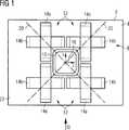
Das Spulensystem umfasst eine Zentralspule, deren Normalenrichtung senkrecht zur Planebene steht. Mit anderen Worten ist die Zentralspule parallel unterhalb des Patiententisches angeordnet. Das Spulensystem weist außerdem vier ebenfalls unter dem Tisch angeordnete Spulenpaare auf, welche kreuzweise um die zentrale Spule herum angeordnet sind. Jedes Spulenpaar umfasst zwei Einzelspulen, deren Normalenrichtungen parallel zur Planebene verlaufen und zusätzlich zueinander um 90° versetzt orientiert sind. Mit anderen Worten bestehen die Spulenpaare also aus gekreuzten, jeweils senkrecht zur Zentralspule stehenden Einzelspulen. Die Zentralspule und ein Spulenpaar stehen damit paarweise aufeinander senkrecht und decken damit alle Raumrichtungen für magentische Felder ab. Oberhalb und seitlich des Patiententisches befinden sich keine Spulen.The coil system comprises a central coil whose normal direction is perpendicular to the plane Plane. In other words, the central coil is arranged parallel below the patient table. The coil system also has four coil pairs also arranged under the table, which are arranged crosswise around the central coil. Each coil pair comprises two individual coils whose normal directions are parallel to the plane of the plane and are additionally oriented offset by 90 ° relative to one another. In other words, the coil pairs thus consist of crossed, each perpendicular to the central coil individual coils. The central coil and a coil pair are thus perpendicular to each other in pairs and thus cover all spatial directions for magenta fields. There are no coils above and at the side of the patient table.
Zur Erläuterung sei ein kartesisches Koordinatensystem (x, y, z) angenommen: Der Patiententisch liegt mit seiner horizontalen Planebene in der (x, z)-Ebene des Koordinatensystems. Die y-Richtung bildet die Vertikale und also die Flächennormale am Patiententisch. Die Zentralspule ist dann auch in y-Richtung orientiert, d. h. die Flächennormale der von der Spule umgespannten Ebene zeigt in y-Richtung. Die Einzelspulen der Spulenpaare sind entsprechend jeweils in x- und z-Richtung orientiert.For explanation, assume a Cartesian coordinate system (x, y, z): The patient table lies with its horizontal plane plane in the (x, z) plane of the coordinate system. The y-direction forms the vertical and thus the surface normal at the patient table. The central coil is then oriented in the y-direction, d. H. the surface normal of the plane spanned by the coil points in the y-direction. The individual coils of the coil pairs are respectively oriented in the x and z directions.
Die Erfindung besteht damit in der Idee bzw. Konzeption der Spulengeometrie und -anordnung. Es ergibt sich eine maximale Patientenzugänglichkeit während einer Untersuchung bzw. Prozedur, welche am Patienten auszuführen ist, weil der Magnet, also das gesamte Spulensystem, vollständig unter der Patientenliege angeordnet bzw. „versteckt” ist. Das erfindungsgemäße Spulensystem umfasst nur neun Spulen im Gegensatz zu 10 oder 12 Spulen der bekannten Systeme. Im Gegensatz zum o. g. bekannten Konzept des Blockmagneten ist das Spulensystem starr angeordnet, d. h. der Guidance Magnet enthält keine mechanisch beweglichen Teile.The invention thus consists in the idea or conception of the coil geometry and arrangement. This results in a maximum patient accessibility during an examination or procedure which is to be performed on the patient because the magnet, ie the entire coil system, is completely arranged or "hidden" under the patient bed. The coil system according to the invention comprises only nine coils in contrast to 10 or 12 coils of the known systems. In contrast to the o. G. known concept of the block magnet, the coil system is rigidly arranged, d. H. The Guidance Magnet contains no mechanical moving parts.
Gegenüber einem System, welches den Patienten umschließt müssen allerdings Verstärker höherer maximaler Stromstärke und Leistung von ca. 350 A bzw. 40 kW im Vergleich zu 90 A bzw. 10 kW für die Spulen eingesetzt werden.However, compared to a system which encloses the patient, amplifiers of higher maximum current and power of approximately 350 A or 40 kW must be used in comparison to 90 A or 10 kW for the coils.
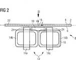
Jede Einzelspule eines Spulenpaares weist einen Abschnitt auf, welcher der Planebene am nächsten gelegen ist, also sich nächstliegend an der Planebene befindet. In einer bevorzugten Ausführungsform der Erfindung verläuft dieser Abschnitt parallel zur Planebene. Die Einzelspule weist somit zumindest einen planen Abschnitt auf, der möglichst nahe am Patiententisch angeordnet ist und somit ein möglichst starkes Feld im Bereich des Patienten erzeugen kann. Die restlichen Spulenteile entfernen sich von der Planebene bzw. dem Patiententisch, und deren Feldanteile treten an der Oberseite des Patiententisches in den Hintergrund.Each individual coil of a coil pair has a section which is closest to the plane of the plane, that is, is located closest to the plane of the plane. In a preferred embodiment of the invention, this section is parallel to the plane Plane. The individual coil thus has at least one planar section, which is arranged as close as possible to the patient table and thus can generate the strongest possible field in the region of the patient. The remaining coil parts move away from the plane plane or the patient table, and their field shares occur at the top of the patient table in the background.
In einer weiteren bevorzugten Ausführungsform weisen die Zentralspule und/oder die Einzelspulen eine rechteckige Form mit abgerundeten Ecken auf. Die Wicklung der Spulen verläuft also entlang einer Kurve, die annähernd ein Rechteck beschreibt bzw. die von der Wicklung umgrenzte Fläche ist annähernd rechteckig. Insbesondere für die Einzelspulen verfügen diese dann über eine Seiten, also einen Abschnitt, welche nächstliegend der Planebene bzw. Patientenliege angeordnet ist und parallel zu dieser verläuft. An diesen Abschnitt schließen sich dann die beiden senkrecht hierzu verlaufenden Seiten des Rechtecks an, welche jedoch wegen des 90° Winkels im Rechteck um 90° versetzte Feldkomponenten erzeugen. Die vierte Seite des Rechteckes ist dann von der Planebene möglichst weit entfernt, um das vom ersten Abschnitt erzeugte Feld praktisch nur noch geringfügig zu schwächen.In a further preferred embodiment, the central coil and / or the individual coils have a rectangular shape with rounded corners. The winding of the coils thus runs along a curve which describes approximately a rectangle or the area delimited by the winding is approximately rectangular. In particular for the individual coils, these then have one side, that is to say a section which is arranged closest to the plane plane or patient couch and runs parallel to it. This section is then followed by the two sides of the rectangle running perpendicularly to it, which, however, produce 90 ° field components due to the 90 ° angle in the rectangle. The fourth side of the rectangle is then as far as possible from the plane Plane, in order to weaken the field generated by the first section practically only slightly.
Bei der Ausführung der Zentralspule als Rechteck oder Quadrat können insbesondere die vier Spulenpaare kreuzweise an den Ecken der Zentralspule angeordnet sein. Die Einzelspulen sind dann parallel zu den jeweiligen Seiten der rechteckigen Zentralspule ausgerichtet.In the embodiment of the central coil as a rectangle or square, in particular, the four coil pairs can be arranged crosswise at the corners of the central coil. The individual coils are then aligned parallel to the respective sides of the rectangular central coil.
In einer weiteren bevorzugten Ausführungsform der Erfindung ist die jeweils eine Einzelspule eines Spulenpaares in die jeweils andere Einzelspule eingesteckt. Die Herstellung des Spulenpaares ist dadurch besonders einfach möglich, da keine Überkreuzung der Wicklungen nötig ist.In a further preferred embodiment of the invention, the respective one individual coil of a coil pair is inserted into the respective other individual coil. The production of the coil pair is particularly easy because no crossover of the windings is necessary.
In einer weiteren vorteilhaften Ausführungsform der Erfindung weisen alle Spulenpaare gleich Ausrichtung auf. Mit obiger Nomenklatur einer in y-Richtung orientierten Zentralspule sind dann beispielsweise sämtliche erste Spulen der vier Spulenpaare in x-Richtung und sämtliche zweiten Spulen der vier Spulenpaare in z-Richtung ausgerichtet. So entsteht eine äußert symmetrische Anordnung.In a further advantageous embodiment of the invention, all coil pairs have the same orientation. With the above nomenclature of a center coil oriented in the y direction, all the first coils of the four coil pairs are then aligned in the x direction and all the second coils of the four coil pairs are aligned in the z direction, for example. This creates an extremely symmetrical arrangement.
In einer weiteren bevorzugten Ausführungsform ist die Zentralspule und/oder die Einzelspule eine Racetrackspule. Racetrackspulen sind eben und können beispielsweise als Aluminium oder Kupferbandwicklung ausgeführt werden.In a further preferred embodiment, the central coil and / or the individual coil is a racetrack coil. Racetrack coils are flat and can be made, for example, as aluminum or copper tape winding.
In einer bevorzugten Variante weist daher die Racetrackspule eine Bandwicklung auf.In a preferred variant, therefore, the Racetrackspule on a tape winding.
In einer bevorzugten Ausführungsform erfolgt eine Kühlung der Bandwicklung an einer oder an beiden Seitenflächen der Bandwicklung. Bei einseitiger Kühlung erfolgt die Kühlung an derjenigen Seite der Bandwicklung, so dass sich ein möglichst kompaktes Design der Spulenanordnung bei größtmöglicher Nähe zum Arbeitsvolumen ergibt.In a preferred embodiment, the tape winding is cooled on one or both side surfaces of the tape winding. With one-sided cooling, the cooling takes place on that side of the tape winding, so that the most compact possible design of the coil assembly results in the greatest possible proximity to the working volume.
Für eine weitere Beschreibung der Erfindung wird auf die Ausführungsbeispiele der Zeichnungen verwiesen. Es zeigen, jeweils in einer schematischen Prinzipskizze:For a further description of the invention reference is made to the embodiments of the drawings. They show, in each case in a schematic outline sketch:
Die
Das Spulensystem
In einer alternativen, nicht dargestellten Ausführungsform sind die Spulen
Alle Spulen sind als sogenannte Racetrackspulen ausgeführt, d. h. sie sind eben und mit einer Aluminium- oder Kupferbandwicklung ausgeführt. Die im Folgenden angegebenen Spulenabmessungen beziehen sich auf eine Kupferwicklung – welche nicht notwendigerweise eine Bandwicklung sein muss – mit einem angenommenen Füllfaktor einschließlich Kühlung von 85%. Die Außenabmessungen der Zentralspule
Die Einzelspulen
In
In
ZITATE ENTHALTEN IN DER BESCHREIBUNG QUOTES INCLUDE IN THE DESCRIPTION
Diese Liste der vom Anmelder aufgeführten Dokumente wurde automatisiert erzeugt und ist ausschließlich zur besseren Information des Lesers aufgenommen. Die Liste ist nicht Bestandteil der deutschen Patent- bzw. Gebrauchsmusteranmeldung. Das DPMA übernimmt keinerlei Haftung für etwaige Fehler oder Auslassungen.This list of the documents listed by the applicant has been generated automatically and is included solely for the better information of the reader. The list is not part of the German patent or utility model application. The DPMA assumes no liability for any errors or omissions.
Zitierte PatentliteraturCited patent literature
- DE 10340925 B3[0003, 0008]DE 10340925 B3[0003, 0008]
- DE 102008004871 A1[0008]DE 102008004871 A1[0008]
- DE 102007007801 A1[0008]DE 102007007801 A1[0008]
- WO 2006/014011 A1[0009]WO 2006/014011 A1[0009]
Claims (8)
Translated fromGermanPriority Applications (7)
| Application Number | Priority Date | Filing Date | Title |
|---|---|---|---|
| DE102009039484ADE102009039484A1 (en) | 2009-08-31 | 2009-08-31 | Coil system for a magnetically guided capsule endoscopy |
| EP10757177.0AEP2473129B1 (en) | 2009-08-31 | 2010-08-25 | Solenoid system for magnetically guided capsule endoscopy |
| JP2012526043AJP5506930B2 (en) | 2009-08-31 | 2010-08-25 | Coil system for magnetically guided capsule endoscope |
| US13/393,417US9283044B2 (en) | 2009-08-31 | 2010-08-25 | Solenoid system for magnetically guided capsule endoscopy |
| KR1020127008353AKR101314484B1 (en) | 2009-08-31 | 2010-08-25 | Solenoid system for magnetically guided capsule endoscopy |
| CN201080038717.5ACN102481174B (en) | 2009-08-31 | 2010-08-25 | Solenoid system for magnetically guided capsule endoscopy |
| PCT/EP2010/062365WO2011023710A1 (en) | 2009-08-31 | 2010-08-25 | Solenoid system for magnetically guided capsule endoscopy |
Applications Claiming Priority (1)
| Application Number | Priority Date | Filing Date | Title |
|---|---|---|---|
| DE102009039484ADE102009039484A1 (en) | 2009-08-31 | 2009-08-31 | Coil system for a magnetically guided capsule endoscopy |
Publications (2)
| Publication Number | Publication Date |
|---|---|
| DE102009039484A1true DE102009039484A1 (en) | 2011-03-03 |
| DE102009039484A8 DE102009039484A8 (en) | 2011-06-01 |
Family
ID=43416551
Family Applications (1)
| Application Number | Title | Priority Date | Filing Date |
|---|---|---|---|
| DE102009039484AWithdrawnDE102009039484A1 (en) | 2009-08-31 | 2009-08-31 | Coil system for a magnetically guided capsule endoscopy |
Country Status (7)
| Country | Link |
|---|---|
| US (1) | US9283044B2 (en) |
| EP (1) | EP2473129B1 (en) |
| JP (1) | JP5506930B2 (en) |
| KR (1) | KR101314484B1 (en) |
| CN (1) | CN102481174B (en) |
| DE (1) | DE102009039484A1 (en) |
| WO (1) | WO2011023710A1 (en) |
Cited By (1)
| Publication number | Priority date | Publication date | Assignee | Title |
|---|---|---|---|---|
| US9283044B2 (en) | 2009-08-31 | 2016-03-15 | Siemens Aktiengesellschaft | Solenoid system for magnetically guided capsule endoscopy |
Families Citing this family (5)
| Publication number | Priority date | Publication date | Assignee | Title |
|---|---|---|---|---|
| WO2014063048A1 (en)* | 2012-10-18 | 2014-04-24 | University Of Utah Research Foundation | Omnidirectional electromagnet |
| JP6376847B2 (en)* | 2014-05-31 | 2018-08-22 | 株式会社ミュー | Medical equipment |
| KR102260162B1 (en)* | 2019-10-21 | 2021-06-03 | 전남대학교산학협력단 | Apparatus for Controlling Micro Robot |
| US11883007B2 (en) | 2021-08-07 | 2024-01-30 | Brian Michael Coyle | Controlled motion capsule |
| KR102436113B1 (en)* | 2021-11-02 | 2022-08-25 | 주식회사 아임시스템 | Magnetic field generator for precision procedure |
Citations (6)
| Publication number | Priority date | Publication date | Assignee | Title |
|---|---|---|---|---|
| WO2002049705A1 (en)* | 2000-12-21 | 2002-06-27 | Oxford Instruments Plc | Magnetic field generating system and method |
| US20040244636A1 (en)* | 2003-06-06 | 2004-12-09 | Magno Corporation | Adaptive magnetic levitation apparatus and method |
| DE10340925B3 (en) | 2003-09-05 | 2005-06-30 | Siemens Ag | Magnetic coil system for non-contact movement of a magnetic body in a working space |
| WO2006014011A1 (en) | 2004-08-03 | 2006-02-09 | Olympus Corporation | Magnetic guiding medical system |
| DE102007007801A1 (en) | 2007-02-16 | 2008-08-21 | Siemens Ag | Magnetic coil system with a navigation coil system and a location system |
| DE102008004871A1 (en) | 2008-01-17 | 2009-07-30 | Siemens Aktiengesellschaft | Coil arrangement for guiding a magnetic element in a working space |
Family Cites Families (11)
| Publication number | Priority date | Publication date | Assignee | Title |
|---|---|---|---|---|
| GB1035205A (en)* | 1962-11-30 | 1966-07-06 | Yeda Res & Dev | Improvements in the remote controlled propulsion of a body |
| US5592939A (en)* | 1995-06-14 | 1997-01-14 | Martinelli; Michael A. | Method and system for navigating a catheter probe |
| AU1240801A (en)* | 1999-10-28 | 2001-05-08 | Enterprise Medical Technology, Inc. | Coil structures and methods for generating magnetic fields |
| US6493573B1 (en)* | 1999-10-28 | 2002-12-10 | Winchester Development Associates | Method and system for navigating a catheter probe in the presence of field-influencing objects |
| JP4426875B2 (en)* | 2004-03-08 | 2010-03-03 | オリンパス株式会社 | Capsule medical device magnetic guidance system |
| US7751866B2 (en) | 2004-03-08 | 2010-07-06 | Olympus Corporation | Detecting system of position and posture of capsule medical device |
| EP1969989B1 (en) | 2005-12-28 | 2016-12-14 | Olympus Corporation | Body-insertable device system and in-vivo observation method |
| JP4668967B2 (en) | 2007-09-26 | 2011-04-13 | オリンパス株式会社 | Capsule type medical device direction detection system |
| US8235888B2 (en)* | 2008-07-08 | 2012-08-07 | Olympus Medical Systems Corp. | System for guiding capsule medical device |
| DE102009039484A1 (en) | 2009-08-31 | 2011-03-03 | Siemens Aktiengesellschaft | Coil system for a magnetically guided capsule endoscopy |
| JP4932971B2 (en)* | 2010-03-26 | 2012-05-16 | オリンパスメディカルシステムズ株式会社 | Capsule type medical device guidance system |
- 2009
- 2009-08-31DEDE102009039484Apatent/DE102009039484A1/ennot_activeWithdrawn
- 2010
- 2010-08-25WOPCT/EP2010/062365patent/WO2011023710A1/enactiveApplication Filing
- 2010-08-25EPEP10757177.0Apatent/EP2473129B1/ennot_activeNot-in-force
- 2010-08-25CNCN201080038717.5Apatent/CN102481174B/ennot_activeExpired - Fee Related
- 2010-08-25KRKR1020127008353Apatent/KR101314484B1/ennot_activeExpired - Fee Related
- 2010-08-25JPJP2012526043Apatent/JP5506930B2/ennot_activeExpired - Fee Related
- 2010-08-25USUS13/393,417patent/US9283044B2/ennot_activeExpired - Fee Related
Patent Citations (6)
| Publication number | Priority date | Publication date | Assignee | Title |
|---|---|---|---|---|
| WO2002049705A1 (en)* | 2000-12-21 | 2002-06-27 | Oxford Instruments Plc | Magnetic field generating system and method |
| US20040244636A1 (en)* | 2003-06-06 | 2004-12-09 | Magno Corporation | Adaptive magnetic levitation apparatus and method |
| DE10340925B3 (en) | 2003-09-05 | 2005-06-30 | Siemens Ag | Magnetic coil system for non-contact movement of a magnetic body in a working space |
| WO2006014011A1 (en) | 2004-08-03 | 2006-02-09 | Olympus Corporation | Magnetic guiding medical system |
| DE102007007801A1 (en) | 2007-02-16 | 2008-08-21 | Siemens Ag | Magnetic coil system with a navigation coil system and a location system |
| DE102008004871A1 (en) | 2008-01-17 | 2009-07-30 | Siemens Aktiengesellschaft | Coil arrangement for guiding a magnetic element in a working space |
Cited By (1)
| Publication number | Priority date | Publication date | Assignee | Title |
|---|---|---|---|---|
| US9283044B2 (en) | 2009-08-31 | 2016-03-15 | Siemens Aktiengesellschaft | Solenoid system for magnetically guided capsule endoscopy |
Also Published As
| Publication number | Publication date |
|---|---|
| JP2013502953A (en) | 2013-01-31 |
| JP5506930B2 (en) | 2014-05-28 |
| DE102009039484A8 (en) | 2011-06-01 |
| US20120232337A1 (en) | 2012-09-13 |
| US9283044B2 (en) | 2016-03-15 |
| CN102481174B (en) | 2015-04-08 |
| CN102481174A (en) | 2012-05-30 |
| EP2473129B1 (en) | 2013-11-20 |
| EP2473129A1 (en) | 2012-07-11 |
| WO2011023710A1 (en) | 2011-03-03 |
| KR101314484B1 (en) | 2013-10-07 |
| KR20120062858A (en) | 2012-06-14 |
Similar Documents
| Publication | Publication Date | Title |
|---|---|---|
| DE10340925B3 (en) | Magnetic coil system for non-contact movement of a magnetic body in a working space | |
| EP2473129B1 (en) | Solenoid system for magnetically guided capsule endoscopy | |
| DE10241178B4 (en) | Isokinetic gantry arrangement for the isocentric guidance of a particle beam and method for its design | |
| DE102005010489B4 (en) | Coil system for non-contact magnetic navigation of a magnetic body in a patient located in a working space | |
| DE102012211590B4 (en) | Fixed connection module for HF control in a mass spectrometer | |
| DE102008004871A1 (en) | Coil arrangement for guiding a magnetic element in a working space | |
| DE102010027954A1 (en) | Guide with passive gravity compensation and vertically movable platform | |
| DE102009013352B4 (en) | Coil arrangements for guiding a magnetic object in a working space | |
| DE102009004899B4 (en) | Superconducting actively shielded magnet | |
| WO2012156278A1 (en) | Device for producing a homogenous magnetic field | |
| DE10334079B4 (en) | transistor module | |
| DE102007046508A1 (en) | Irradiation plant with a beam guiding magnet | |
| DE112018002149T5 (en) | FLEXIBLE POKE HOME CONTACT | |
| DE19628363A1 (en) | MR arrangement | |
| DE707379C (en) | DF antenna system with ferromagnetic core | |
| DE3105310A1 (en) | CATHODE RAY TUBE | |
| DE930887C (en) | Arrangement for practicing a method for operating run-time tubes | |
| DE102008064379A1 (en) | Magnetic coil arrangement with fixed and movable coils | |
| DE102011004825A1 (en) | Method and device for controlling the transport of a magnetic moment endoscope capsule | |
| DE202020107456U1 (en) | Coupled magnetic element with high dielectric strength and high power density | |
| DE10160610B4 (en) | Filters for an X-ray examination device for absorbing X-rays and medical X-ray device with such a filter | |
| EP3921859A1 (en) | Secondary coil topology | |
| DE112019006978T5 (en) | Charged particle beam device | |
| DE202012100245U1 (en) | Device for generating magnetic fields for magnetic field therapy | |
| DE102007025584B4 (en) | A radiation guide magnet for deflecting a beam of electrically charged particles along a curved particle track and irradiation system with such a magnet |
Legal Events
| Date | Code | Title | Description |
|---|---|---|---|
| OP8 | Request for examination as to paragraph 44 patent law | ||
| 8196 | Reprint of faulty title page (publication) german patentblatt: part 1a6 | ||
| OP8 | Request for examination as to paragraph 44 patent law | ||
| R016 | Response to examination communication | ||
| R079 | Amendment of ipc main class | Free format text:PREVIOUS MAIN CLASS: A61B0019000000 Ipc:A61B0034200000 | |
| R119 | Application deemed withdrawn, or ip right lapsed, due to non-payment of renewal fee |