DE102009039341A1 - tracking device - Google Patents
tracking deviceDownload PDFInfo
- Publication number
- DE102009039341A1 DE102009039341A1DE102009039341ADE102009039341ADE102009039341A1DE 102009039341 A1DE102009039341 A1DE 102009039341A1DE 102009039341 ADE102009039341 ADE 102009039341ADE 102009039341 ADE102009039341 ADE 102009039341ADE 102009039341 A1DE102009039341 A1DE 102009039341A1
- Authority
- DE
- Germany
- Prior art keywords
- housing
- tracking device
- shaft
- console
- hydraulic
- Prior art date
- Legal status (The legal status is an assumption and is not a legal conclusion. Google has not performed a legal analysis and makes no representation as to the accuracy of the status listed.)
- Withdrawn
Links
- 238000003860storageMethods0.000claimsabstractdescription6
- 241000237858GastropodaSpecies0.000claimsdescription5
- 230000001360synchronised effectEffects0.000claimsdescription4
- 238000005266castingMethods0.000claimsdescription3
- 239000010720hydraulic oilSubstances0.000description6
- 230000002093peripheral effectEffects0.000description3
- 238000011109contaminationMethods0.000description2
- 239000003921oilSubstances0.000description2
- 238000005096rolling processMethods0.000description2
- BUHVIAUBTBOHAG-FOYDDCNASA-N(2r,3r,4s,5r)-2-[6-[[2-(3,5-dimethoxyphenyl)-2-(2-methylphenyl)ethyl]amino]purin-9-yl]-5-(hydroxymethyl)oxolane-3,4-diolChemical compoundCOC1=CC(OC)=CC(C(CNC=2C=3N=CN(C=3N=CN=2)[C@H]2[C@@H]([C@H](O)[C@@H](CO)O2)O)C=2C(=CC=CC=2)C)=C1BUHVIAUBTBOHAG-FOYDDCNASA-N0.000description1
- 238000010276constructionMethods0.000description1
- 230000001419dependent effectEffects0.000description1
- 239000004519greaseSubstances0.000description1
- 230000010354integrationEffects0.000description1
- 238000005461lubricationMethods0.000description1
- 238000004519manufacturing processMethods0.000description1
Images

Classifications
- F—MECHANICAL ENGINEERING; LIGHTING; HEATING; WEAPONS; BLASTING
- F24—HEATING; RANGES; VENTILATING
- F24S—SOLAR HEAT COLLECTORS; SOLAR HEAT SYSTEMS
- F24S30/00—Arrangements for moving or orienting solar heat collector modules
- F24S30/40—Arrangements for moving or orienting solar heat collector modules for rotary movement
- F24S30/45—Arrangements for moving or orienting solar heat collector modules for rotary movement with two rotation axes
- F24S30/452—Vertical primary axis
- F—MECHANICAL ENGINEERING; LIGHTING; HEATING; WEAPONS; BLASTING
- F24—HEATING; RANGES; VENTILATING
- F24S—SOLAR HEAT COLLECTORS; SOLAR HEAT SYSTEMS
- F24S30/00—Arrangements for moving or orienting solar heat collector modules
- F24S2030/10—Special components
- F24S2030/11—Driving means
- F24S2030/115—Linear actuators, e.g. pneumatic cylinders
- Y—GENERAL TAGGING OF NEW TECHNOLOGICAL DEVELOPMENTS; GENERAL TAGGING OF CROSS-SECTIONAL TECHNOLOGIES SPANNING OVER SEVERAL SECTIONS OF THE IPC; TECHNICAL SUBJECTS COVERED BY FORMER USPC CROSS-REFERENCE ART COLLECTIONS [XRACs] AND DIGESTS
- Y02—TECHNOLOGIES OR APPLICATIONS FOR MITIGATION OR ADAPTATION AGAINST CLIMATE CHANGE
- Y02E—REDUCTION OF GREENHOUSE GAS [GHG] EMISSIONS, RELATED TO ENERGY GENERATION, TRANSMISSION OR DISTRIBUTION
- Y02E10/00—Energy generation through renewable energy sources
- Y02E10/40—Solar thermal energy, e.g. solar towers
- Y02E10/47—Mountings or tracking
Landscapes
- Engineering & Computer Science (AREA)
- Chemical & Material Sciences (AREA)
- Life Sciences & Earth Sciences (AREA)
- Sustainable Development (AREA)
- Sustainable Energy (AREA)
- Thermal Sciences (AREA)
- Physics & Mathematics (AREA)
- Combustion & Propulsion (AREA)
- Mechanical Engineering (AREA)
- General Engineering & Computer Science (AREA)
- Magnetic Bearings And Hydrostatic Bearings (AREA)
- Photovoltaic Devices (AREA)
- Hydraulic Motors (AREA)
- Pressure Vessels And Lids Thereof (AREA)
Abstract
Translated fromGerman
Description
Translated fromGermanDie Erfindung betrifft eine Nachführeinrichtung gemäß dem Oberbegriff des Patentanspruchs 1.The invention relates to a tracking device according to the preamble of
Die Druckschrift
Nachteilig an derartigen Nachführeinrichtungen ist der Aufwand für die getrennte Schmierung der verschiedenen Wälzlager und der Zahnstange der Azimutverstellung, die in einem oberen Bereich mit Fett und darunter mit einem Ölbad erfolgt, wobei dieses vom Hydrauliköl getrennt ist.A disadvantage of such tracking devices is the cost of separate lubrication of the various bearings and the rack of the azimuth adjustment, which takes place in an upper area with grease and below with an oil bath, which is separated from the hydraulic oil.
Dem gegenüber liegt der Erfindung die Aufgabe zu Grunde, eine Nachführeinrichtung zu schaffen, bei der der vorrichtungstechnische und der wartungstechnische Aufwand verringert sind.In contrast, the invention is based on the object to provide a tracking device in which the device-technical and the maintenance-technical effort are reduced.
Diese Aufgabe wird gelöst durch eine Nachführeinrichtung nach Patentanspruch 1.This object is achieved by a tracking device according to
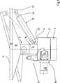
Die erfindungsgemäße Nachführeinrichtung für eine auf ein sich bewegendes Objekt auszurichtende Einheit, insbesondere einen Sonnenkollektor, hat eine die Einheit tragenden Konsole, die auf einer mittels eines hydraulischen Azimutantriebs um eine Azimutachse drehbaren Welle aufgenommen ist. Weiterhin hat die Nachführeinrichtung eine hydraulisch verstellbare Neigeeinrichtung zur Neigung der Konsole, wobei eine Lagerung der Welle sowie der Azimutantrieb an oder in einem Gehäuse angeordnet sind. Dabei sind zumindest ein Abschnitt der Welle mit ihrer Lagerung und ein Druckmitteltank mit Druckmittel zur Versorgung des Azimutantriebs und der Neigeeinrichtung gemeinsam in einem Hohlraum des Gehäuses angeordnet. Da das Druckmittel (Hydrauliköl) die Lagerung schmiert, sind der vorrichtungstechnische und der wartungstechnische Aufwand der erfindungsgemäßen Nachführeinrichtung verringert.The tracking device according to the invention for a unit to be aligned with a moving object, in particular a solar collector, has a console supporting the unit, which is received on a shaft rotatable about an azimuth axis by means of a hydraulic azimuth drive. Furthermore, the tracking device has a hydraulically adjustable tilting device for tilting the console, wherein a bearing of the shaft and the azimuth drive are arranged on or in a housing. In this case, at least a portion of the shaft with its storage and a pressure medium tank with pressure means for supplying the azimuth drive and the tilting device are arranged together in a cavity of the housing. Since the pressure medium (hydraulic oil) lubricates the storage, the device-technical and the maintenance-technical effort of the tracking device according to the invention are reduced.
Weitere vorteilhafte Ausgestaltungen der Erfindung sind in den abhängigen Patentansprüchen beschrieben.Further advantageous embodiments of the invention are described in the dependent claims.
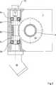
Bei einer bevorzugten Weiterbildung hat der Azimutantrieb einen im Gehäuse angeordneten Schneckentrieb, dessen Schnecke mit einem an der Welle angeordneten Schneckenrad kämmt, wobei die Schnecke mittels eines Hydromotors angetrieben ist. Da das Druckmittel (Hydrauliköl) den Schneckentrieb schmiert, sind der vorrichtungstechnische und der wartungstechnische Aufwand weiter verringert.In a preferred development, the azimuth drive has a worm gear arranged in the housing, the worm of which meshes with a worm wheel arranged on the shaft, the worm being driven by means of a hydraulic motor. Since the pressure medium (hydraulic oil) lubricates the worm drive, the device-technical and the maintenance-technical effort are further reduced.
Bei einer bevorzugten Weiterbildung ist der Hydromotor ein an einer Außenwand des Gehäuses befestigter Axialkolbenmotor, dessen hydraulische Anschlüsse an einer dem Gehäuse zugewandten Stirnseite angeordnet sind.In a preferred embodiment, the hydraulic motor is a fixed to an outer wall of the housing axial piston motor, the hydraulic connections are arranged on a housing facing the end face.
Dabei kann die Schnecke an einer Schneckenachse ausgebildet sein, die beidseitig am Gehäuse zugänglich ist, und an deren ersten Endabschnitt der Hydromotor und an dessen zweiten Endabschnitt ein Drehzahlsensor angeordnet ist. Letzterer ist vorzugsweise ein Potentiometer, mit dem kostengünstig eine hohe Auflösung und eine absolute Winkelangabe erzielt werden können.In this case, the screw may be formed on a screw axis, which is accessible on both sides of the housing, and at the first end portion of the hydraulic motor and at the second end portion of a speed sensor is arranged. The latter is preferably a potentiometer, with the cost of a high resolution and an absolute angle can be achieved.
Bei einer besonders bevorzugten Weiterbildung hat die Neigeeinrichtung einen an der Konsole angreifenden und an der Welle mittelbar oder unmittelbar angreifenden Hydraulikzylinder, der über eine am Gehäuse angeordnete Hydropumpe mit Druckmittel versorgt werden kann.In a particularly preferred embodiment, the tilting device has an attacking on the console and the shaft directly or indirectly attacking hydraulic cylinder, which can be supplied via a arranged on the housing hydraulic pump with pressure medium.
Aus Gründen eines kompakten Aufbaus der erfindungsgemäßen Nachführeinrichtung erfolgt neben der Neigeeinrichtung vorzugsweise auch die Versorgung des Azimutantriebes über die Hydropumpe und einen Elektromotor, der die Hydropumpe antreibt.For reasons of a compact construction of the tracking device according to the invention, in addition to the tilting device preferably also the supply of the azimuth drive via the hydraulic pump and an electric motor which drives the hydraulic pump.
Dabei kann der Elektromotor ein robuster Synchronmotor und die Hydropumpe eine Zahnradpumpe sein, die beide mit Bezug zur Welle in Radialrichtung an das Gehäuse angesetzt sind.In this case, the electric motor may be a robust synchronous motor and the hydraulic pump may be a gear pump, both of which are attached with respect to the shaft in the radial direction of the housing.
Um Verrohrungen zu verkürzen oder ganz einzusparen, können ein Tankanschluss und ein Druckanschluss an einer dem Gehäuse zugewandten Seite der Zahnradpumpe angeordnet sein.In order to shorten or completely save piping, a tank connection and a pressure connection can be arranged on a side of the gear pump facing the housing.
Wenn ein seitlicher Wandabschnitt des Gehäuses gleichzeitig eine Wand der Zahnradpumpe bildet, kann eine stirnseitige Wand der Zahnradpumpe entfallen. Wenn dabei der Tankanschluss und der Druckanschluss Durchgangsbohrungen des Wandabschnitts sind, ist diesbezüglich keine Verrohrung nötig.If a side wall portion of the housing simultaneously forms a wall of the gear pump, a front wall of the gear pump can be omitted. If the tank connection and the pressure connection are through-holes of the wall section, no piping is necessary in this case.
Eine bevorzugte Weiterbildung hat einen Steuerblock mit einer elektronischen Steuereinheit und/oder Ventilen zur Steuerung der Versorgung des Azimutantriebs und der Neigeeinrichtung.A preferred development has a control block with an electronic control unit and / or valves for controlling the supply of the azimuth drive and the tilting device.
Die Montage der Konsole auf der Welle ist vereinfacht, wenn die Welle einen Abschnitt hat, der (zur Konsole hin) aus dem Gehäuse auskragt.The mounting of the console on the shaft is simplified when the shaft has a portion that protrudes (towards the console) out of the housing.
Der Steuerblock kann benachbart zum auskragenden Abschnitt der Welle an einer der Konsole zugewandten Oberseite des Gehäuses oder seitlich am Gehäuse oder im Gehäuse angeordnet sein. Letztere Integration bietet besonderen Schutz vor äußeren Einwirkungen. The control block may be disposed adjacent to the cantilevered portion of the shaft at a console facing top of the housing or laterally on the housing or in the housing. The latter integration offers special protection against external influences.
Um das Druckmittel im Hohlraum des Gehäuses vor Verschmutzung zu schützen wird es bevorzugt, wenn am Gehäuse eine Schmutzdichtung angebracht ist, die an der Welle anliegt.In order to protect the pressure medium in the cavity of the housing from contamination, it is preferred if a dirt seal is attached to the housing, which bears against the shaft.
Um den Hohlraum bzw. das Tankvolumen zu maximieren kann zumindest der im Gehäuse aufgenommene Abschnitt der Welle hohl ausgeführt sein.In order to maximize the cavity or the tank volume, at least the portion of the shaft accommodated in the housing can be made hollow.
Bevorzugt wird eine Lagerung der Welle mit einem Axiallager zur Abstützung der Gewichtskraft der Konsole und der Einheit und mit einem Radiallager, wobei das Axiallager zwischen dem Radiallager und der Konsole angeordnet ist. Beide Lager sind erfindungsgemäß zur Reibungsminimierung in das Druckmittel eingetaucht.Preference is given to a bearing of the shaft with a thrust bearing for supporting the weight of the console and the unit and with a radial bearing, wherein the thrust bearing between the radial bearing and the console is arranged. Both bearings are immersed according to the invention for minimizing friction in the pressure medium.
Aus Gründen einer einfachen Fertigung und Montage kann das Gehäuse ein Gussteil sein, durch dessen Oberseite die Welle einsetzbar ist, und an dessen von der Konsole abgewandten Unterseite eine Öffnung angeordnet ist, durch die das Axiallager und das Radiallager einsetzbar sind. Die Öffnung an der Unterseite ist von einem Gehäusedeckel verschließbar. Ein derartiges Gussteil kann vor der Montage spanend bearbeitet, werden, insbesondere für die beiden Lagersitze, für die Schmutzdichtung und für den Anlagebereich des Gehäusedeckels.For reasons of ease of manufacture and assembly, the housing may be a casting, through the upper side of which the shaft can be inserted, and at the side remote from the console underside an opening is arranged, through which the thrust bearing and the radial bearing can be used. The opening at the bottom can be closed by a housing cover. Such a casting can be machined prior to assembly, in particular for the two bearing seats, for the dirt seal and for the contact area of the housing cover.
Bei einer Weiterbildung trägt die Welle ein Schwenklager der Konsole, wobei die Achse des Schwenklagers in einer Radialebene der Welle liegt.In a further development, the shaft carries a pivot bearing of the console, wherein the axis of the pivot bearing is located in a radial plane of the shaft.
Im Folgenden wird anhand der Figuren ein Ausführungsbeispiel der Erfindung detailliert beschrieben. Es zeigen:In the following, an embodiment of the invention will be described in detail with reference to FIGS. Show it:
Der vertikalen Bewegungsrichtung der Sonne kann die Nachführeinrichtung dadurch folgen, dass das Solar-Panel
Die Drehung der Welle
Beide hydraulische Aktoren
Im Innern des Gehäuses
In eine umlaufende Ausnehmung an der Oberseite
Der Hydromotor
Offenbart ist eine Nachführeinrichtung für eine auf ein sich bewegendes Objekt auszurichtende Einheit, insbesondere einen Sonnenkollektor, die eine die Einheit tragenden Konsole hat, die auf einer mittels eines hydraulischen Azimutantriebs um eine Azimutachse drehbaren Welle aufgenommen ist. Weiterhin hat die Nachführeinrichtung eine hydraulisch verstellbare Neigeeinrichtung zur Neigung der Konsole, wobei eine Lagerung der Welle sowie der Azimutantrieb an oder in einem Gehäuse angeordnet sind. Dabei sind zumindest ein Abschnitt der Welle mit ihrer Lagerung, der Azimutantrieb und ein Druckmitteltank mit Druckmittel zur Versorgung des Azimutantriebs und der Neigeeinrichtung in einem gemeinsamen Hohlraum des Gehäuses angeordnet.Disclosed is a tracking device for a unit to be aligned with a moving object, in particular a solar collector, which has a console supporting the unit, which is accommodated on a shaft rotatable about an azimuth axis by means of a hydraulic azimuth drive. Furthermore, the tracking device has a hydraulically adjustable tilting device for tilting the console, wherein a bearing of the shaft and the azimuth drive are arranged on or in a housing. In this case, at least a portion of the shaft with its storage, the azimuth drive and a pressure medium tank with pressure medium for supplying the azimuth drive and the tilting device are arranged in a common cavity of the housing.
BezugszeichenlisteLIST OF REFERENCE NUMBERS
- 11
- Mastmast
- 22
- Gehäusecasing
- 44
- Oberseitetop
- 66
- Wellewave
- 88th
- Schwenklagerpivot bearing
- 1010
- Konsoleconsole
- 1212
- Solar-PanelSolar Panel
- 1414
- Oberseitetop
- 1616
- Azimutachseazimuth axis
- 1818
- Hydrozylinderhydraulic cylinders
- 20, 2220, 22
- Gelenkjoint
- 2424
- Kolbenstangepiston rod
- 2626
- Hydromotorhydraulic motor
- 2828
- Synchronmotorsynchronous motor
- 3030
- Zahnradpumpegear pump
- 3232
- Steuerblockcontrol block
- 3434
- Umfangsabschnittperipheral portion
- 3636
- Axiallagerthrust
- 3838
- Radiallagerradial bearings
- 4040
- Stufestep
- 4242
- Hülseshell
- 4444
- Gehäusedeckelhousing cover
- 46, 4846, 48
- Zahnradradgear wheel
- 4949
- Tankanschlusstank connection
- 5050
- Schneckeslug
- 5151
- Druckanschlusspressure connection
- 5252
- Schneckenradworm
- 5353
- Schmutzdichtungdirt seal
- 5454
- Schneckenachsescrew axis
- 56, 5856, 58
- Wälzlagerroller bearing
- 6060
- Durchgangsausnehmungthrough recess
- 6262
- Potentiometerpotentiometer
- TT
- Tanktank
ZITATE ENTHALTEN IN DER BESCHREIBUNG QUOTES INCLUDE IN THE DESCRIPTION
Diese Liste der vom Anmelder aufgeführten Dokumente wurde automatisiert erzeugt und ist ausschließlich zur besseren Information des Lesers aufgenommen. Die Liste ist nicht Bestandteil der deutschen Patent- bzw. Gebrauchsmusteranmeldung. Das DPMA übernimmt keinerlei Haftung für etwaige Fehler oder Auslassungen.This list of the documents listed by the applicant has been generated automatically and is included solely for the better information of the reader. The list is not part of the German patent or utility model application. The DPMA assumes no liability for any errors or omissions.
Zitierte PatentliteraturCited patent literature
- DE 10022236 B4[0002]DE 10022236 B4[0002]
Claims (17)
Translated fromGermanPriority Applications (4)
| Application Number | Priority Date | Filing Date | Title |
|---|---|---|---|
| DE102009039341ADE102009039341A1 (en) | 2009-08-29 | 2009-08-29 | tracking device |
| US13/393,217US20120279489A1 (en) | 2009-08-29 | 2010-07-27 | Tracking Device |
| PCT/EP2010/004579WO2011023274A1 (en) | 2009-08-29 | 2010-07-27 | Tracking device |
| EP10742726.2AEP2470839B1 (en) | 2009-08-29 | 2010-07-27 | Tracking device |
Applications Claiming Priority (1)
| Application Number | Priority Date | Filing Date | Title |
|---|---|---|---|
| DE102009039341ADE102009039341A1 (en) | 2009-08-29 | 2009-08-29 | tracking device |
Publications (1)
| Publication Number | Publication Date |
|---|---|
| DE102009039341A1true DE102009039341A1 (en) | 2011-03-03 |
Family
ID=43242158
Family Applications (1)
| Application Number | Title | Priority Date | Filing Date |
|---|---|---|---|
| DE102009039341AWithdrawnDE102009039341A1 (en) | 2009-08-29 | 2009-08-29 | tracking device |
Country Status (4)
| Country | Link |
|---|---|
| US (1) | US20120279489A1 (en) |
| EP (1) | EP2470839B1 (en) |
| DE (1) | DE102009039341A1 (en) |
| WO (1) | WO2011023274A1 (en) |
Families Citing this family (8)
| Publication number | Priority date | Publication date | Assignee | Title |
|---|---|---|---|---|
| DE102010042123B3 (en)* | 2010-10-07 | 2012-03-22 | Siemens Aktiengesellschaft | Rotary encoders arrangement for use in handling- and automation engineering field, has X-ray detector driven by rotating device, and rotary encoders coupled with torsion spring over connection unit to determine rotation of detector |
| CN102645035B (en)* | 2012-05-04 | 2013-11-06 | 中国科学院电工研究所 | Hydraulic drive mechanism of heliostat |
| US9766319B2 (en) | 2012-12-10 | 2017-09-19 | Nextracker Inc. | Off-set drive assembly for solar tracker |
| US10008975B2 (en) | 2012-12-10 | 2018-06-26 | Nextracker Inc. | Clamp assembly for solar tracker |
| US9466749B1 (en)* | 2012-12-10 | 2016-10-11 | Nextracker Inc. | Balanced solar tracker clamp |
| JP2016504901A (en) | 2012-12-10 | 2016-02-12 | ネクストラッカー インコーポレイテッドNEXTracker Inc. | Horizontal balance solar tracking device |
| US9322437B2 (en) | 2012-12-28 | 2016-04-26 | Sunpower Corporation | Support for solar energy collection |
| JP6263209B2 (en)* | 2016-02-22 | 2018-01-17 | 株式会社ジェンク | Variable angle solar power generation system |
Citations (1)
| Publication number | Priority date | Publication date | Assignee | Title |
|---|---|---|---|---|
| DE10022236B4 (en) | 2000-05-08 | 2005-09-01 | Grollius, Horst-Walter, Dr.-Ing. | Mechanical / hydraulic adjustment system for biaxial solar generators tracking the position of the sun |
Family Cites Families (4)
| Publication number | Priority date | Publication date | Assignee | Title |
|---|---|---|---|---|
| US6123067A (en)* | 1999-03-31 | 2000-09-26 | Amonix, Inc. | Solar collector tracking system |
| US7509701B2 (en)* | 2001-07-25 | 2009-03-31 | Bosch Rexroth Ag | Lifting system |
| US8176806B2 (en)* | 2006-05-24 | 2012-05-15 | Siemens Aktiengesellschaft | Two-axle drive system |
| DE202007008593U1 (en)* | 2007-06-15 | 2007-08-23 | Lehle Gmbh | Device, in particular heliostat or photovoltaic device |
- 2009
- 2009-08-29DEDE102009039341Apatent/DE102009039341A1/ennot_activeWithdrawn
- 2010
- 2010-07-27WOPCT/EP2010/004579patent/WO2011023274A1/enactiveApplication Filing
- 2010-07-27USUS13/393,217patent/US20120279489A1/ennot_activeAbandoned
- 2010-07-27EPEP10742726.2Apatent/EP2470839B1/ennot_activeNot-in-force
Patent Citations (1)
| Publication number | Priority date | Publication date | Assignee | Title |
|---|---|---|---|---|
| DE10022236B4 (en) | 2000-05-08 | 2005-09-01 | Grollius, Horst-Walter, Dr.-Ing. | Mechanical / hydraulic adjustment system for biaxial solar generators tracking the position of the sun |
Also Published As
| Publication number | Publication date |
|---|---|
| WO2011023274A1 (en) | 2011-03-03 |
| EP2470839B1 (en) | 2013-10-09 |
| EP2470839A1 (en) | 2012-07-04 |
| US20120279489A1 (en) | 2012-11-08 |
Similar Documents
| Publication | Publication Date | Title |
|---|---|---|
| EP2470839B1 (en) | Tracking device | |
| EP2552748B1 (en) | Camera arrangement for a vehicle | |
| DE69923553T2 (en) | Drive device with a liquid-cooled electric motor and planetary gear | |
| EP2403751B1 (en) | Modular gondola drive for a floating device | |
| EP2323771B2 (en) | Heavy-duty drive arrangement and mill driven by the same | |
| EP2398699B1 (en) | Ship drive comprising a drive unit that can be pivoted under water | |
| EP2795115B1 (en) | Blade bearing or nacelle bearing of a wind turbine | |
| DE202009017658U1 (en) | Device, in particular heliostat or photovoltaic device | |
| DE10022236B4 (en) | Mechanical / hydraulic adjustment system for biaxial solar generators tracking the position of the sun | |
| DE102011011164A1 (en) | Rotor bearing for electrical machine | |
| EP2151659B1 (en) | Gun station | |
| DE19927454B4 (en) | Pump unit for ABS / ASR / VSC brake system | |
| EP2729361B1 (en) | Actuator device | |
| DE10320456B4 (en) | swing motor | |
| EP2984368B1 (en) | Torque bearing, wind turbine, and vehicle | |
| DE102015105543A1 (en) | transmission cooling | |
| EP2675046A2 (en) | Adjustment device | |
| EP2228538B1 (en) | Multi-layer circulation pump aggregate | |
| EP2503195B1 (en) | Scavenging pressure limiting valve in an hydrostatic transmission | |
| DE102011015234A1 (en) | Hydromechanical transmission | |
| DE102012004073A1 (en) | Hydromechanical drive for use in drive train of agricultural vehicle i.e. tractor, has hydrostatic transmission comprising supporting frame with recess that is opened transverse to shaft, where one of shafts extends through recess | |
| DE102012017325B4 (en) | turbocharger | |
| DE102008030747A1 (en) | Tracking device for e.g. solar collector, has housing arranged on base and rotatably mounted around longitudinal axis of drive shaft, where common drive is assigned to support shaft and drive shaft | |
| DE3046209C2 (en) | ||
| EP1116849A2 (en) | Driving assembly for swingable parts on vehicles |
Legal Events
| Date | Code | Title | Description |
|---|---|---|---|
| R119 | Application deemed withdrawn, or ip right lapsed, due to non-payment of renewal fee | ||
| R119 | Application deemed withdrawn, or ip right lapsed, due to non-payment of renewal fee | Effective date:20150303 |