DE102009037336B4 - Antenna characterization in a waveguide - Google Patents
Antenna characterization in a waveguideDownload PDFInfo
- Publication number
- DE102009037336B4 DE102009037336B4DE102009037336.5ADE102009037336ADE102009037336B4DE 102009037336 B4DE102009037336 B4DE 102009037336B4DE 102009037336 ADE102009037336 ADE 102009037336ADE 102009037336 B4DE102009037336 B4DE 102009037336B4
- Authority
- DE
- Germany
- Prior art keywords
- antenna
- waveguide
- characteristic
- response signal
- signal
- Prior art date
- Legal status (The legal status is an assumption and is not a legal conclusion. Google has not performed a legal analysis and makes no representation as to the accuracy of the status listed.)
- Active
Links
Images

Classifications
- G—PHYSICS
- G01—MEASURING; TESTING
- G01R—MEASURING ELECTRIC VARIABLES; MEASURING MAGNETIC VARIABLES
- G01R29/00—Arrangements for measuring or indicating electric quantities not covered by groups G01R19/00 - G01R27/00
- G01R29/08—Measuring electromagnetic field characteristics
- G01R29/0807—Measuring electromagnetic field characteristics characterised by the application
- G01R29/0814—Field measurements related to measuring influence on or from apparatus, components or humans, e.g. in ESD, EMI, EMC, EMP testing, measuring radiation leakage; detecting presence of micro- or radiowave emitters; dosimetry; testing shielding; measurements related to lightning
- G01R29/0821—Field measurements related to measuring influence on or from apparatus, components or humans, e.g. in ESD, EMI, EMC, EMP testing, measuring radiation leakage; detecting presence of micro- or radiowave emitters; dosimetry; testing shielding; measurements related to lightning rooms and test sites therefor, e.g. anechoic chambers, open field sites or TEM cells
- G01R29/0828—TEM-cells
- G—PHYSICS
- G01—MEASURING; TESTING
- G01R—MEASURING ELECTRIC VARIABLES; MEASURING MAGNETIC VARIABLES
- G01R29/00—Arrangements for measuring or indicating electric quantities not covered by groups G01R19/00 - G01R27/00
- G01R29/08—Measuring electromagnetic field characteristics
- G01R29/10—Radiation diagrams of antennas
- G01R29/105—Radiation diagrams of antennas using anechoic chambers; Chambers or open field sites used therefor
- H—ELECTRICITY
- H01—ELECTRIC ELEMENTS
- H01Q—ANTENNAS, i.e. RADIO AERIALS
- H01Q17/00—Devices for absorbing waves radiated from an antenna; Combinations of such devices with active antenna elements or systems
Landscapes
- Physics & Mathematics (AREA)
- Electromagnetism (AREA)
- General Physics & Mathematics (AREA)
- Variable-Direction Aerials And Aerial Arrays (AREA)
- Measurement Of Resistance Or Impedance (AREA)
Abstract
Translated fromGermanDescription
Translated fromGermanDie Erfindung betrifft ein Verfahren zur Bestimmung wenigstens eines Charakteristikums einer Antenne gemäß dem Patentanspruch 1 und eine Messeinrichtung nach dem Patentanspruch 14.The invention relates to a method for determining at least one characteristic of an antenna according to
Unter einem Charakteristikum einer Antenne wird jede Art von Kenngröße der Antenne verstanden, wie z.B. einzelne Kennwerte, Zeitverläufe von Kennwerten oder richtungs- und frequenzabhängige Kenngrößen wie z.B. Abstrahlungsdiagramme. Die Bestimmung solcher charakteristischen Daten von Antennen erfolgt bei bekannten Methoden üblicherweise im Frequenzbereich. Dabei wird von einem Frequenzgenerator ein Prüfsignal erzeugt, derart, dass über einen bestimmten, zu untersuchenden Frequenzbereich ein so genannter Frequenz-Sweep durchfahren wird. Jede Frequenz wird dabei für einen kurzen Zeitraum konstant gehalten, bis an der Antenne ein eingeschwungener Zustand eintritt. Sodann erfolgt eine Messung an der Antenne zur Ermittlung der charakteristischen Daten.An antenna characteristic is understood to be any type of characteristic of the antenna, such as individual characteristic values, time courses of characteristic values or direction and frequency-dependent characteristics such as radiation patterns. The determination of such characteristic data of antennas is usually carried out in the frequency range using known methods. A frequency generator generates a test signal in such a way that a so-called frequency sweep is carried out over a specific frequency range to be examined. Each frequency is kept constant for a short period of time until the antenna reaches a steady state. A measurement is then carried out on the antenna to determine the characteristic data.
Ein bekanntes Verfahren ist z.B. die Referenz-Antennen-Methode, die eine absolut definiert abstrahlende Antenne, z.B. eine offene Hohlleitersonde bzw. eine Hornantenne, als Referenz benötigt. Ein Nachteil dieses Verfahren besteht darin, dass der erforderliche apparative Messaufwand zeitlich und/oder kostenmäßig relativ hoch ist, da oftmals eine Vielzahl von Referenzantennen bereitgestellt und sequentiell vermessen werden müssen, da solche Referenzantennen eine begrenzte, relativ schmalbandige Nutzbandbreite aufweisen. Um zudem eine hohe Polarisationsreinheit bereitzustellen, sind präzise gefertigte und absolut charakterisierte Referenzantennen notwendig und daher relativ teuer. Die Anschaffung rechnet sich daher in vielen Fällen nicht. Bekannt ist zudem die 2-Antennen-Methode, bei der sich zwei exakt baugleiche Antennen in einem definierten Abstand in einem reflexionsfreien Raum gegenüberstehen müssen. Diese Methode birgt das Problem in sich, die zwei exakt baugleichen Antennen zu beschaffen, was im Einzelfall schwierig sein kann. Weiterhin ist die 3-Antennen-Methode bekannt, die zwar gute Ergebnisse erbringt, jedoch relativ zeit- und arbeitsintensiv ist.One well-known method is the reference antenna method, which requires an absolutely defined radiating antenna, e.g. an open waveguide probe or a horn antenna, as a reference. A disadvantage of this method is that the required equipment is relatively expensive in terms of time and/or cost, since a large number of reference antennas often have to be provided and measured sequentially, since such reference antennas have a limited, relatively narrow usable bandwidth. In order to provide a high level of polarization purity, precisely manufactured and absolutely characterized reference antennas are necessary and therefore relatively expensive. In many cases, purchasing them is therefore not worthwhile. Another well-known method is the 2-antenna method, in which two exactly identical antennas have to face each other at a defined distance in a reflection-free room. This method involves the problem of obtaining the two exactly identical antennas, which can be difficult in individual cases. The 3-antenna method is also known, which produces good results but is relatively time- and labor-intensive.
Aus der Veröffentlichung
Aus der
Aus der
Aus der Veröffentlichung
Die Veröffentlichung
Die Veröffentlichung
Der Erfindung liegt daher die Aufgabe zugrunde, ein rationelleres Verfahren zur Bestimmung wenigstens eines Charakteristikums einer Antenne anzugeben.The invention is therefore based on the object of specifying a more rational method for determining at least one characteristic of an antenna.
Diese Aufgabe wird durch die in den nebengeordneten Ansprüchen angegebene Erfindung gelöst. Die Unteransprüche geben vorteilhafte Weiterbildungen der Erfindung an.This object is achieved by the invention specified in the independent claims. The subclaims specify advantageous developments of the invention.
Die Erfindung kann vorteilhaft mit einfachen Mitteln realisiert werden. Es ist vorteilhaft, dass auf weit verbreitete Messgeräte zurückgegriffen werden kann, wie z.B. einen Wellenleiter. Als geeignete Wellenleiter für eine Anwendung der Erfindung kommen grundsätzlich alle Arten von Wellenleitern in Frage, die ausreichenden Raum zur Platzierung der Antenne bieten und zumindest zeitweise am Ort der Antenne ein TEM-Feld bereitstellen. Als TEM-Feld bezeichnet man ein transversales elektromagnetisches Feld, bei dem der Feldvektor des elektrischen Felds und der Feldvektor des magnetischen Felds senkrecht aufeinander stehen und beide Feldvektoren senkrecht zur Ausbreitungsrichtung stehen.The invention can be advantageously implemented using simple means. It is advantageous that widely used measuring devices can be used, such as a waveguide. In principle, all types of waveguides that offer sufficient space for positioning the antenna and that provide a TEM field at least temporarily at the location of the antenna can be considered as suitable waveguides for an application of the invention. A TEM field is a transverse electromagnetic field in which the field vector of the electric field and the field vector of the magnetic field are perpendicular to each other and both field vectors are perpendicular to the direction of propagation.
Dementsprechend kommen als für die Anwendung des erfindungsgemäßen Verfahrens vorteilhaft anwendbare Wellenleiter diverse Anordnungen in Frage, z.B. eine Parallelplattenleitung, bestehend aus einem oberen und einem unteren Metallblech, die einen bestimmten Raum beinhalten, in dem die zu vermessende Antenne platziert werden kann. Der von dem Wellenleiter umgebene Raum muss für die Ausführung des erfindungsgemäßen Verfahrens nicht zwangsläufig ein geschlossener Raum sein, denkbar ist auch ein seitlich teilweise geöffneter Raum, wobei eine Abschirmung gegenüber äußeren Störeinflüssen dann geringer ist als bei einem geschlossenen Wellenleiter, wie z.B. einen Hohlleiter mit gleichbleibendem oder sich in Längsrichtung aufweitendem Koaxialwellenleiter.Accordingly, various arrangements can be considered as waveguides that can be used advantageously for the application of the method according to the invention, e.g. a parallel plate line consisting of an upper and a lower metal sheet, which contain a certain space in which the antenna to be measured can be placed. The space surrounded by the waveguide does not necessarily have to be a closed space for the implementation of the method according to the invention; a space that is partially open at the sides is also conceivable, in which case the shielding against external interference is less than with a closed waveguide, such as a waveguide with a constant or longitudinally widening coaxial waveguide.
Für eine Anwendung der Erfindung ist insbesondere ein TEM-Wellenleiter vorteilhaft, da dieser eine Ausbreitung des für das erfindungsgemäße Verfahren vorteilhaften TEM-Felds am Ort der Antenne begünstigt. Insbesondere ist die Verwendung einer TEM-Zelle vorteilhaft, d.h. eine Zelle, die beispielsweise im Bereich von EMV-Untersuchungen (EMV = elektromagnetische Verträglichkeit) weit verbreitete Anwendung findet. Als TEM-Zelle kommt z.B. eine Crawford-Zelle in Frage. Besonders vorteilhaft kann auch eine GTEM-Zelle (GTEM = Gigahertz Transversal Elektromagnetisch) aufgrund ihres erweiterten Nutzfrequenzbereichs verwendet werden. Hierbei handelt es sich um eine geschlossene und metallisch geschirmte Messeinrichtung in Form eines sich aufweitenden Koaxialwellenleiters. Auch GTEM-Zellen sind in verschiedenen Baugrößen bereits weit verbreitet, z.B. für EMV-Untersuchungen und daher für eine Anwendung der Erfindung einfach verfügbar.A TEM waveguide is particularly advantageous for an application of the invention, since it promotes the propagation of the TEM field, which is advantageous for the method according to the invention, at the location of the antenna. The use of a TEM cell is particularly advantageous, i.e. a cell that is widely used, for example, in the field of EMC tests (EMC = electromagnetic compatibility). A Crawford cell, for example, can be used as a TEM cell. A GTEM cell (GTEM = Gigahertz Transverse Electromagnetic) can also be used particularly advantageously due to its extended useful frequency range. This is a closed and metallically shielded measuring device in the form of an expanding coaxial waveguide. GTEM cells are also already widely used in various sizes, e.g. for EMC tests, and are therefore easily available for an application of the invention.
Mit der vorliegenden Erfindung wird der Einsatzbereich von TEM-Zellen, insbesondere von GTEM-Zellen, um die Möglichkeit zur Charakterisierung von Antennen erweitert. Die Erfindung schlägt gegenüber den bekannten, im Stand der Technik beschriebenen Wegen nunmehr einen vollständig anderen Ansatz vor. Gemäß der Erfindung wird ein elektrisches Anregungssignal in einen Einspeiseanschluss des Wellenleiters eingespeist. Ein in Folge des Anregungssignals von der Antenne abgegebenes elektrisches Antwortsignal wird aufgenommen, z.B. mit einem Oszilloskop oder einem Signalanalysator wie beispielsweise einem Spektrum- oder Netzwerkanalysator (NWA). Das Anregungssignal kann grundsätzlich beliebiger Art sein, z.B. ein einzelner Anregungspuls, eine Mehrzahl von Anregungspulsen oder eine Abfolge von Frequenzen, wie bei dem eingangs erwähnten Frequenz-Sweep. Gemäß der Erfindung wird für die Bestimmung des wenigstens einen Charakteristikums der Antenne wenigstens ein Anteil des Antwortsignals und ein korrespondierender Anteil des Anregungssignals verwendet. Hierbei wird ein bestimmter Anteil des Antwortsignals verwendet, nämlich ein im Zeitbereich ausgewerteter Zeitabschnitt, der folgende Bedingungen erfüllt:
- i) am Ort der Antenne existieren nur eine oder mehrere von dem Anregungssignal bewirkte, von dem Einspeiseanschluss in Richtung Antenne laufende Wellen des elektromagnetischen Felds (nachfolgend auch als hinlaufende Wellen bezeichnet),
- ii) das elektromagnetische Feld ist am Ort der Antenne ein TEM-Feld.
- i) at the location of the antenna there are only one or more of the excitation signal-induced electromagnetic field waves traveling from the feed connection towards the antenna (hereinafter also referred to as forward waves),
- ii) the electromagnetic field at the location of the antenna is a TEM field.
Das TEM-Feld kann sich auf ebenen und/oder sphärisch gekrümmten Phasenfronten ausbreiten.The TEM field can propagate on flat and/or spherically curved phase fronts.
Durch die zuvor genannte Bedingung i) wird sichergestellt, dass der ausgewertete Anteil des Antwortsignals keine verfälschenden Überlagerungen durch rücklaufende Wellen, z.B. durch Reflexionen an der Rückwand der GTEM-Zelle, enthält. Stattdessen wird ein solcher Zeitabschnitt verwendet, bei dem am Ort der Antenne nur hinlaufende Wellen des elektromagnetischen Felds existieren. Hierdurch kann eine hohe Messgenauigkeit und Reproduzierbarkeit der Antennencharakterisierung erreicht werden.The aforementioned condition i) ensures that the evaluated portion of the response signal does not contain any distorting superpositions caused by returning waves, e.g. by reflections on the rear wall of the GTEM cell. Instead, a time period is used in which only forward waves of the electromagnetic field exist at the location of the antenna. This enables a high level of measurement accuracy and reproducibility of the antenna characterization to be achieved.
Gemäß der Bedingung ii) ist zudem vorgesehen, dass ein Zeitabschnitt verwendet wird, in dem das elektromagnetische Feld am Ort der Antenne ein TEM-Feld ist. Durch die Festlegung des Zeitabschnitts können somit Messverfälschungen, die durch zeitweise Abweichungen des Felds von der TEM-Charakteristik auftreten, aus dem Messergebnis eliminiert werden und somit eine Verfälschung des Messergebnisses vermieden werden. Das Vorliegen einer TEM-Charakteristik des Felds hat den Vorteil, dass die Messung äquivalente Feldbedingungen schafft, die denen herkömmlicher Referenzantennen-Messungen, bei denen sich die zu untersuchende Antenne für gewöhnlich im Fernfeld einer Referenzantenne befindet, entspricht. Dieses Referenzantennen-Fernfeld ist am Ort der zu untersuchenden Antenne ist ein leicht sphärisch gekrümmtes TEM-Feld und daher weitgehend identisch zu den nahezu ebenen Bedingungen einer Freifeld-Messung. Die Phasenfronten des TEM-Feldes innerhalb einer GTEM-Zelle sind ebenfalls aufgrund des Septumssteigungswinkels leicht sphärisch gekrümmt.According to condition ii), it is also intended that a time period is used in which the electromagnetic field at the location of the antenna is a TEM field. By specifying the time period, measurement distortions that occur due to temporary deviations of the field from the TEM characteristic can be eliminated from the measurement result and thus falsification of the measurement result can be avoided. The presence of a TEM characteristic of the field has the advantage that the measurement creates equivalent field conditions that correspond to those of conventional reference antenna measurements, in which the antenna to be examined is usually located in the far field of a reference antenna. This reference antenna far field is a slightly spherically curved TEM field at the location of the antenna to be examined and is therefore largely identical to the almost flat conditions of a free field measurement. The phase fronts of the TEM field within a GTEM cell are also slightly spherically curved due to the septum pitch angle.
Die Verwendung einer GTEM-Zelle hat aufgrund ihrer speziellen Charakteristika den Vorteil, dass die Auswertung der Messergebnisse vereinfacht wird. Eine GTEM-Zelle hat eine Dirac-Funktion als ersten Anteil der Impulsantwort (vgl. IEEE-Veröffentlichung „Pulse Propagation in Gigahertz Transverse Electromagnetic Cells“, Thye, Armbrecht, Koch). Daher verfälscht die GTEM-Zelle aufgrund ihrer eigenen Charakteristika das Antwortsignal der Antenne nicht. Insbesondere ist nicht der Einfluss einer Faltung der GTEM-Charakteristika mit dem Antwortsignal zu berücksichtigen. Die Transformation des Antwortsignals in das Signal am Ort der Antenne erfolgt somit verzerrungsfrei (dispersionsfrei).The use of a GTEM cell has the advantage of simplifying the evaluation of the measurement results due to its special characteristics. A GTEM cell has a Dirac function as the first part of the impulse response (see IEEE publication "Pulse Propagation in Gigahertz Transverse Electromagnetic Cells", Thye, Armbrecht, Koch). Therefore, due to its own characteristics, the GTEM cell does not distort the antenna's response signal. In particular, the influence of a convolution of the GTEM characteristics with the response signal does not need to be taken into account. The transformation of the response signal into the signal at the antenna location is therefore distortion-free (dispersion-free).
Es wurden in der Vergangenheit bereits Überlegungen und Untersuchungen angestellt, GTEM-Zellen für Antennenmessungen zu verwenden. Hierbei konnte jedoch keine ausreichend exakte Korrelation zwischen den Messergebnissen mit einer GTEM-Zelle und den Messergebnissen im Freifeld hergestellt werden. Dies war zum einen darin begründet, dass die untersuchte Antenne als Sendeantenne verwendet wurde, was zu einer Anregung und damit zu parasitären Resonanzen aufgrund höherer Feldmoden in der GTEM-Zelle führte, die auf undefinierte Weise in eine Spannung am Koaxialanschluss der GTEM-Zelle transformiert wurde. Zum anderen konnte im Empfangsfall ebenfalls aufgrund dieser Multimode-ResonanzErscheinungen, die begünstigt durch nicht ideale Absorptionseigenschaften des an der Rückwand der GTEM-Zelle befindlichen Zellabschlusses entstehen, keine über einen Großteil des untersuchten Frequenzbereichs konstante Feldstärke am Ort der zu untersuchenden Antenne bereitgestellt werden. Daher konnten bestenfalls grobe Abschätzungen hinsichtlich einfacher Parameter erzielt werden.In the past, considerations and investigations have been made to use GTEM cells for antenna measurements. However, it was not possible to establish a sufficiently precise correlation between the measurement results with a GTEM cell and the measurement results in the free field. This was due, on the one hand, to the fact that the antenna under investigation was used as a transmitting antenna, which led to excitation and thus to parasitic resonances due to higher field modes in the GTEM cell, which were transformed in an undefined way into a voltage at the coaxial connection of the GTEM cell. On the other hand, in the reception case, due to these multimode resonance phenomena, which are favored by non-ideal absorption properties of the cell termination on the rear wall of the GTEM cell, no constant field strength could be provided at the location of the antenna under investigation over a large part of the frequency range examined. Therefore, at best, rough estimates could be made with regard to simple parameters.
Mittels dieser Erfindung kann eine GTEM-Zelle nunmehr für präzisere Antennen-Charakterisierungen verwendet werden.By means of this invention, a GTEM cell can now be used for more precise antenna characterizations.
Sofern als Anregungssignal ein Frequenzbereichssignal verwendet wird, z.B. nach Art des Frequenz-Sweeps, wird als Antwortsignal die vollständige Spannungsantwort der Antenne während der Beaufschlagung mit dem Anregungssignal aufgezeichnet. Vorteilhaft wird dabei zwischen der Einstellung zweier Frequenzwerte des Anregungssignals eine kurze Pause vorgesehen, die hinsichtlich ihrer Länge derart bemessen ist, dass die elektromagnetischen Wellen innerhalb des Wellenleiters soweit abklingen können, dass sie für die weitere Messung keine Relevanz haben. Sodann wird die nächste Frequenz eingestellt. Das nun vorliegende Antwortsignal, in dem die Vielzahl der eingespeisten Frequenzen enthalten ist, wird vom Frequenzbereich in den Zeitbereich transformiert, z.B. durch eine inverse Fourier-Transformation. Von der nun im Zeitbereich vorliegenden Antwortinformation wird ein Zeitabschnitt für die weitere Bestimmung des Charakteristikums verwendet, bei dem nur hinlaufende Wellen des elektromagnetischen Felds vorliegen und diese Wellen am Ort der Antenne als TEM-Feld existieren. Hierzu wird beispielsweise ein zu Beginn des Zeitstrahls im Zeitbereich liegender Abschnitt der Antwortinformation verwendet, wobei die Dauer experimentell derart zu ermitteln ist, dass die genannten Bedingungen vorliegen. So kann beispielsweise aufgrund des Abstands der Antenne von einer reflektierenden Rückwand des Wellenleiters und der Ausbreitungsgeschwindigkeit des elektromagnetischen Felds der erwartete Zeitpunkt reflektierter, rücklaufender Wellen abgeschätzt werden und dementsprechend der ausgewertete Zeitabschnitt aus der Antwortinformation so ausgeschnitten werden, dass er vor Eintreffen von rücklaufenden Wellen liegt.If a frequency domain signal is used as the excitation signal, e.g. in the form of a frequency sweep, the complete voltage response of the antenna while the excitation signal is applied is recorded as the response signal. It is advantageous to provide a short pause between the setting of two frequency values of the excitation signal, the length of which is such that the electromagnetic waves within the waveguide can decay to such an extent that they are not relevant for further measurements. The next frequency is then set. The response signal now available, which contains the large number of fed-in frequencies, is transformed from the frequency domain to the time domain, e.g. by an inverse Fourier transformation. From the response information now available in the time domain, a time period is used to further determine the characteristics, in which only outgoing waves of the electromagnetic field are present and these waves exist as a TEM field at the location of the antenna. For this purpose, for example, a section of the response information located in the time domain at the beginning of the time beam is used, whereby the duration is determined experimentally in such a way that the conditions mentioned are met. For example, due to the distance of the antenna from a reflecting rear wall of the waveguide and the propagation The expected time of reflected, returning waves can be estimated from the velocity of the electromagnetic field and the evaluated time period can be cut out of the response information so that it lies before the arrival of returning waves.
Gemäß einer vorteilhaften Weiterbildung der Erfindung wird vorgeschlagen, als Anregungssignal einen elektrischen Anregungspuls, insbesondere einen Anregungspuls mit hoher Frequenzbandbreite, einzuspeisen, und das Antwortsignal der Antenne als Zeitverlauf aufzunehmen. Hierdurch kann eine Bestimmung eines Charakteristikums einer Antenne direkt im Zeitbereich erfolgen, d.h. die Informationen für eine Auswertung des Antwortsignals liegen bereits im Zeitbereich vor, so dass keine Transformation in den Zeitbereich erforderlich wird. Hierdurch ist das erfindungsgemäße Verfahren besonders einfach ausführbar.According to an advantageous development of the invention, it is proposed to feed in an electrical excitation pulse, in particular an excitation pulse with a high frequency bandwidth, as the excitation signal and to record the response signal of the antenna as a time profile. This allows a characteristic of an antenna to be determined directly in the time domain, i.e. the information for evaluating the response signal is already available in the time domain, so that no transformation into the time domain is required. This makes the method according to the invention particularly easy to carry out.
Die Verwendung eines Anregungspulses mit hoher Frequenzbandbreite hat den Vorteil, dass durch einen einzigen Puls - oder gegebenenfalls mehrere Pulse - eine Untersuchung der Antenne in einem großen Frequenzbereich erfolgen kann, beispielsweise im gesamten gewünschten Empfangsbereich einer Antenne. Es erfolgt somit durch die Verwendung eines Anregungspulses eine gleichzeitige Beaufschlagung der Antenne mit einer Vielzahl von Frequenzen auf einmal, und zwar mit den Frequenzen, die im Spektrum des Anregungspulses enthalten sind. Durch das erfindungsgemäße Verfahren ist die Charakterisierung einer einzelnen Antenne erheblich schneller als bekannte Verfahren der Antennencharakterisierung, bei denen hierzu eine Vielzahl von Referenzantennen benötigt werden. Vorteilhaft kann durch Mehrfachaussendung von Pulsen derselben Pulsform eine Anhebung der erzielbaren Messdynamik erzielt werden, z.B. durch die Eliminierung von Rauscheinflüssen durch eine Mittelung über diese Ergebnisse solcher Mehrfachmessungen.The use of an excitation pulse with a high frequency bandwidth has the advantage that a single pulse - or possibly several pulses - can be used to examine the antenna in a large frequency range, for example in the entire desired reception range of an antenna. The use of an excitation pulse thus simultaneously exposes the antenna to a large number of frequencies at once, namely the frequencies contained in the spectrum of the excitation pulse. The method according to the invention makes the characterization of a single antenna considerably faster than known methods of antenna characterization, which require a large number of reference antennas. The achievable measurement dynamics can advantageously be increased by emitting pulses of the same pulse shape multiple times, e.g. by eliminating noise influences by averaging the results of such multiple measurements.
Gemäß einer vorteilhaften Weiterbildung der Erfindung wird als Anregungspuls ein Gauß-Puls eingespeist. Unter einem Gauß-Puls wird eine Pulsform verstanden, bei der der Amplitudenverlauf über der Zeit einer Gauß'schen Normalverteilungskurve entspricht oder zumindest ähnelt. Ein solcher Gauß-Puls hat den Vorteil, eine Anregung mit hoher Frequenzbandbreite zu ermöglichen.According to an advantageous development of the invention, a Gaussian pulse is fed in as the excitation pulse. A Gaussian pulse is understood to be a pulse shape in which the amplitude curve over time corresponds to or at least resembles a Gaussian normal distribution curve. Such a Gaussian pulse has the advantage of enabling excitation with a high frequency bandwidth.
Gemäß einer vorteilhaften Weiterbildung der Erfindung ist der Anregungspuls an seiner ersten Flanke relativ steilflankig. Bei der ersten Flanke des Anregungspulses wird 80% der Amplitude des Anregungspulses in weniger als 1 ns (Nanosekunden) durchlaufen werden. Durch die Steilflankigkeit der ersten Flanke kann eine hohe Frequenzbandbreite des Anregungspulses erzielt werden. Auf diese Weise kann mit einem einzigen Anregungspuls sogar eine ultrabreitbandige Antenne (UWB-Antenne) mit mindestens 500 MHz Bandbreite über ihren gesamten Frequenzbereich vermessen werden. Hierdurch ist das erfindungsgemäße Verfahren besonders zeitsparend anwendbar.According to an advantageous development of the invention, the excitation pulse has a relatively steep edge on its first flank. On the first flank of the excitation pulse, 80% of the amplitude of the excitation pulse is passed through in less than 1 ns (nanoseconds). The steep edge of the first flank enables a high frequency bandwidth of the excitation pulse to be achieved. In this way, even an ultra-wideband antenna (UWB antenna) with at least 500 MHz bandwidth can be measured over its entire frequency range with a single excitation pulse. This makes the method according to the invention particularly time-saving.
Im Ergebnis erlaubt das erfindungsgemäße Verfahren schnelle, verlässliche Antennenmessungen, die unter Verwendung von insbesondere im industriellen Umfeld bereits vorhandenen Wellenleitern wie z.B. GTEM-Zellen kostengünstig durchführbar sind. Zur Messdatenaufzeichnung kann beispielsweise ein Speicheroszilloskop verwendet werden. Weiterhin ist lediglich ein einziges Exemplar einer zu untersuchenden Antenne mit unbekannten Kenndaten notwendig, d.h. es entfällt die Notwendigkeit zusätzlicher präzise vermessener Referenzantennen. Dies vermeidet gerade bei komplexeren Prototypen von Antennen den kostenintensiven Aufbau mehrerer Exemplare.As a result, the method according to the invention allows fast, reliable antenna measurements that can be carried out cost-effectively using waveguides that are already available in industrial environments, such as GTEM cells. A storage oscilloscope, for example, can be used to record the measurement data. Furthermore, only a single example of an antenna to be examined with unknown characteristics is necessary, i.e. there is no need for additional precisely measured reference antennas. This avoids the costly construction of several examples, especially in the case of more complex antenna prototypes.
Ein weiterer Vorteil des erfindungsgemäßen Verfahrens besteht in einer inhärenten Erhöhung der Messgenauigkeit, die in der Auswertung eines Anteils des Antwortsignals als im Zeitbereich ausgewerteter Zeitabschnitt begründet ist. Wie Untersuchungen der Wellenausbreitung innerhalb einer GTEM-Zelle gezeigt haben, tritt trotz Vorhandensein eines Hochfrequenzabsorbers eine nicht vernachlässigbare Reflektion an der Rückwand der Zelle ein, die zu einer rücklaufenden Welle führt (vgl. IEEE-Veröffentlichung „Pulse Propagation in Gigahertz Transverse Electromagnetic Cells“, Thye, Armbrecht, Koch). Bei Messungen im Frequenzbereich, bei denen jede einzelne Messfrequenz zumindest für einen kurzen Zeitraum konstant eingestellt werden muss, erfolgt an der Antenne zwangsläufig eine Überlagerung zwischen hinlaufenden und rücklaufenden Wellen, wodurch das Messergebnis verfälscht wird. Durch die mit der vorliegenden Erfindung vorgeschlagene Auswertung im Zeitbereich kann eine Messdatenerfassung an der Antenne vorgenommen werden, bevor die rücklaufende Welle die Antenne erreicht. Auf diese Weise können unerwünschte Störeinflüsse durch Reflektionen vermieden werden, selbst wenn als Anregungssignal ein Frequenzbereichssignal verwendet wird.A further advantage of the method according to the invention is an inherent increase in measurement accuracy, which is based on the evaluation of a portion of the response signal as a time period evaluated in the time domain. As studies of wave propagation within a GTEM cell have shown, despite the presence of a high-frequency absorber, a non-negligible reflection occurs on the rear wall of the cell, which leads to a returning wave (cf. IEEE publication "Pulse Propagation in Gigahertz Transverse Electromagnetic Cells", Thye, Armbrecht, Koch). In measurements in the frequency domain, in which each individual measurement frequency must be set constant for at least a short period of time, there is inevitably a superposition of incoming and returning waves at the antenna, which falsifies the measurement result. The evaluation in the time domain proposed by the present invention enables measurement data to be recorded at the antenna before the returning wave reaches the antenna. In this way, unwanted interference caused by reflections can be avoided, even if a frequency domain signal is used as the excitation signal.
Gemäß einer vorteilhaften Weiterbildung der Erfindung wird das Antwortsignal im Zeitbereich aufgenommen. Das Aufnehmen kann beispielsweise mit einem Speicheroszilloskop erfolgen. Das Aufnehmen direkt im Zeitbereich hat den Vorteil einer vereinfachten Auswertung des Signals und der Bestimmung des Charakteristikums der Antenne. Beispielsweise kann das Antwortsignal direkt das Charakteristikum der Antenne darstellen. Das Antwortsignal ist dann ein zweidimensionaler Verlauf, beispielsweise eine Spannung über der Zeit, aus der der Antennenfachmann Charakteristika der zu untersuchenden Antenne entnehmen kann. Ein weiterer Vorteil besteht darin, dass die vorgeschlagenen Messungen im Zeitbereich den Einsatz von elektro-optischen Wandlern zur Übertragung des Antwortsignals der Antenne zu der Messeinrichtung möglich machen, da als Antwortsignal der Antenne lediglich Amplitudenwerte als Zeitverlauf zu übertragen sind und kein Bezug zur Phasenlage erforderlich ist. Die Möglichkeit des Einsatzes elektro-optischer Wandler in Verbindung mit Lichtleitfasern hat wiederum den Vorteil, dass parasitäre Feldverzerrungen in der Umgebung der Antenne im Vergleich zu herkömmlichen metallischen Kabeln vermieden oder zumindest erheblich reduziert werden.According to an advantageous development of the invention, the response signal is recorded in the time domain. The recording can be done, for example, with a storage oscilloscope. Recording directly in the time domain has the advantage of a simplified evaluation of the signal and the determination of the characteristics of the antenna. For example, the response signal can directly represent the characteristics of the antenna. The response signal is then a two-dimensional curve, for example, a voltage over time, from which the antenna specialist can determine characteristics of the antenna under investigation. A further advantage is that the proposed measurements in the time domain make it possible to use electro-optical converters to transmit the antenna's response signal to the measuring device, since the antenna's response signal only requires amplitude values to be transmitted over time and no reference to the phase position is required. The possibility of using electro-optical converters in conjunction with optical fibers has the advantage that parasitic field distortions in the vicinity of the antenna are avoided or at least significantly reduced compared to conventional metallic cables.
Gemäß einer vorteilhaften Weiterbildung der Erfindung wird als Anregungssignal ein Frequenzbereichssignal verwendet. Dies hat den Vorteil, dass vorhandene, bisher zur Antennenmessung verwendete vektorielle Netzwerkanalysatoren weiterverwendet werden können.According to an advantageous development of the invention, a frequency domain signal is used as the excitation signal. This has the advantage that existing vector network analyzers previously used for antenna measurements can continue to be used.
Gemäß einer vorteilhaften Weiterbildung der Erfindung wird das Antwortsignal phasenrichtig im Frequenzbereich aufgenommen. Vorteilhaft wird somit die komplexe Antwortgröße in Amplitude und Phasenlage erfasst (vektorielle Messung). Hierbei wird zusätzlich eine Signalerfassung am Antennenfußpunkt vorgenommen. Das im Frequenzbereich aufgenommene Antwortsignal kann dann über eine inverse Fourier-Transformation in den Zeitbereich transformiert werden und abschnittsweise weiter ausgewertet werden.According to an advantageous development of the invention, the response signal is recorded in the correct phase in the frequency domain. The complex response variable is thus advantageously recorded in amplitude and phase position (vector measurement). In this case, a signal is also recorded at the antenna base point. The response signal recorded in the frequency domain can then be transformed into the time domain using an inverse Fourier transformation and further evaluated in sections.
Gemäß einer vorteilhaften Weiterbildung der Erfindung kann das Antwortsignal zur Bestimmung des Charakteristikums weiter ausgewertet werden. Es können z.B. aus dem Antwortsignal Frequenzbereichskenngrößen der Antenne bestimmt werden. Hierfür wird der im Zeitbereich ausgewertete Zeitabschnitt der Antennenantwort in den Frequenzbereich transformiert. Auf diese Weise können beispielsweise Kenngrößen wie der Gewinn, die Richtcharakteristik und/oder der Wirkungsgrad der Antenne bestimmt werden. Im Vergleich zu bekannten Antennencharakterisierungsverfahren im Frequenzbereich können gemäß der Erfindung diese Kenngrößen bereits mit einer Messung extrem breitbandig bestimmt werden, d.h. für einen sehr großen Frequenzbereich, insbesondere wenn die Antenne infolge des elektrischen Anregungspulses bereits zeitgleich mit hoher Frequenzbandbreite angeregt wurde.According to an advantageous development of the invention, the response signal can be further evaluated to determine the characteristic. For example, frequency range parameters of the antenna can be determined from the response signal. For this purpose, the time period of the antenna response evaluated in the time domain is transformed into the frequency domain. In this way, parameters such as the gain, the directional characteristic and/or the efficiency of the antenna can be determined. In comparison to known antenna characterization methods in the frequency domain, according to the invention these parameters can be determined extremely broadly with just one measurement, i.e. for a very large frequency range, especially if the antenna was already excited at the same time with a high frequency bandwidth as a result of the electrical excitation pulse.
Gemäß einer vorteilhaften Weiterbildung der Erfindung werden aus dem Antwortsignal der Antenne Sendeeigenschaften der Antenne bestimmt. Das Antwortsignal charakterisiert an sich die Empfangseigenschaften der Antenne, da es sich um den Empfang einer vom Anregungspuls ausgelösten Welle handelt. Unter Heranziehung der Lorentz-Reziprozität kann jedoch aus dem Antwortsignal der Antenne, hierbei insbesondere der Empfangsimpulsantwort hrx(t, φi, θi), auch auf das Sendesignal, insbesondere auf die Sendeimpulsantwort htx(t, φi, θi), geschlossen werden. Hierdurch erübrigen sich aufwendige zusätzliche Messungen zur Bestimmung des Sendeverhaltens einer Antenne. Die Bestimmung der Sendeimpulsantwort aus der Empfangsimpulsantwort kann wie folgt erfolgen:
Hierbei sind φi und θi die jeweiligen Koordinaten der Ausrichtung der Antenne bezüglich des Felds in einem Kugelkoordinatensystem. φi ist die azimutale Koordinate, θi die Elevationskoordinate. c0 ist die Lichtgeschwindigkeit.Here, φi and θi are the respective coordinates of the orientation of the antenna with respect to the field in a spherical coordinate system. φi is the azimuthal coordinate, θi the elevation coordinate. c0 is the speed of light.
Gemäß einer vorteilhaften Weiterbildung der Erfindung ist die Frequenzbandbreite des Anregungssignals gleich oder größer als die zu vermessende Frequenzbandbreite der Antenne. Dies ermöglicht vorteilhaft die Vermessung der zu untersuchenden Antenne in ihrem gesamten Frequenzspektrum mit einem einzigen Anregungssignal, insbesondere mit einem einzigen Anregungspuls.According to an advantageous development of the invention, the frequency bandwidth of the excitation signal is equal to or greater than the frequency bandwidth of the antenna to be measured. This advantageously enables the measurement of the antenna to be examined in its entire frequency spectrum with a single excitation signal, in particular with a single excitation pulse.
Gemäß einer vorteilhaften Weiterbildung der Erfindung ist die zu untersuchende Antenne eine Ultrabreitbandantenne, insbesondere eine Antenne mit wenigstens 500 MHz Frequenzbandbreite. Es hat sich gezeigt, dass das erfindungsgemäße Verfahren besonders vorteilhaft zur Vermessung sehr breitbandiger Antennen geeignet ist.According to an advantageous development of the invention, the antenna to be examined is an ultra-wideband antenna, in particular an antenna with a frequency bandwidth of at least 500 MHz. It has been shown that the method according to the invention is particularly advantageous for measuring very broadband antennas.
Gemäß einer vorteilhaften Weiterbildung der Erfindung ist die Antenne in wenigstens einer räumlichen Dimension bzw. wenigstens einer Drehachse in dem Wellenleiter bewegbar angeordnet. Beispielsweise kann die Antenne durch einen entsprechenden elektrischen Antrieb um alle drei räumlichen Koordinatenachsen drehbar sein. Gemäß der Weiterbildung wird ein erster Wert eines Charakteristikums der Antenne in einer ersten Antennenposition und wenigstens ein zweiter Wert des Charakteristikums in einer zweiten Antennenposition bestimmt. Hierdurch kann eine Reihe von Charakteristika in einer Vielzahl von Antennenpositionen schnell und mit wenig Aufwand ermittelt werden. Im Ergebnis können hierdurch mit wenig Zeitaufwand zwei- und/oder dreidimensionale Strahlungscharakteristika der Antenne ermittelt werden. Insbesondere bei Verwendung einer GTEM-Zelle bei einem reinen 2-Komponenten-TEM-Feld ist eine unabhängige, d.h. verkopplungsfreie, Charakterisierung der ko- und kreuz-polarisierten Antennenkomponenten durch Rotation der Antenne um 90° zur Ausbreitungsrichtung möglich.According to an advantageous development of the invention, the antenna is arranged to be movable in at least one spatial dimension or at least one axis of rotation in the waveguide. For example, the antenna can be rotated about all three spatial coordinate axes by means of a corresponding electric drive. According to the development, a first value of a characteristic of the antenna in a first antenna position and at least a second value of the characteristic in a second antenna position are determined. This allows a series of characteristics in a large number of antenna positions to be determined quickly and with little effort. As a result, two- and/or three-dimensional radiation characteristics of the antenna can be determined with little time expenditure. In particular when using a GTEM cell in a pure 2-component TEM field, an independent, i.e. coupling-free, characterization of the co- and cross-polarized antenna components is possible by Rotation of the antenna by 90° to the propagation direction is possible.
Gemäß einer vorteilhaften Weiterbildung der Erfindung erfolgt die Auswahl der Dimensionen des Wellenleiters und/oder die Positionierung der Antenne in dem Wellenleiter in Längsrichtung des Wellenleiters in Abhängigkeit der für eine Bestimmung des gewünschten Charakteristikums notwendigen Dauer des Antwortsignals und/oder der Größe der Antenne. Beispielsweise wird im Falle einer GTEM-Zelle die Antenne bei einer erwarteten relativ langen Dauer des Antwortsignals etwas weiter entfernt von deren Rückwand positioniert als bei erwarteten kurzen Antwortsignalen, um auf diese Weise wiederum den Einfluss reflektierter Wellen auszuschließen. Sofern eine Positionierung in größerer Entfernung von der Rückwand der GTEM-Zelle nicht möglich erscheint, etwa weil der Abstand zu den Seitenwänden der GTEM-Zelle für eine unverfälschte Messung zu gering wird, ist entsprechend eine größere GTEM-Zelle zu wählen.According to an advantageous development of the invention, the selection of the dimensions of the waveguide and/or the positioning of the antenna in the waveguide in the longitudinal direction of the waveguide is carried out depending on the duration of the response signal required to determine the desired characteristic and/or the size of the antenna. For example, in the case of a GTEM cell, the antenna is positioned somewhat further away from the rear wall if the response signal is expected to be relatively long than if the response signals are expected to be short, in order to exclude the influence of reflected waves. If positioning at a greater distance from the rear wall of the GTEM cell does not appear possible, for example because the distance to the side walls of the GTEM cell is too small for an unadulterated measurement, a larger GTEM cell should be selected accordingly.
Gemäß einer vorteilhaften Weiterbildung der Erfindung wird die Antenne an einer Position in dem Wellenleiter angeordnet, an der das Verhältnis von zueinander orthogonalen Komponenten der elektrischen Feldstärke und der magnetischen Feldstärke eines kartesischen 2-Komponenten-TEM-Feldes, wobei beide Komponenten orthogonal zur Haupt-Ausbreitungsrichtung des elektromagnetischen Felds in dem Wellenleiter sind, dem Freifeld-Feldwellenwiderstand, möglichst nahekommt. Hierdurch können Verfälschungen des Messsignals durch unerwünschte kreuzpolare Verkopplungen vermieden werden.According to an advantageous development of the invention, the antenna is arranged at a position in the waveguide at which the ratio of mutually orthogonal components of the electric field strength and the magnetic field strength of a Cartesian 2-component TEM field, both components being orthogonal to the main propagation direction of the electromagnetic field in the waveguide, is as close as possible to the free-field field impedance. This makes it possible to avoid distortions of the measurement signal due to undesirable cross-polar couplings.
Gemäß einer vorteilhaften Weiterbildung der Erfindung wird das Verfahren gemäß Anspruch 1 um den Schritt ergänzt, dass charakteristische Daten des Wellenleiters messtechnisch ermittelt werden. Die Ermittlung dieser Daten kann beispielsweise durch Positionieren eines Feldsensors mit bekannten, definierten Kenndaten in dem Wellenleiter und durch Einspeisen eines Anregungspulses ermittelt werden, wie für die GTEM-Zelle in der IEEE-Veröffentlichung „Pulse Propagation in Gigahertz Transverse Electromagnetic Cells“, Thye, Armbrecht, Koch, beschrieben. Im Gegensatz zum Platzieren einer Antenne mit unbekannten Eigenschaften, die vermessen werden sollen, erfolgt somit in diesem Schritt eine Vermessung der unbekannten Eigenschaften der spezifischen GTEM-Zelle bzw. des Wellenleiters mittels eines als Referenz dienenden Feldsensors. Schließlich wird das Charakteristikum der Antenne aus dem Antwortsignal der Antenne, das gemäß Anspruch 1 bestimmt wird, in Verbindung mit den messtechnisch erfassten charakteristischen Daten des Wellenleiters bestimmt, indem das Antwortsignal rechnerisch korrigiert wird um die charakteristischen Daten des Wellenleiters. Hierdurch kann die Messgenauigkeit des erfindungsgemäßen Verfahrens weiter erhöht werden. Unerwünschte Verfälschungen durch den Wellenleiter können rechnerisch eliminiert werden.According to an advantageous development of the invention, the method according to
Die Erfindung wird nachfolgend anhand eines Ausführungsbeispiels unter Verwendung von Zeichnungen näher erläutert.The invention is explained in more detail below using an embodiment and drawings.
Es zeigen:
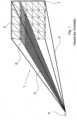
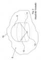
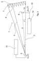
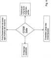
1 - den grundsätzlichen Aufbau einer bekannten GTEM-Zelle in perspektivischer Darstellung und2 - eine beispielhafte, zu untersuchende, bekannte Antenne in perspektivischer Darstellung und3 - eine Messanordnung zur Ausführung des erfindungsgemäßen Verfahrens mit einer GTEM-Zelle in Seitenansicht und4 - die Einflussgrößen des erfindungsgemäßen Verfahrens in schematischer Darstellung und5 - schematisch die Hauptfeldkomponenten eines TEM-Felds innerhalb einer GTEM-Zelle und6 - eine Draufsicht auf eine GTEM-Zelle und7 - den Verlauf des Feldwellenwiderstands in Querrichtung der GTEM-Zelle speziell als Quotient der Hauptfeldkomponenten und8 - einen beispielhaften Anregungspuls und9 - beispielhafte Impulsantworten der Antenne.
1 - the basic structure of a known GTEM cell in perspective view and2 - an exemplary known antenna to be examined in perspective view and3 - a measuring arrangement for carrying out the method according to the invention with a GTEM cell in side view and4 - the influencing factors of the method according to the invention in a schematic representation and5 - schematically the main field components of a TEM field within a GTEM cell and6 - a top view of a GTEM cell and7 - the course of the field wave resistance in the transverse direction of the GTEM cell specifically as a quotient of the main field components and8 - an exemplary excitation pulse and9 - exemplary impulse responses of the antenna.
In den Figuren werden gleiche Bezugszeichen für einander entsprechende Elemente verwendet.In the figures, the same reference symbols are used for corresponding elements.
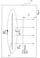
Als Beispiel für einen Wellenleiter wird nachfolgend eine GTEM-Zelle beschrieben. Wie in
Das Septum 5 ist innerhalb der GTEM-Zelle 1 so angeordnet, dass sich ein Leitungswellenwiderstand von 50 Ω einstellt, der über die Länge der GTEM-Zelle 1 konstant ist. Zur Einspeisung von Signalen weist die GTEM-Zelle 1 einen elektrischen Koaxialanschluss 4 für eine koaxiale Zuleitung auf. Der Innenleiter des Koaxialanschlusses 4 geht von der Anschlussstelle aus kontinuierlich in das Septum 5 der GTEM-Zelle 1 über. Der Außenleiter des Koaxialanschlusses 4 geht von der Anschlussstelle aus kontinuierlich in den Außenleiter der GTEM-Zelle 1, d.h. in das metallische Außengehäuse 2, über.The
Die
Die
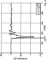
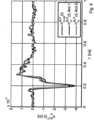
Zur Durchführung des erfindungsgemäßen Verfahrens wird ein Anregungspuls utx(t) von dem Pulsgenerator 13 in die GTEM-Zelle 1 eingespeist. Die sich dabei bildende und in Richtung der Antenne 8 ausbreitende elektromagnetische Welle trifft zu einem Zeitpunkt auf die Antenne 8 auf und erzeugt ein Antwortsignal urx(t), das von der Signalerfassungseinrichtung 14 aufgezeichnet wird.To carry out the method according to the invention, an excitation pulse utx (t) is fed from the
Die
Die zweite Einflussgröße ist die erwartete Länge des Antwortpulses der Antenne. Die erwartete Länge muss in Einklang mit der Pulspausendauer stehen, sodass nicht Störungen durch reflektierte Wellen beispielsweise gegen Ende des Antwortsignals auf die hinlaufende Welle diesem Antwortsignal überlagert werden.The second influencing factor is the expected length of the antenna's response pulse. The expected length must be consistent with the pulse pause duration so that interference from reflected waves, for example towards the end of the response signal, is not superimposed on the incoming wave.
Die dritte Einflussgröße ist die Anregungspulsbreite, d.h. die Dauer des Anregungssignals. Diese sollte wesentlich kürzer sein als die Pulspausendauer, was z.B. durch Verwendung eines Ultrabreitbandpulses der nachfolgend beschriebenen Art möglich ist.The third influencing factor is the excitation pulse width, i.e. the duration of the excitation signal. This should be significantly shorter than the pulse pause duration, which is possible, for example, by using an ultra-wideband pulse of the type described below.
Als vierte Einflussgröße ist die Antennengröße zu berücksichtigen, die in einem sinnvollen Verhältnis zum Querschnitt der GTEM-Zelle stehen soll, sodass Feldverzerrungen durch die Antennengröße vernachlässigbar werden. Als Faustregel für das Beispiel der Konusantenne gilt, dass die Querschnittsfläche der GTEM-Zelle im Bereich der Position der zu untersuchenden Antenne wenigstens 25mal so groß oder ca. 5 % der Querschnittsfläche sein sollte wie der Querschnitt der Antenne in derselben Querschnittsebene.The fourth influencing factor is the antenna size, which should be in a reasonable ratio to the cross-section of the GTEM cell so that field distortions caused by the antenna size are negligible. As a rule of thumb for the example of the cone antenna, the cross-sectional area of the GTEM cell in the area of the position of the antenna to be examined should be at least 25 times as large or approximately 5% of the cross-sectional area as the cross-section of the antenna in the same cross-sectional plane.
In der
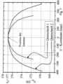
Die
Die
Die
Das Antwortsignal der Antenne wird als Spannungsverlauf urx(t) aufgezeichnet. Die Empfangsimpulsantwort hAUTrx(t) verknüpft im Allgemeinen das als Spannungsgröße vorliegende Antwortsignal der Antenne urx(t) mit dem im Empfangsfall auf die Antenne einfallenden drei elektrischen Feldkomponenten (Ex, Ey, Ez). Die Einheit einer solchen Impulsantwort wird daher für gewöhnlich in [m] angegeben. Das Antwortsignal urx(t) enthält grundsätzlich eine Überlagerung der in die verschiedenen Koordinatenrichtungen des Koordinatensystems gerichteten Komponenten eines Impulsantwortvektors hAUTrx(t) = (hx(t), hy(t), hz(t)) (AUT = antenna under test). In Folge der Ausbreitung der Welle als reines 2-Komponenten-TEM-Feld in kartesischen Koordinaten, wie es entlang der Mittelachse der GTEM-Zelle wie beschrieben vorliegt, können die x- und z-Anteile vernachlässigt werden, so dass sich die zur Bestimmung der Antennencharakteristik zu ermittelnde Impulsantwort hAUTrx,y (t) aus dem y-Anteil wie folgt polarisationsrein ergibt:
Hierbei repräsentiert der Operator *-1 eine inverse Faltungsoperation. Die Größe αPL ist eine für die verwendete GTEM-Zelle typische Dämpfungskonstante. Mit dem Index „TG“ wird angegeben, dass es sich um einen zeitlichen Anteil des Antwortsignals handelt, nämlich den für die Bestimmung des Charakteristikums der Antenne ausgewerteten Zeitabschnitt von urx(t), bei dem das Antwortsignal nur hinlaufende Wellen und keine Störeinflüsse durch Reflektionen umfasst und zudem das elektromagnetische Feld am Ort der Antenne ein TEM-Feld ist.Here, the operator *-1 represents an inverse convolution operation. The value αPL is an attenuation constant typical for the GTEM cell used. The index "TG" indicates that this is a temporal portion of the response signal, namely the time period of urx (t) evaluated to determine the characteristics of the antenna, in which the response signal only includes waves traveling inwards and no interference from reflections, and in addition, the electromagnetic field at the location of the antenna is a TEM field.
Die
Claims (14)
Translated fromGermanPriority Applications (8)
| Application Number | Priority Date | Filing Date | Title |
|---|---|---|---|
| DE102009037336.5ADE102009037336B4 (en) | 2009-08-14 | 2009-08-14 | Antenna characterization in a waveguide |
| HK12112783.2AHK1172090B (en) | 2009-08-14 | 2010-08-10 | Antenna characterisation in a waveguide |
| CA2769881ACA2769881C (en) | 2009-08-14 | 2010-08-10 | Antenna characterisation in a waveguide |
| EP10743036AEP2464985A1 (en) | 2009-08-14 | 2010-08-10 | Antenna characterisation in a waveguide |
| PCT/EP2010/004882WO2011018206A1 (en) | 2009-08-14 | 2010-08-10 | Antenna characterisation in a waveguide |
| US13/390,428US9279845B2 (en) | 2009-08-14 | 2010-08-10 | Antenna characterization in a waveguide |
| KR1020127006718AKR101746006B1 (en) | 2009-08-14 | 2010-08-10 | Antenna characterisation in a waveguide |
| CN201080046371.3ACN102576044B (en) | 2009-08-14 | 2010-08-10 | The characteristic of the antenna in waveguide is determined |
Applications Claiming Priority (1)
| Application Number | Priority Date | Filing Date | Title |
|---|---|---|---|
| DE102009037336.5ADE102009037336B4 (en) | 2009-08-14 | 2009-08-14 | Antenna characterization in a waveguide |
Publications (2)
| Publication Number | Publication Date |
|---|---|
| DE102009037336A1 DE102009037336A1 (en) | 2011-08-04 |
| DE102009037336B4true DE102009037336B4 (en) | 2024-10-31 |
Family
ID=43032992
Family Applications (1)
| Application Number | Title | Priority Date | Filing Date |
|---|---|---|---|
| DE102009037336.5AActiveDE102009037336B4 (en) | 2009-08-14 | 2009-08-14 | Antenna characterization in a waveguide |
Country Status (7)
| Country | Link |
|---|---|
| US (1) | US9279845B2 (en) |
| EP (1) | EP2464985A1 (en) |
| KR (1) | KR101746006B1 (en) |
| CN (1) | CN102576044B (en) |
| CA (1) | CA2769881C (en) |
| DE (1) | DE102009037336B4 (en) |
| WO (1) | WO2011018206A1 (en) |
Families Citing this family (124)
| Publication number | Priority date | Publication date | Assignee | Title |
|---|---|---|---|---|
| CN102866375B (en)* | 2012-09-07 | 2014-12-17 | 广东电网公司电力科学研究院 | System and method for calibrating receiving performance of partial-discharge ultrahigh frequency detection device |
| US9999038B2 (en) | 2013-05-31 | 2018-06-12 | At&T Intellectual Property I, L.P. | Remote distributed antenna system |
| US9525524B2 (en) | 2013-05-31 | 2016-12-20 | At&T Intellectual Property I, L.P. | Remote distributed antenna system |
| US8897697B1 (en) | 2013-11-06 | 2014-11-25 | At&T Intellectual Property I, Lp | Millimeter-wave surface-wave communications |
| US10001553B2 (en)* | 2014-09-11 | 2018-06-19 | Cpg Technologies, Llc | Geolocation with guided surface waves |
| US9768833B2 (en) | 2014-09-15 | 2017-09-19 | At&T Intellectual Property I, L.P. | Method and apparatus for sensing a condition in a transmission medium of electromagnetic waves |
| US10063280B2 (en) | 2014-09-17 | 2018-08-28 | At&T Intellectual Property I, L.P. | Monitoring and mitigating conditions in a communication network |
| US9615269B2 (en) | 2014-10-02 | 2017-04-04 | At&T Intellectual Property I, L.P. | Method and apparatus that provides fault tolerance in a communication network |
| US9685992B2 (en) | 2014-10-03 | 2017-06-20 | At&T Intellectual Property I, L.P. | Circuit panel network and methods thereof |
| US9503189B2 (en) | 2014-10-10 | 2016-11-22 | At&T Intellectual Property I, L.P. | Method and apparatus for arranging communication sessions in a communication system |
| US9973299B2 (en) | 2014-10-14 | 2018-05-15 | At&T Intellectual Property I, L.P. | Method and apparatus for adjusting a mode of communication in a communication network |
| US9627768B2 (en) | 2014-10-21 | 2017-04-18 | At&T Intellectual Property I, L.P. | Guided-wave transmission device with non-fundamental mode propagation and methods for use therewith |
| US9577306B2 (en) | 2014-10-21 | 2017-02-21 | At&T Intellectual Property I, L.P. | Guided-wave transmission device and methods for use therewith |
| US9780834B2 (en) | 2014-10-21 | 2017-10-03 | At&T Intellectual Property I, L.P. | Method and apparatus for transmitting electromagnetic waves |
| US9769020B2 (en) | 2014-10-21 | 2017-09-19 | At&T Intellectual Property I, L.P. | Method and apparatus for responding to events affecting communications in a communication network |
| US9312919B1 (en) | 2014-10-21 | 2016-04-12 | At&T Intellectual Property I, Lp | Transmission device with impairment compensation and methods for use therewith |
| US9653770B2 (en) | 2014-10-21 | 2017-05-16 | At&T Intellectual Property I, L.P. | Guided wave coupler, coupling module and methods for use therewith |
| US9954287B2 (en) | 2014-11-20 | 2018-04-24 | At&T Intellectual Property I, L.P. | Apparatus for converting wireless signals and electromagnetic waves and methods thereof |
| US9461706B1 (en) | 2015-07-31 | 2016-10-04 | At&T Intellectual Property I, Lp | Method and apparatus for exchanging communication signals |
| US9800327B2 (en) | 2014-11-20 | 2017-10-24 | At&T Intellectual Property I, L.P. | Apparatus for controlling operations of a communication device and methods thereof |
| US10009067B2 (en) | 2014-12-04 | 2018-06-26 | At&T Intellectual Property I, L.P. | Method and apparatus for configuring a communication interface |
| US9997819B2 (en) | 2015-06-09 | 2018-06-12 | At&T Intellectual Property I, L.P. | Transmission medium and method for facilitating propagation of electromagnetic waves via a core |
| US10340573B2 (en) | 2016-10-26 | 2019-07-02 | At&T Intellectual Property I, L.P. | Launcher with cylindrical coupling device and methods for use therewith |
| US9544006B2 (en) | 2014-11-20 | 2017-01-10 | At&T Intellectual Property I, L.P. | Transmission device with mode division multiplexing and methods for use therewith |
| US9742462B2 (en) | 2014-12-04 | 2017-08-22 | At&T Intellectual Property I, L.P. | Transmission medium and communication interfaces and methods for use therewith |
| US10243784B2 (en) | 2014-11-20 | 2019-03-26 | At&T Intellectual Property I, L.P. | System for generating topology information and methods thereof |
| US9876570B2 (en) | 2015-02-20 | 2018-01-23 | At&T Intellectual Property I, Lp | Guided-wave transmission device with non-fundamental mode propagation and methods for use therewith |
| US9749013B2 (en) | 2015-03-17 | 2017-08-29 | At&T Intellectual Property I, L.P. | Method and apparatus for reducing attenuation of electromagnetic waves guided by a transmission medium |
| CN104777443B (en)* | 2015-03-25 | 2017-09-29 | 上海交通大学 | The performance testing device and method of testing of a kind of partial-discharge ultrahigh-frequency sensor |
| US10224981B2 (en) | 2015-04-24 | 2019-03-05 | At&T Intellectual Property I, Lp | Passive electrical coupling device and methods for use therewith |
| US9705561B2 (en) | 2015-04-24 | 2017-07-11 | At&T Intellectual Property I, L.P. | Directional coupling device and methods for use therewith |
| US9793954B2 (en) | 2015-04-28 | 2017-10-17 | At&T Intellectual Property I, L.P. | Magnetic coupling device and methods for use therewith |
| US9748626B2 (en) | 2015-05-14 | 2017-08-29 | At&T Intellectual Property I, L.P. | Plurality of cables having different cross-sectional shapes which are bundled together to form a transmission medium |
| US9490869B1 (en) | 2015-05-14 | 2016-11-08 | At&T Intellectual Property I, L.P. | Transmission medium having multiple cores and methods for use therewith |
| US9871282B2 (en) | 2015-05-14 | 2018-01-16 | At&T Intellectual Property I, L.P. | At least one transmission medium having a dielectric surface that is covered at least in part by a second dielectric |
| US10650940B2 (en) | 2015-05-15 | 2020-05-12 | At&T Intellectual Property I, L.P. | Transmission medium having a conductive material and methods for use therewith |
| US9917341B2 (en) | 2015-05-27 | 2018-03-13 | At&T Intellectual Property I, L.P. | Apparatus and method for launching electromagnetic waves and for modifying radial dimensions of the propagating electromagnetic waves |
| US10812174B2 (en) | 2015-06-03 | 2020-10-20 | At&T Intellectual Property I, L.P. | Client node device and methods for use therewith |
| US9866309B2 (en) | 2015-06-03 | 2018-01-09 | At&T Intellectual Property I, Lp | Host node device and methods for use therewith |
| US9912381B2 (en) | 2015-06-03 | 2018-03-06 | At&T Intellectual Property I, Lp | Network termination and methods for use therewith |
| US9913139B2 (en) | 2015-06-09 | 2018-03-06 | At&T Intellectual Property I, L.P. | Signal fingerprinting for authentication of communicating devices |
| US9820146B2 (en) | 2015-06-12 | 2017-11-14 | At&T Intellectual Property I, L.P. | Method and apparatus for authentication and identity management of communicating devices |
| US9865911B2 (en) | 2015-06-25 | 2018-01-09 | At&T Intellectual Property I, L.P. | Waveguide system for slot radiating first electromagnetic waves that are combined into a non-fundamental wave mode second electromagnetic wave on a transmission medium |
| US9509415B1 (en) | 2015-06-25 | 2016-11-29 | At&T Intellectual Property I, L.P. | Methods and apparatus for inducing a fundamental wave mode on a transmission medium |
| US9640850B2 (en) | 2015-06-25 | 2017-05-02 | At&T Intellectual Property I, L.P. | Methods and apparatus for inducing a non-fundamental wave mode on a transmission medium |
| US9853342B2 (en) | 2015-07-14 | 2017-12-26 | At&T Intellectual Property I, L.P. | Dielectric transmission medium connector and methods for use therewith |
| US9847566B2 (en) | 2015-07-14 | 2017-12-19 | At&T Intellectual Property I, L.P. | Method and apparatus for adjusting a field of a signal to mitigate interference |
| US10148016B2 (en) | 2015-07-14 | 2018-12-04 | At&T Intellectual Property I, L.P. | Apparatus and methods for communicating utilizing an antenna array |
| US10205655B2 (en) | 2015-07-14 | 2019-02-12 | At&T Intellectual Property I, L.P. | Apparatus and methods for communicating utilizing an antenna array and multiple communication paths |
| US9628116B2 (en) | 2015-07-14 | 2017-04-18 | At&T Intellectual Property I, L.P. | Apparatus and methods for transmitting wireless signals |
| US9882257B2 (en) | 2015-07-14 | 2018-01-30 | At&T Intellectual Property I, L.P. | Method and apparatus for launching a wave mode that mitigates interference |
| US10044409B2 (en) | 2015-07-14 | 2018-08-07 | At&T Intellectual Property I, L.P. | Transmission medium and methods for use therewith |
| US10090606B2 (en) | 2015-07-15 | 2018-10-02 | At&T Intellectual Property I, L.P. | Antenna system with dielectric array and methods for use therewith |
| US9871283B2 (en) | 2015-07-23 | 2018-01-16 | At&T Intellectual Property I, Lp | Transmission medium having a dielectric core comprised of plural members connected by a ball and socket configuration |
| US9948333B2 (en) | 2015-07-23 | 2018-04-17 | At&T Intellectual Property I, L.P. | Method and apparatus for wireless communications to mitigate interference |
| US9912027B2 (en) | 2015-07-23 | 2018-03-06 | At&T Intellectual Property I, L.P. | Method and apparatus for exchanging communication signals |
| US9749053B2 (en) | 2015-07-23 | 2017-08-29 | At&T Intellectual Property I, L.P. | Node device, repeater and methods for use therewith |
| US9967173B2 (en) | 2015-07-31 | 2018-05-08 | At&T Intellectual Property I, L.P. | Method and apparatus for authentication and identity management of communicating devices |
| US9735833B2 (en) | 2015-07-31 | 2017-08-15 | At&T Intellectual Property I, L.P. | Method and apparatus for communications management in a neighborhood network |
| US9904535B2 (en) | 2015-09-14 | 2018-02-27 | At&T Intellectual Property I, L.P. | Method and apparatus for distributing software |
| US9769128B2 (en) | 2015-09-28 | 2017-09-19 | At&T Intellectual Property I, L.P. | Method and apparatus for encryption of communications over a network |
| US9729197B2 (en) | 2015-10-01 | 2017-08-08 | At&T Intellectual Property I, L.P. | Method and apparatus for communicating network management traffic over a network |
| US9876264B2 (en) | 2015-10-02 | 2018-01-23 | At&T Intellectual Property I, Lp | Communication system, guided wave switch and methods for use therewith |
| US10355367B2 (en) | 2015-10-16 | 2019-07-16 | At&T Intellectual Property I, L.P. | Antenna structure for exchanging wireless signals |
| CN107305229B (en)* | 2016-04-22 | 2020-08-14 | 迈普通信技术股份有限公司 | Method and device for evaluating quality of passive link |
| US9860075B1 (en) | 2016-08-26 | 2018-01-02 | At&T Intellectual Property I, L.P. | Method and communication node for broadband distribution |
| US10811767B2 (en) | 2016-10-21 | 2020-10-20 | At&T Intellectual Property I, L.P. | System and dielectric antenna with convex dielectric radome |
| US10312567B2 (en) | 2016-10-26 | 2019-06-04 | At&T Intellectual Property I, L.P. | Launcher with planar strip antenna and methods for use therewith |
| US10224634B2 (en) | 2016-11-03 | 2019-03-05 | At&T Intellectual Property I, L.P. | Methods and apparatus for adjusting an operational characteristic of an antenna |
| US10225025B2 (en) | 2016-11-03 | 2019-03-05 | At&T Intellectual Property I, L.P. | Method and apparatus for detecting a fault in a communication system |
| US10291334B2 (en) | 2016-11-03 | 2019-05-14 | At&T Intellectual Property I, L.P. | System for detecting a fault in a communication system |
| US10498044B2 (en) | 2016-11-03 | 2019-12-03 | At&T Intellectual Property I, L.P. | Apparatus for configuring a surface of an antenna |
| US10535928B2 (en) | 2016-11-23 | 2020-01-14 | At&T Intellectual Property I, L.P. | Antenna system and methods for use therewith |
| US10090594B2 (en) | 2016-11-23 | 2018-10-02 | At&T Intellectual Property I, L.P. | Antenna system having structural configurations for assembly |
| US10340601B2 (en) | 2016-11-23 | 2019-07-02 | At&T Intellectual Property I, L.P. | Multi-antenna system and methods for use therewith |
| US10340603B2 (en) | 2016-11-23 | 2019-07-02 | At&T Intellectual Property I, L.P. | Antenna system having shielded structural configurations for assembly |
| US10178445B2 (en) | 2016-11-23 | 2019-01-08 | At&T Intellectual Property I, L.P. | Methods, devices, and systems for load balancing between a plurality of waveguides |
| US10361489B2 (en) | 2016-12-01 | 2019-07-23 | At&T Intellectual Property I, L.P. | Dielectric dish antenna system and methods for use therewith |
| US10305190B2 (en) | 2016-12-01 | 2019-05-28 | At&T Intellectual Property I, L.P. | Reflecting dielectric antenna system and methods for use therewith |
| US10382976B2 (en) | 2016-12-06 | 2019-08-13 | At&T Intellectual Property I, L.P. | Method and apparatus for managing wireless communications based on communication paths and network device positions |
| US10020844B2 (en) | 2016-12-06 | 2018-07-10 | T&T Intellectual Property I, L.P. | Method and apparatus for broadcast communication via guided waves |
| US10755542B2 (en) | 2016-12-06 | 2020-08-25 | At&T Intellectual Property I, L.P. | Method and apparatus for surveillance via guided wave communication |
| US10135145B2 (en) | 2016-12-06 | 2018-11-20 | At&T Intellectual Property I, L.P. | Apparatus and methods for generating an electromagnetic wave along a transmission medium |
| US10727599B2 (en) | 2016-12-06 | 2020-07-28 | At&T Intellectual Property I, L.P. | Launcher with slot antenna and methods for use therewith |
| US10326494B2 (en) | 2016-12-06 | 2019-06-18 | At&T Intellectual Property I, L.P. | Apparatus for measurement de-embedding and methods for use therewith |
| US10694379B2 (en) | 2016-12-06 | 2020-06-23 | At&T Intellectual Property I, L.P. | Waveguide system with device-based authentication and methods for use therewith |
| US10637149B2 (en) | 2016-12-06 | 2020-04-28 | At&T Intellectual Property I, L.P. | Injection molded dielectric antenna and methods for use therewith |
| US9927517B1 (en) | 2016-12-06 | 2018-03-27 | At&T Intellectual Property I, L.P. | Apparatus and methods for sensing rainfall |
| US10439675B2 (en) | 2016-12-06 | 2019-10-08 | At&T Intellectual Property I, L.P. | Method and apparatus for repeating guided wave communication signals |
| US10819035B2 (en) | 2016-12-06 | 2020-10-27 | At&T Intellectual Property I, L.P. | Launcher with helical antenna and methods for use therewith |
| US10359749B2 (en) | 2016-12-07 | 2019-07-23 | At&T Intellectual Property I, L.P. | Method and apparatus for utilities management via guided wave communication |
| US10389029B2 (en) | 2016-12-07 | 2019-08-20 | At&T Intellectual Property I, L.P. | Multi-feed dielectric antenna system with core selection and methods for use therewith |
| US9893795B1 (en) | 2016-12-07 | 2018-02-13 | At&T Intellectual Property I, Lp | Method and repeater for broadband distribution |
| US10446936B2 (en) | 2016-12-07 | 2019-10-15 | At&T Intellectual Property I, L.P. | Multi-feed dielectric antenna system and methods for use therewith |
| US10139820B2 (en) | 2016-12-07 | 2018-11-27 | At&T Intellectual Property I, L.P. | Method and apparatus for deploying equipment of a communication system |
| US10027397B2 (en) | 2016-12-07 | 2018-07-17 | At&T Intellectual Property I, L.P. | Distributed antenna system and methods for use therewith |
| US10168695B2 (en) | 2016-12-07 | 2019-01-01 | At&T Intellectual Property I, L.P. | Method and apparatus for controlling an unmanned aircraft |
| US10243270B2 (en) | 2016-12-07 | 2019-03-26 | At&T Intellectual Property I, L.P. | Beam adaptive multi-feed dielectric antenna system and methods for use therewith |
| US10547348B2 (en) | 2016-12-07 | 2020-01-28 | At&T Intellectual Property I, L.P. | Method and apparatus for switching transmission mediums in a communication system |
| US9911020B1 (en) | 2016-12-08 | 2018-03-06 | At&T Intellectual Property I, L.P. | Method and apparatus for tracking via a radio frequency identification device |
| US10777873B2 (en) | 2016-12-08 | 2020-09-15 | At&T Intellectual Property I, L.P. | Method and apparatus for mounting network devices |
| US10326689B2 (en) | 2016-12-08 | 2019-06-18 | At&T Intellectual Property I, L.P. | Method and system for providing alternative communication paths |
| US10916969B2 (en) | 2016-12-08 | 2021-02-09 | At&T Intellectual Property I, L.P. | Method and apparatus for providing power using an inductive coupling |
| US10601494B2 (en) | 2016-12-08 | 2020-03-24 | At&T Intellectual Property I, L.P. | Dual-band communication device and method for use therewith |
| US10411356B2 (en) | 2016-12-08 | 2019-09-10 | At&T Intellectual Property I, L.P. | Apparatus and methods for selectively targeting communication devices with an antenna array |
| US10530505B2 (en) | 2016-12-08 | 2020-01-07 | At&T Intellectual Property I, L.P. | Apparatus and methods for launching electromagnetic waves along a transmission medium |
| US10938108B2 (en) | 2016-12-08 | 2021-03-02 | At&T Intellectual Property I, L.P. | Frequency selective multi-feed dielectric antenna system and methods for use therewith |
| US10027427B2 (en) | 2016-12-08 | 2018-07-17 | At&T Intellectual Property I, L.P. | Apparatus and methods for measuring signals |
| US9998870B1 (en) | 2016-12-08 | 2018-06-12 | At&T Intellectual Property I, L.P. | Method and apparatus for proximity sensing |
| US10069535B2 (en) | 2016-12-08 | 2018-09-04 | At&T Intellectual Property I, L.P. | Apparatus and methods for launching electromagnetic waves having a certain electric field structure |
| US10389037B2 (en) | 2016-12-08 | 2019-08-20 | At&T Intellectual Property I, L.P. | Apparatus and methods for selecting sections of an antenna array and use therewith |
| US10103422B2 (en) | 2016-12-08 | 2018-10-16 | At&T Intellectual Property I, L.P. | Method and apparatus for mounting network devices |
| US9838896B1 (en) | 2016-12-09 | 2017-12-05 | At&T Intellectual Property I, L.P. | Method and apparatus for assessing network coverage |
| US10340983B2 (en) | 2016-12-09 | 2019-07-02 | At&T Intellectual Property I, L.P. | Method and apparatus for surveying remote sites via guided wave communications |
| US10264586B2 (en) | 2016-12-09 | 2019-04-16 | At&T Mobility Ii Llc | Cloud-based packet controller and methods for use therewith |
| US9973940B1 (en) | 2017-02-27 | 2018-05-15 | At&T Intellectual Property I, L.P. | Apparatus and methods for dynamic impedance matching of a guided wave launcher |
| US10298293B2 (en) | 2017-03-13 | 2019-05-21 | At&T Intellectual Property I, L.P. | Apparatus of communication utilizing wireless network devices |
| CN107202929B (en)* | 2017-06-23 | 2019-05-07 | 中国电子科技集团公司第五十四研究所 | A method for measuring the loss of rectangular waveguide components |
| EP3765834A4 (en)* | 2018-03-13 | 2021-12-15 | University of Louisville | FREQUENCY SELECTIVE SURFACES FOR TRACKING, MARKING AND IDENTIFICATION |
| CN112394233B (en)* | 2019-08-16 | 2024-07-30 | 稜研科技股份有限公司 | Antenna packaging verification board |
| SE544144C2 (en)* | 2020-03-03 | 2022-01-11 | Bluetest Ab | A hybrid antenna measurement chamber |
| CN111537808B (en)* | 2020-04-28 | 2022-07-15 | 中国人民解放军63660部队 | Ultra-wide spectrum high-power microwave sensor based on aqueous medium |
| EP4270020B1 (en)* | 2022-04-27 | 2025-07-30 | Rosenberger Hochfrequenztechnik GmbH & Co. KG | Intermodulation measuring method, intermodulation measuring device, and computer program for determining an intermodulation source in a transmission line |
| CN117590092B (en)* | 2023-10-16 | 2024-09-17 | 人天通信集团有限公司 | Antenna radiation efficiency measuring method and system and electronic equipment |
Citations (2)
| Publication number | Priority date | Publication date | Assignee | Title |
|---|---|---|---|---|
| DE3722406A1 (en) | 1987-07-07 | 1988-10-20 | Werner Prof Dr Ing Wiesbeck | Method for antenna measurements by means of the complex reflection factors of the object being measured |
| DE60218223T2 (en) | 2001-12-21 | 2007-12-13 | Fizzle Holdings Ltd., Douglas | ANTENNA MEASURING SYSTEM |
Family Cites Families (4)
| Publication number | Priority date | Publication date | Assignee | Title |
|---|---|---|---|---|
| US5404098A (en)* | 1992-08-14 | 1995-04-04 | The Electro-Mechanics Company | Method and apparatus for improved correlation of electromagnetic emmission test data |
| US6437748B1 (en)* | 2000-07-20 | 2002-08-20 | The Ohio State University | Tapered anechoic chamber |
| JP2007271317A (en) | 2006-03-30 | 2007-10-18 | Murata Mfg Co Ltd | Emi measuring instrument, and emi measuring method |
| KR100981256B1 (en) | 2008-05-23 | 2010-09-10 | 한국전자통신연구원 | Antenna Radiation Performance Measurement System and Method |
- 2009
- 2009-08-14DEDE102009037336.5Apatent/DE102009037336B4/enactiveActive
- 2010
- 2010-08-10CNCN201080046371.3Apatent/CN102576044B/enactiveActive
- 2010-08-10USUS13/390,428patent/US9279845B2/enactiveActive
- 2010-08-10EPEP10743036Apatent/EP2464985A1/ennot_activeCeased
- 2010-08-10KRKR1020127006718Apatent/KR101746006B1/ennot_activeExpired - Fee Related
- 2010-08-10WOPCT/EP2010/004882patent/WO2011018206A1/enactiveApplication Filing
- 2010-08-10CACA2769881Apatent/CA2769881C/enactiveActive
Patent Citations (2)
| Publication number | Priority date | Publication date | Assignee | Title |
|---|---|---|---|---|
| DE3722406A1 (en) | 1987-07-07 | 1988-10-20 | Werner Prof Dr Ing Wiesbeck | Method for antenna measurements by means of the complex reflection factors of the object being measured |
| DE60218223T2 (en) | 2001-12-21 | 2007-12-13 | Fizzle Holdings Ltd., Douglas | ANTENNA MEASURING SYSTEM |
Non-Patent Citations (6)
| Title |
|---|
| HUI, Ping: Application of GTEM cells to wireless communication transceiver designs. In: Microwave journal, Vol. 46, 2003, No. 9, S. 168-181. - ISSN 0192-6225* |
| HUI, Ping: Application of GTEM cells to wireless communication transceiver designs. In: Microwavejournal, Vol. 46, 2003, No. 9, S. 168-181. - ISSN 0192-6225 |
| Thye, H.; Armbrecht, G.; Koch, M.: Pulse Propagation in Gigahertz Transverse Electromagnetic Cells. In: IEEE Transactions on Electromagnetic Compatibility, Vol. 51, No. 3, August 2009 (first published May 5, 2009), S. 592-603 |
| THYE, Holger, ARMBRECHT, Gunnar, KOCH, Michael: Pulse Propagation in Gigahertz Transverse Electromagnetic Cells. In: IEEE Transactions on electromagnetic compatibility, Vol. 51, No. 3, August 2009 (first published May 5, 2009), S. 592-603* |
| THYE, Holger, ARMBRECHT, Gunnar, KOCH, Michael: System Theoretical Analysis of the GTEM Cell in Time Domain. In: 2008 IEEE International Symposium on Electromagnetic Compatibility - EMC Europe, 8.-12. September 2008 in Hamburg (Germany), S. 1-5 |
| THYE, Holger, ZAMOW, Dirk, KOCH, Michael, GARBE, Heyno: Aspects of Using the IEC 61000-4-20 for Transient Testing with Broadband Signals. In: 2008 IEEE International Symposium on Electromagnetic Compatibility, August 2008, S. 1-5 |
Also Published As
| Publication number | Publication date |
|---|---|
| US9279845B2 (en) | 2016-03-08 |
| WO2011018206A1 (en) | 2011-02-17 |
| CA2769881A1 (en) | 2011-02-17 |
| CN102576044B (en) | 2015-10-21 |
| HK1172090A1 (en) | 2013-04-12 |
| KR20120062778A (en) | 2012-06-14 |
| KR101746006B1 (en) | 2017-06-12 |
| CA2769881C (en) | 2017-09-05 |
| DE102009037336A1 (en) | 2011-08-04 |
| US20120146861A1 (en) | 2012-06-14 |
| CN102576044A (en) | 2012-07-11 |
| EP2464985A1 (en) | 2012-06-20 |
Similar Documents
| Publication | Publication Date | Title |
|---|---|---|
| DE102009037336B4 (en) | Antenna characterization in a waveguide | |
| EP3467531A1 (en) | Magnetic resonance tomograph with active interference suppression and method for suppressing interference in a magnetic resonance tomograph | |
| DE60015981T2 (en) | METHOD AND DEVICE FOR MEASURING THE NEAR VIEW OF UNCONTROLLED ELECTROMAGNETIC RADIATIONS | |
| DE112009001121T5 (en) | A method of measuring a radiated power, a coupler for measuring a radiated power, and a device for measuring a radiated power | |
| DE112006002864T5 (en) | Device for testing the susceptibility to interference | |
| DE112018007971T5 (en) | NEAR FIELD ANTENNA FOR RADIO REMOTE CONTROL OF AN ANTENNA ARRAY | |
| DE10393724T5 (en) | Probe for combined signals | |
| DE69320465T2 (en) | TEST APPARATUS FOR ELECTROMAGNETIC INTERFERENCE | |
| EP2320240A2 (en) | Device and method for measuring a radiation field | |
| DE60014246T2 (en) | Device for measuring characteristics of an electromagnetic field, in particular for an antenna radiation diagram | |
| DE102007034851B4 (en) | Device and method for determining the electromagnetic emission and immunity to interference | |
| DE102015102636B4 (en) | Test chamber and procedure for the EMC test | |
| DE19917661B4 (en) | Method and device for measuring electromagnetic waves | |
| EP3980800B1 (en) | Use of a dipole antenna array for hybrid mr-pet and mr-spect scans and mr-pet or mr-spect tomograph with a dipole antenna array | |
| DE69419380T2 (en) | Compact and portable device for measuring the reflection coefficient of a structure irradiated with microwaves | |
| DE69408600T2 (en) | Method of measuring the inside diameter of a pipe | |
| DE602006000863T2 (en) | Method for mounting an antenna, antenna mounted according to this method and device for carrying out the method | |
| EP2246707B1 (en) | Method and assembly for measuring the alignment characteristics of an antenna that is to be tested | |
| DE102004037718B4 (en) | Method for detecting defects on electrically conductive or dielectric layers and test device for this purpose | |
| DE102013008570B4 (en) | Method for operating an electromagnetic ultrasonic transducer | |
| EP2302338A1 (en) | Method for determining characteristics of media and measuring device for this method | |
| DE102007008202B4 (en) | Test system for a radar device | |
| DE112004002808B4 (en) | A method and apparatus for measuring high frequency electrical characteristics of an electronic device and method for calibrating high frequency electrical characteristic measuring devices | |
| EP2133710A1 (en) | Method for testing a transponder for aircraft radio and measuring system | |
| DE102012024373B4 (en) | Mode swirling chamber for testing electronic circuits |
Legal Events
| Date | Code | Title | Description |
|---|---|---|---|
| R082 | Change of representative | Representative=s name:ZEITLER, VOLPERT, KANDLBINDER, 80539 MUENCHEN, DE Representative=s name:ZEITLER, VOLPERT, KANDLBINDER, DE | |
| R081 | Change of applicant/patentee | Owner name:ROSENBERGER HOCHFREQUENZTECHNIK GMBH & CO. KG, DE Free format text:FORMER OWNER: GOTTFRIED WILHELM LEIBNIZ UNIVERSITAET HANNOVER, 30167 HANNOVER, DE Effective date:20120327 | |
| R082 | Change of representative | Representative=s name:ZEITLER VOLPERT KANDLBINDER PATENTANWAELTE PAR, DE Effective date:20120228 Representative=s name:ZEITLER VOLPERT KANDLBINDER PATENT- UND RECHTS, DE Effective date:20120228 | |
| R016 | Response to examination communication | ||
| R082 | Change of representative | Representative=s name:KANDLBINDER, MARKUS, DIPL.-PHYS., DE | |
| R016 | Response to examination communication | ||
| R018 | Grant decision by examination section/examining division | ||
| R020 | Patent grant now final |