DE102009037299A1 - Device and treatment chamber for the thermal treatment of substrates - Google Patents
Device and treatment chamber for the thermal treatment of substratesDownload PDFInfo
- Publication number
- DE102009037299A1 DE102009037299A1DE102009037299ADE102009037299ADE102009037299A1DE 102009037299 A1DE102009037299 A1DE 102009037299A1DE 102009037299 ADE102009037299 ADE 102009037299ADE 102009037299 ADE102009037299 ADE 102009037299ADE 102009037299 A1DE102009037299 A1DE 102009037299A1
- Authority
- DE
- Germany
- Prior art keywords
- treatment chamber
- gas
- substrate
- chamber
- heating
- Prior art date
- Legal status (The legal status is an assumption and is not a legal conclusion. Google has not performed a legal analysis and makes no representation as to the accuracy of the status listed.)
- Withdrawn
Links
- 239000000758substrateSubstances0.000titleclaimsabstractdescription105
- 238000007669thermal treatmentMethods0.000titledescription7
- 238000010438heat treatmentMethods0.000claimsabstractdescription89
- 238000001816coolingMethods0.000claimsabstractdescription47
- 238000009413insulationMethods0.000claimsdescription8
- 238000000034methodMethods0.000claimsdescription8
- 239000000463materialSubstances0.000claimsdescription7
- 238000001035dryingMethods0.000claimsdescription5
- 239000007788liquidSubstances0.000claimsdescription3
- 238000003860storageMethods0.000claimsdescription3
- 238000005496temperingMethods0.000claimsdescription3
- 238000004140cleaningMethods0.000claimsdescription2
- 238000003780insertionMethods0.000claims1
- 230000037431insertionEffects0.000claims1
- 239000007789gasSubstances0.000description86
- 238000000576coating methodMethods0.000description5
- 239000010410layerSubstances0.000description4
- 238000004519manufacturing processMethods0.000description4
- 230000005855radiationEffects0.000description4
- 239000011521glassSubstances0.000description3
- 239000010409thin filmSubstances0.000description3
- KTSFMFGEAAANTF-UHFFFAOYSA-N[Cu].[Se].[Se].[In]Chemical compound[Cu].[Se].[Se].[In]KTSFMFGEAAANTF-UHFFFAOYSA-N0.000description2
- 239000012876carrier materialSubstances0.000description2
- 239000011248coating agentSubstances0.000description2
- 239000002826coolantSubstances0.000description2
- 230000005670electromagnetic radiationEffects0.000description2
- 238000005516engineering processMethods0.000description2
- 239000010453quartzSubstances0.000description2
- 230000001105regulatory effectEffects0.000description2
- 239000004065semiconductorSubstances0.000description2
- VYPSYNLAJGMNEJ-UHFFFAOYSA-Nsilicon dioxideInorganic materialsO=[Si]=OVYPSYNLAJGMNEJ-UHFFFAOYSA-N0.000description2
- BUHVIAUBTBOHAG-FOYDDCNASA-N(2r,3r,4s,5r)-2-[6-[[2-(3,5-dimethoxyphenyl)-2-(2-methylphenyl)ethyl]amino]purin-9-yl]-5-(hydroxymethyl)oxolane-3,4-diolChemical compoundCOC1=CC(OC)=CC(C(CNC=2C=3N=CN(C=3N=CN=2)[C@H]2[C@@H]([C@H](O)[C@@H](CO)O2)O)C=2C(=CC=CC=2)C)=C1BUHVIAUBTBOHAG-FOYDDCNASA-N0.000description1
- GYHNNYVSQQEPJS-UHFFFAOYSA-NGalliumChemical compound[Ga]GYHNNYVSQQEPJS-UHFFFAOYSA-N0.000description1
- BKQMNPVDJIHLPD-UHFFFAOYSA-NOS(=O)(=O)[Se]S(O)(=O)=OChemical compoundOS(=O)(=O)[Se]S(O)(=O)=OBKQMNPVDJIHLPD-UHFFFAOYSA-N0.000description1
- 238000005452bendingMethods0.000description1
- 239000012141concentrateSubstances0.000description1
- 239000000112cooling gasSubstances0.000description1
- HVMJUDPAXRRVQO-UHFFFAOYSA-Ncopper indiumChemical compound[Cu].[In]HVMJUDPAXRRVQO-UHFFFAOYSA-N0.000description1
- 238000007791dehumidificationMethods0.000description1
- 230000001419dependent effectEffects0.000description1
- 238000010586diagramMethods0.000description1
- 238000009826distributionMethods0.000description1
- 229910052733galliumInorganic materials0.000description1
- 239000002346layers by functionSubstances0.000description1
- 238000002310reflectometryMethods0.000description1
- 238000004381surface treatmentMethods0.000description1
- 231100000331toxicToxicity0.000description1
- 230000002588toxic effectEffects0.000description1
- 239000002341toxic gasSubstances0.000description1
Images
Classifications
- F—MECHANICAL ENGINEERING; LIGHTING; HEATING; WEAPONS; BLASTING
- F27—FURNACES; KILNS; OVENS; RETORTS
- F27B—FURNACES, KILNS, OVENS OR RETORTS IN GENERAL; OPEN SINTERING OR LIKE APPARATUS
- F27B9/00—Furnaces through which the charge is moved mechanically, e.g. of tunnel type; Similar furnaces in which the charge moves by gravity
- F27B9/30—Details, accessories or equipment specially adapted for furnaces of these types
- F27B9/3005—Details, accessories or equipment specially adapted for furnaces of these types arrangements for circulating gases
- C—CHEMISTRY; METALLURGY
- C03—GLASS; MINERAL OR SLAG WOOL
- C03B—MANUFACTURE, SHAPING, OR SUPPLEMENTARY PROCESSES
- C03B27/00—Tempering or quenching glass products
- C03B27/04—Tempering or quenching glass products using gas
- C03B27/0404—Nozzles, blow heads, blowing units or their arrangements, specially adapted for flat or bent glass sheets
- C—CHEMISTRY; METALLURGY
- C03—GLASS; MINERAL OR SLAG WOOL
- C03B—MANUFACTURE, SHAPING, OR SUPPLEMENTARY PROCESSES
- C03B27/00—Tempering or quenching glass products
- C03B27/04—Tempering or quenching glass products using gas
- C03B27/0417—Controlling or regulating for flat or bent glass sheets
- C—CHEMISTRY; METALLURGY
- C03—GLASS; MINERAL OR SLAG WOOL
- C03B—MANUFACTURE, SHAPING, OR SUPPLEMENTARY PROCESSES
- C03B27/00—Tempering or quenching glass products
- C03B27/04—Tempering or quenching glass products using gas
- C03B27/044—Tempering or quenching glass products using gas for flat or bent glass sheets being in a horizontal position
- C—CHEMISTRY; METALLURGY
- C03—GLASS; MINERAL OR SLAG WOOL
- C03B—MANUFACTURE, SHAPING, OR SUPPLEMENTARY PROCESSES
- C03B29/00—Reheating glass products for softening or fusing their surfaces; Fire-polishing; Fusing of margins
- C03B29/02—Reheating glass products for softening or fusing their surfaces; Fire-polishing; Fusing of margins in a discontinuous way
- C03B29/025—Glass sheets
- C—CHEMISTRY; METALLURGY
- C03—GLASS; MINERAL OR SLAG WOOL
- C03B—MANUFACTURE, SHAPING, OR SUPPLEMENTARY PROCESSES
- C03B29/00—Reheating glass products for softening or fusing their surfaces; Fire-polishing; Fusing of margins
- C03B29/04—Reheating glass products for softening or fusing their surfaces; Fire-polishing; Fusing of margins in a continuous way
- C03B29/06—Reheating glass products for softening or fusing their surfaces; Fire-polishing; Fusing of margins in a continuous way with horizontal displacement of the products
- C03B29/08—Glass sheets
- H—ELECTRICITY
- H01—ELECTRIC ELEMENTS
- H01L—SEMICONDUCTOR DEVICES NOT COVERED BY CLASS H10
- H01L21/00—Processes or apparatus adapted for the manufacture or treatment of semiconductor or solid state devices or of parts thereof
- H01L21/67—Apparatus specially adapted for handling semiconductor or electric solid state devices during manufacture or treatment thereof; Apparatus specially adapted for handling wafers during manufacture or treatment of semiconductor or electric solid state devices or components ; Apparatus not specifically provided for elsewhere
- H01L21/67005—Apparatus not specifically provided for elsewhere
- H01L21/67011—Apparatus for manufacture or treatment
- H01L21/67098—Apparatus for thermal treatment
- H01L21/67109—Apparatus for thermal treatment mainly by convection
- H—ELECTRICITY
- H01—ELECTRIC ELEMENTS
- H01L—SEMICONDUCTOR DEVICES NOT COVERED BY CLASS H10
- H01L21/00—Processes or apparatus adapted for the manufacture or treatment of semiconductor or solid state devices or of parts thereof
- H01L21/67—Apparatus specially adapted for handling semiconductor or electric solid state devices during manufacture or treatment thereof; Apparatus specially adapted for handling wafers during manufacture or treatment of semiconductor or electric solid state devices or components ; Apparatus not specifically provided for elsewhere
- H01L21/67005—Apparatus not specifically provided for elsewhere
- H01L21/67011—Apparatus for manufacture or treatment
- H01L21/67155—Apparatus for manufacturing or treating in a plurality of work-stations
- H01L21/67161—Apparatus for manufacturing or treating in a plurality of work-stations characterized by the layout of the process chambers
- H01L21/67173—Apparatus for manufacturing or treating in a plurality of work-stations characterized by the layout of the process chambers in-line arrangement
- H—ELECTRICITY
- H01—ELECTRIC ELEMENTS
- H01L—SEMICONDUCTOR DEVICES NOT COVERED BY CLASS H10
- H01L21/00—Processes or apparatus adapted for the manufacture or treatment of semiconductor or solid state devices or of parts thereof
- H01L21/67—Apparatus specially adapted for handling semiconductor or electric solid state devices during manufacture or treatment thereof; Apparatus specially adapted for handling wafers during manufacture or treatment of semiconductor or electric solid state devices or components ; Apparatus not specifically provided for elsewhere
- H01L21/677—Apparatus specially adapted for handling semiconductor or electric solid state devices during manufacture or treatment thereof; Apparatus specially adapted for handling wafers during manufacture or treatment of semiconductor or electric solid state devices or components ; Apparatus not specifically provided for elsewhere for conveying, e.g. between different workstations
- H01L21/67739—Apparatus specially adapted for handling semiconductor or electric solid state devices during manufacture or treatment thereof; Apparatus specially adapted for handling wafers during manufacture or treatment of semiconductor or electric solid state devices or components ; Apparatus not specifically provided for elsewhere for conveying, e.g. between different workstations into and out of processing chamber
- H01L21/6776—Continuous loading and unloading into and out of a processing chamber, e.g. transporting belts within processing chambers
Landscapes
- Engineering & Computer Science (AREA)
- Chemical & Material Sciences (AREA)
- Physics & Mathematics (AREA)
- Materials Engineering (AREA)
- Organic Chemistry (AREA)
- Thermal Sciences (AREA)
- Condensed Matter Physics & Semiconductors (AREA)
- General Physics & Mathematics (AREA)
- Manufacturing & Machinery (AREA)
- Computer Hardware Design (AREA)
- Microelectronics & Electronic Packaging (AREA)
- Power Engineering (AREA)
- General Engineering & Computer Science (AREA)
- Mechanical Engineering (AREA)
- Tunnel Furnaces (AREA)
- Furnace Details (AREA)
- Physical Or Chemical Processes And Apparatus (AREA)
- Waste-Gas Treatment And Other Accessory Devices For Furnaces (AREA)
- Drying Of Solid Materials (AREA)
Abstract
Translated fromGerman
Description
Translated fromGermanDie Erfindung betrifft eine Behandlungskammer zur thermischen Bearbeitung eines Substrats nach dem Oberbegriff des Anspruchs 1, wie sie beispielsweise in der gattungsbildenden
Bei der Oberflächenbehandlung von Substraten, z. B. beim Aufbringen von transparenten leitfähigen Oxidschichten (TCO) im Zuge der Herstellung von Flachdisplays und Solarzellen oder beim Beschichten von Substraten unter Verwendung der CIGS-Dünnschichttechnologie sind oftmals Prozessschritte notwendig, in denen das Substrat (gemeinsam mit den ggf. auf dem Substrat aufgebrachten Beschichtungen) einer thermischen Vor- und/oder Nachbehandlung unterzogen wird. Hierzu wird das Substrat typischerweise mit Hilfe einer Wärmequelle auf die gewünschten Temperatur erwärmt, für eine vorgegebene Zeit auf dieser Temperatur gehalten und anschließend abgekühlt. Dabei ist es aus prozessökonomischen und/oder technischen Gründen in der Regel von Vorteil, eine möglichst schnelle Erwärmung bzw. Abkühlung des Substrats zu erreichen. Gleichzeitig muss jedoch gewährleistet sein, dass beim Erhitzen und Abkühlen die Temperaturgradienten im Inneren des Substrats möglichst gering sind, weil ansonsten vorübergehende oder permanente Verformungen des Substrats auftreten, die zu einer Schädigung der Beschichtung (Risse, innere Spannungen etc.) und/oder des Substrats (Verbiegungen, Blasenbildung, bistabile Zustände des Substratmaterials etc.) führen können. Diese Problematik besteht verschärft bei Substraten aus Werkstoffen mit geringer thermischer Leitfähigkeit, z. B. Glaswerkstoffen, weil Temperaturunterschiede innerhalb des Substrats bei diesen Werkstoffen nur langsam ausgeglichen werden können.In the surface treatment of substrates, for. As in the application of transparent conductive oxide layers (TCO) in the production of flat displays and solar cells or in coating substrates using the CIGS thin-film technology often process steps are necessary in which the substrate (together with the possibly applied to the substrate coatings ) is subjected to a thermal pre- and / or post-treatment. For this purpose, the substrate is typically heated by means of a heat source to the desired temperature, kept at this temperature for a predetermined time and then cooled. For process-economic and / or technical reasons, it is generally advantageous to achieve the fastest possible heating or cooling of the substrate. At the same time, however, it must be ensured that the temperature gradients in the interior of the substrate are as low as possible during heating and cooling, because otherwise temporary or permanent deformations of the substrate occur, which damage the coating (cracks, internal stresses, etc.) and / or the substrate (Bending, blistering, bistable states of the substrate material, etc.) can lead. This problem is exacerbated in substrates made of materials with low thermal conductivity, z. As glass materials, because temperature differences within the substrate in these materials can be compensated only slowly.
Um diesem Problem zu begegnen, wird in der
Ausgehend von der aus der
Die Aufgabe wird durch die Merkmale der unabhängigen Ansprüche gelöst. Vorteilhafte Ausgestaltungen sind Gegenstand der Unteransprüche.The object is solved by the features of the independent claims. Advantageous embodiments are the subject of the dependent claims.
Danach erfolgt die Erwärmung bzw. Kühlung des Substrats durch Konvektion eines temperierten Gases, das durch eine Gasführungseinrichtung auf das Substrat geleitet wird. Die Behandlungskammer, in der das Substrat während der thermischen Behandlung aufgenommen ist, umfasst eine Abführeinrichtung zur gezielten Abfuhr des Gases, durch das die konvektive Erwärmung bzw. Abkühlung des Substrats erreicht wird. Diese Abführeinrichtung ermöglicht eine definierte Rückführung, insbesondere eine Wiederverwendung des für die Heizung bzw. Kühlung verwendeten Gases.Thereafter, the heating or cooling of the substrate is carried out by convection of a tempered gas, which is passed through a gas guide device on the substrate. The treatment chamber, in which the substrate is received during the thermal treatment, comprises a discharge device for targeted removal of the gas, through which the convective heating or cooling of the substrate is achieved. This discharge device enables a defined return, in particular a reuse of the gas used for the heating or cooling.
In einer vorteilhaften Ausgestaltung der Erfindung ist die Behandlungskammer ein geschlossener Raum. Das Substrat wird durch eine Schleuse in die Behandlungskammer eingeführt und dort mit Hilfe einer Transporteinrichtung befördert und gelagert. In einer solchen gasdicht verschließbaren thermischen Behandlungskammer erfolgt die Zu- und Abfuhr des für die Heizung bzw. Kühlung verwendeten Gases vorteilhafterweise in einem geschlossenen Gaskreislauf, der die Gasführungseinrichtung, den Innenraum der Behandlungskammer und die Abführeinrichtung umfasst. Dies ist insbesondere dann von Vorteil, wenn die thermische Behandlung mit Hilfe von Gasen erfolgt, die reaktiv oder toxisch sind und daher nicht in die Umgebung entweichen sollen. Weiterhin geht der Anteil an Heiz- oder Kühlleistung, den das Gas nicht an das Substrat übertragen konnte, nicht verloren, sondern fließt über die Abführeinrichtung durch den geschlossenen Kreislauf wieder der Gasführungseinrichtung zu. Auf diese Weise kann Heiz- bzw. Kühlenergie gespart werden.In an advantageous embodiment of the invention, the treatment chamber is a closed space. The substrate is introduced through a lock in the treatment chamber and transported there by means of a transport device and stored. In such a gas-tight sealable thermal treatment chamber, the supply and removal of the gas used for the heating or cooling advantageously takes place in a closed gas cycle, which comprises the gas guide device, the interior of the treatment chamber and the discharge device. This is particularly advantageous when the thermal treatment is carried out with the aid of gases that are reactive or toxic and therefore should not escape into the environment. Furthermore, the proportion of heating or cooling power that the gas could not transfer to the substrate, not lost, but flows through the discharge through the closed circuit again the Gas guiding device to. In this way, heating or cooling energy can be saved.
Vorteilhafterweise ist die Abführeinrichtung in einer solchen Weise gestaltet, dass sie eine lokal definierte Abfuhr des auf das Substrat geleiteten Gases gestattet, so dass das aus einer Auslassöffnung der Gasführungseinrichtung austretende Gas in unmittelbarer Umgebung dieser Auslassöffnungen abgesaugt wird. Einzelnen Auslassöffnungen (oder Gruppen von Auslassöffnungen) können Abführhauben zugeordnet sein, die so geformt sind, dass sie das aus diesen Auslassöffnungen entströmende temperierte Gas gezielt abführen. Das Heiz- bzw. Kühlgas trifft also nur in einem lokal begrenzten Bereich auf das Substrat und wird lokal abgesaugt, bevor es sich ausbreiten kann. Auf diese Weise kann sehr differenziert und kontrolliert eine lokale Erwärmung bzw. Abkühlung des Substrats durchgeführt werden, und thermische Gradienten im Substrat können vermieden (oder gezielt erzeugt) werden. Durch das Absaugen des Gases direkt im Bereich der Auslassöffnungen kann weiterhin verhindert werden, dass das Gas in Kontakt mit den Wänden der Behandlungskammer kommt. Dies ist insbesondere dann von großem Vorteil, wenn zur konvektiven Heizung bzw. Kühlung ein technisches Gas (z. B. ein korrosives oder toxisches Gas) zum Einsatz kommt, das Verschmutzungen oder Schäden an den Kammerwänden hervorrufen kann. Die Abführeinrichtungen wirken somit als Abschirmvorrichtungen, die die Kammerwände vor dem Einfluss des Gases schützen.Advantageously, the discharge device is designed in such a way that it permits a locally defined removal of the gas conducted onto the substrate, so that the gas emerging from an outlet opening of the gas guiding device is sucked off in the immediate vicinity of these outlet openings. Individual outlet openings (or groups of outlet openings) may be associated with discharge hoods which are shaped so that they discharge the temperature-controlled gas flowing out of these outlet openings in a targeted manner. The heating or cooling gas thus strikes the substrate only in a locally limited area and is extracted locally before it can spread. In this way, localized heating or cooling of the substrate can be carried out very differentiated and controlled, and thermal gradients in the substrate can be avoided (or selectively generated). By sucking off the gas directly in the region of the outlet openings, it is furthermore possible to prevent the gas from coming into contact with the walls of the treatment chamber. This is particularly advantageous if the convective heating or cooling uses a technical gas (eg a corrosive or toxic gas) which can cause soiling or damage to the chamber walls. The evacuation devices thus act as shielding devices that protect the chamber walls from the influence of the gas.
Vorteilhafterweise sind die Auslassöffnungen der Gasführungseinrichtung als Düsen gestaltet, mit deren Hilfe der Gasstrom gezielt (beispielsweise definiert fokussiert oder defokussiert) auf einen der Düse gegenüberliegenden Bereich der Substratoberfläche geleitet werden kann. Die Düsen und/oder die den Düsen zugeordneten Rohrabschnitte der Gasführungseinrichtung können mit steuerbaren Ventilen versehen sein. Dann können mit Hilfe einer Steuerungseinrichtung die Ventile in den Düsen einzeln oder gruppenweise angesteuert werden, um die Menge und/oder Geschwindigkeit des durch die Düse ausströmenden Gases zu kontrollieren.Advantageously, the outlet openings of the gas-conducting device are designed as nozzles, with the aid of which the gas stream can be directed (for example definedly focused or defocused) onto a region of the substrate surface opposite the nozzle. The nozzles and / or the pipe sections of the gas guiding device assigned to the nozzles can be provided with controllable valves. Then, by means of a control device, the valves in the nozzles can be controlled individually or in groups in order to control the quantity and / or speed of the gas flowing out through the nozzle.
Zur Temperierung des Gases, das zur Konvektionsheizung bzw. -kühlung des Substrats verwendet wird, enthält die Gasführungseinrichtung zweckmäßigerweise einen Wärmetauscher, mit dessen Hilfe das Gas auf die gewünschte Temperatur gebracht wird. Soll das Gas aufgeheizt werden, so kann die Gasführungseinrichtung alternativ oder zusätzlich zum Wärmetauscher eine elektrisch betreibbare Heizvorrichtung enthalten. Weiterhin enthält die Gasführungseinrichtung eine Pumpe, mit deren Hilfe das Gas auf das Substrat gefördert wird. Ist die Gasführungseinrichtung Teil eines geschlossenen Gaskreislaufs, so dient die Pumpe gleichzeitig zum Absaugen des aus den Auslassöffnungen ausgetretenen Gases über die Abführeinrichtung. Die Pumpe kann gesteuert oder geregelt betrieben werden. Weiterhin kann die Gasführungseinrichtung eine Trocknungsvorrichtung und/oder eine Filtervorrichtung zur Reinigung des auf die Substratoberfläche zugeleiteten Gases enthalten; dies ist insbesondere dann zweckmäßig, wenn die Konvektionsheizung bzw. -kühlung in einem geschlossenen Gaskreislauf erfolgt, da das zirkulierende Gas auf diese Weise regelmäßig getrocknet und/oder gereinigt werden kann.For temperature control of the gas used for convection heating or cooling of the substrate, the gas-guiding device expediently contains a heat exchanger with the aid of which the gas is brought to the desired temperature. If the gas is to be heated, the gas guiding device may alternatively or in addition to the heat exchanger contain an electrically operable heating device. Furthermore, the gas guiding device includes a pump, with the aid of which the gas is conveyed to the substrate. If the gas-conducting device is part of a closed gas circulation, then the pump simultaneously serves for sucking off the gas which has leaked from the outlet openings via the discharge device. The pump can be operated controlled or regulated. Furthermore, the gas guiding device may include a drying device and / or a filter device for cleaning the gas supplied to the substrate surface; This is particularly useful when the convection heating or cooling takes place in a closed gas cycle, since the circulating gas can be dried and / or cleaned regularly in this way.
Wird die Behandlungskammer zum Erhitzen von Substraten verwendet, so können in der Behandlungskammer – neben der Gasführungseinrichtung zum konvektiven Erhitzen des Substrats – zusätzlich Heizmittel, insbesondere elektrische Widerstandsheizelemente, vorgesehen sein, die dem Substrat Strahlungswärme zuführen. Die Wände der Behandlungskammer können aus einem wärmereflektierenden Werkstoff bestehen, um die von dem Heizmittel abgestrahlte Leistung in Richtung des Substrates zu leiten.If the treatment chamber is used for heating substrates, heating means, in particular electrical resistance heating elements, which supply radiant heat to the substrate can additionally be provided in the treatment chamber, in addition to the gas guiding device for convective heating of the substrate. The walls of the treatment chamber may be made of a heat reflecting material to direct the power radiated by the heating means towards the substrate.
Um die Behandlungskammer, die deren Innenraum im Betrieb erhitzt oder gekühlt werden soll, thermisch gegenüber der Umgebung abzuschirmen, kann die Behandlungskammer mit einem Thermoisolationsschild versehen sein. Auf diese Weise kann eine schnellere Heizung bzw. Kühlung des Kammerinnenraums, insbesondere des Substrats, erreicht werden, und die zur Aufrechterhaltung einer gewünschten Temperatur erforderliche Heiz- bzw. Kühlleistung kann reduziert werden. Das Thermoisolationsschild kann beispielsweise als eine gasdicht verschließbare Außenkammer, insbesondere eine Vakuumkammer, ausgestaltet sein, die die Innenkammer, in der die thermische Bearbeitung des Substrats stattfindet, allseitig umschließt. Der zwischen Innen- und Außenkammer gelegene Hohlraum isoliert die (erhitzte oder gekühlte) Innenkammer gegenüber der Umgebung.In order to thermally shield the treatment chamber, whose interior is to be heated or cooled during operation, from the environment, the treatment chamber may be provided with a thermal insulation shield. In this way, a faster heating or cooling of the chamber interior, in particular the substrate, can be achieved, and the heating or cooling power required to maintain a desired temperature can be reduced. The thermal insulation shield can be designed, for example, as a gas-tight sealable outer chamber, in particular a vacuum chamber, which encloses the inner chamber in which the thermal processing of the substrate takes place on all sides. The cavity between the inner and outer chambers isolates the (heated or cooled) inner chamber from the environment.
Alternativ kann der Thermoisolationsschild durch eine – vorzugsweise in der Wand der Behandlungskammer angeordnete – Temperierungseinrichtung gebildet sein, die die Kammerwand aktiv kühlt bzw. heizt. Insbesondere kann die Behandlungskammer mit einem in die Kammerwand integrierten Kanalsystem versehen sein, in der ein flüssiges Heiz- oder Kühlmedium, beispielsweise ein Öl, zirkuliert. Ist die Behandlungskammer eine Heizkammer, die bei hohen Temperaturen betrieben wird, so können die Kammerwände gezielt gekühlt werden, um die thermische Belastung der Umgebung – insbesondere einer die Heizkammer umgebenden Vakuumkammer – zu minimieren.Alternatively, the thermal insulation shield can be formed by a temperature-control device, which is arranged in the wall of the treatment chamber and actively cools or heats the chamber wall. In particular, the treatment chamber can be provided with a channel system integrated in the chamber wall, in which a liquid heating or cooling medium, for example an oil, circulates. If the treatment chamber is a heating chamber which is operated at high temperatures, the chamber walls can be cooled selectively in order to minimize the thermal load on the environment, in particular of a vacuum chamber surrounding the heating chamber.
Im Folgenden wird die Erfindung anhand eines in den Figuren dargestellten Ausführungsbeispiels näher erläutert. Dabei zeigen:In the following the invention will be explained in more detail with reference to an embodiment shown in FIGS. Showing:
In den Zeichnungen sind einander entsprechende Elemente mit denselben Bezugszeichen bezeichnet. Die Zeichnungen stellen ein schematisches Ausführungsbeispiel dar und geben keine spezifischen Parameter der Erfindung wieder. Weiterhin dienen die Zeichnungen lediglich zur Erläuterung einer vorteilhaften Ausführungsform der Erfindung und sollen nicht in einer solchen Weise interpretiert werden, dass sie den Schutzbereich der Erfindung einengen.In the drawings, corresponding elements are denoted by the same reference numerals. The drawings illustrate a schematic embodiment and do not represent specific parameters of the invention. Furthermore, the drawings are merely illustrative of an advantageous embodiment of the invention and should not be interpreted in such a way as to limit the scope of the invention.
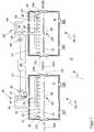
Die Vorrichtung
Zum Transport und zur Lagerung des Substrats
Während der thermischen Bearbeitung des Substrats
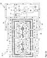
Die Gasverteiler
Die Behandlungskammer
Während aus Gründen der Übersichtlichkeit die Prinzipskizze der
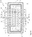
Zusätzlich zur Konvektionsheizung des Substrats
Um die Wärmebehandlungskammer
Zusätzlich bzw. alternativ kann die Wand
Die Vorrichtung
Die Vorrichtung
ZITATE ENTHALTEN IN DER BESCHREIBUNG QUOTES INCLUDE IN THE DESCRIPTION
Diese Liste der vom Anmelder aufgeführten Dokumente wurde automatisiert erzeugt und ist ausschließlich zur besseren Information des Lesers aufgenommen. Die Liste ist nicht Bestandteil der deutschen Patent- bzw. Gebrauchsmusteranmeldung. Das DPMA übernimmt keinerlei Haftung für etwaige Fehler oder Auslassungen.This list of the documents listed by the applicant has been generated automatically and is included solely for the better information of the reader. The list is not part of the German patent or utility model application. The DPMA assumes no liability for any errors or omissions.
Zitierte PatentliteraturCited patent literature
- DE 69812251 T2[0001, 0003, 0004]DE 69812251 T2[0001, 0003, 0004]
Claims (25)
Translated fromGermanPriority Applications (8)
| Application Number | Priority Date | Filing Date | Title |
|---|---|---|---|
| DE102009037299ADE102009037299A1 (en) | 2009-08-14 | 2009-08-14 | Device and treatment chamber for the thermal treatment of substrates |
| PCT/EP2010/004947WO2011018226A1 (en) | 2009-08-14 | 2010-08-12 | Device and treatment chamber for thermally treating substrates |
| KR1020127006094AKR20120050472A (en) | 2009-08-14 | 2010-08-12 | Device and treatment chamber for thermally treating substrates |
| EP10749600.2AEP2464938B1 (en) | 2009-08-14 | 2010-08-12 | Device and treatment chamber for thermally treating substrates |
| US13/386,715US20120171632A1 (en) | 2009-08-14 | 2010-08-12 | Device and treatment chamber for thermally treating substrates |
| JP2012524148AJP2013501908A (en) | 2009-08-14 | 2010-08-12 | Apparatus and processing chamber for thermally processing a substrate |
| CN2010800358990ACN102612631A (en) | 2009-08-14 | 2010-08-12 | Device and treatment chamber for thermally treating substrates |
| TW099127229ATW201116492A (en) | 2009-08-14 | 2010-08-16 | Device and treatment chamber for thermal treatment of substrates |
Applications Claiming Priority (1)
| Application Number | Priority Date | Filing Date | Title |
|---|---|---|---|
| DE102009037299ADE102009037299A1 (en) | 2009-08-14 | 2009-08-14 | Device and treatment chamber for the thermal treatment of substrates |
Publications (1)
| Publication Number | Publication Date |
|---|---|
| DE102009037299A1true DE102009037299A1 (en) | 2011-08-04 |
Family
ID=42983409
Family Applications (1)
| Application Number | Title | Priority Date | Filing Date |
|---|---|---|---|
| DE102009037299AWithdrawnDE102009037299A1 (en) | 2009-08-14 | 2009-08-14 | Device and treatment chamber for the thermal treatment of substrates |
Country Status (8)
| Country | Link |
|---|---|
| US (1) | US20120171632A1 (en) |
| EP (1) | EP2464938B1 (en) |
| JP (1) | JP2013501908A (en) |
| KR (1) | KR20120050472A (en) |
| CN (1) | CN102612631A (en) |
| DE (1) | DE102009037299A1 (en) |
| TW (1) | TW201116492A (en) |
| WO (1) | WO2011018226A1 (en) |
Cited By (8)
| Publication number | Priority date | Publication date | Assignee | Title |
|---|---|---|---|---|
| US20140287373A1 (en)* | 2011-10-26 | 2014-09-25 | Smit Ovens B.V. | Device for heating a substrate |
| EP2876674A1 (en) | 2013-11-25 | 2015-05-27 | Roth & Rau AG | Apparatus for the recovery of inert gas from lock chambers |
| WO2018206617A1 (en)* | 2017-05-11 | 2018-11-15 | Ebner Industrieofenbau Gmbh | Oven system with hot air heating |
| WO2019138134A1 (en)* | 2018-01-15 | 2019-07-18 | Ebner Industrieofenbau Gmbh | Convection furnace |
| DE102023212013A1 (en)* | 2023-11-30 | 2024-12-19 | Carl Zeiss Smt Gmbh | CLEANING CHAMBER AND METHOD FOR CLEANING COMPONENTS, IN PARTICULAR COMPONENTS OF PROJECTION EXPOSURE SYSTEMS, USING THE CLEANING CHAMBER |
| DE102023117945A1 (en) | 2023-07-07 | 2025-01-09 | Singulus Technologies Aktiengesellschaft | lock chamber |
| DE102023119485A1 (en)* | 2023-07-24 | 2025-01-30 | VON ARDENNE Asset GmbH & Co. KG | convection cooling device, cooling chamber and process arrangement |
| WO2025021259A1 (en)* | 2023-07-24 | 2025-01-30 | VON ARDENNE Asset GmbH & Co. KG | Convection cooling device, cooling chamber and process arrangement |
Families Citing this family (29)
| Publication number | Priority date | Publication date | Assignee | Title |
|---|---|---|---|---|
| US9915475B2 (en)* | 2011-04-12 | 2018-03-13 | Jiaxiong Wang | Assembled reactor for fabrications of thin film solar cell absorbers through roll-to-roll processes |
| FR2975223B1 (en)* | 2011-05-10 | 2016-12-23 | Electricite De France | THERMAL TREATMENT BY INJECTION OF A CALOPORANT GAS. |
| US8618446B2 (en)* | 2011-06-30 | 2013-12-31 | Applied Materials, Inc. | Substrate support with substrate heater and symmetric RF return |
| WO2013029197A1 (en)* | 2011-08-29 | 2013-03-07 | 上海北玻玻璃技术工业有限公司 | Inlet and outlet wind heat exchange system for radiation-type heating furnace |
| DE102012100927A1 (en)* | 2012-02-06 | 2013-08-08 | Roth & Rau Ag | process module |
| CN103373806B (en)* | 2012-04-26 | 2017-01-25 | 北京物华天宝镀膜科技有限公司 | Convection heating system of toughening furnace |
| TWI481058B (en)* | 2012-05-24 | 2015-04-11 | Sunshine Pv Corp | Annealing device for a thin-film solar cell |
| TWI474497B (en)* | 2012-05-24 | 2015-02-21 | Sunshine Pv Corp | Annealing device for a thin-film solar cell |
| US20150165475A1 (en)* | 2012-07-09 | 2015-06-18 | Saint-Gobain Glass France | Process box, assembly, and method for processing a coated substrate |
| JP6116685B2 (en)* | 2012-07-09 | 2017-04-19 | サン−ゴバン グラス フランスSaint−Gobain Glass France | Apparatus and method for heat treating an object |
| BE1024010B1 (en)* | 2012-09-21 | 2017-10-27 | Agc Glass Europe | BOMBAGE OF GLAZING |
| KR101399663B1 (en)* | 2012-10-04 | 2014-05-30 | 주식회사 테라세미콘 | Heat treatment apparatus |
| CN103839875B (en)* | 2012-11-21 | 2017-08-22 | 北京北方微电子基地设备工艺研究中心有限责任公司 | A kind of lining treatment system |
| KR101328160B1 (en)* | 2013-02-18 | 2013-11-13 | 장근수 | Heating apparatus |
| CN103322796B (en)* | 2013-05-23 | 2015-03-11 | 江阴江顺铝型材成套设备制造有限公司 | Energy-saving type multiple long rod hot-shearing furnace |
| GB201317170D0 (en)* | 2013-09-27 | 2013-11-06 | Ebner Ind Ofenbau | Furnace with a convection and radiation heating |
| GB201317194D0 (en)* | 2013-09-27 | 2013-11-13 | Ebner Ind Ofenbau | |
| CN104681402B (en)* | 2015-03-16 | 2018-03-16 | 京东方科技集团股份有限公司 | Substrate heating equipment and substrate heating method |
| US20190055152A1 (en)* | 2016-01-28 | 2019-02-21 | Corning Incorporated | Apparatuses for thermally tempering glass using liquid conduction |
| DE102016110677B4 (en)* | 2016-06-09 | 2018-07-12 | Ebner Industrieofenbau Gmbh | Temperature control device for components |
| JP6837929B2 (en)* | 2017-06-23 | 2021-03-03 | 東京エレクトロン株式会社 | Board processing equipment |
| CN108267015A (en)* | 2017-12-29 | 2018-07-10 | 广州泰行智能科技有限公司 | Heat dissipating method, device, terminal device and the storage medium of silk-screen continuous tunnel furnace |
| WO2020052828A1 (en) | 2018-09-14 | 2020-03-19 | Saint-Gobain Glass France | Device and method for thermally tempering glass panes with heat exchanger |
| CN109585598A (en)* | 2018-11-13 | 2019-04-05 | 横店集团东磁股份有限公司 | The bad order ameliorative way of cell piece |
| TWI765571B (en)* | 2021-02-09 | 2022-05-21 | 華邦電子股份有限公司 | Hot plate cooling system |
| CN115116882B (en)* | 2021-03-17 | 2025-08-12 | 华邦电子股份有限公司 | Hot plate cooling system |
| FR3147271A1 (en)* | 2023-03-31 | 2024-10-04 | Saint-Gobain Glass France | Glass furnace |
| FI131326B1 (en)* | 2023-08-16 | 2025-02-20 | Glaston Finland Oy | Tempering furnace and method for assembling tempering furnace |
| CN117410213B (en)* | 2023-12-13 | 2024-03-22 | 浙江果纳半导体技术有限公司 | Wafer transmission device |
Citations (12)
| Publication number | Priority date | Publication date | Assignee | Title |
|---|---|---|---|---|
| DE660539C (en)* | 1936-09-30 | 1938-05-28 | Curt Richter | Device for quenching glass objects |
| DE811269C (en)* | 1947-08-29 | 1951-08-20 | Emile Bernard | Facility for the production of tempered glass |
| GB1028652A (en)* | 1962-02-07 | 1966-05-04 | Pilkington Brothers Ltd | Improvements in or relating to furnaces |
| DE3715151A1 (en)* | 1987-05-07 | 1988-11-17 | Ver Glaswerke Gmbh | METHOD AND DEVICES FOR BENDING GLASS PANES |
| US4853019A (en)* | 1982-10-11 | 1989-08-01 | Saint Gobain Vitrage | Method for the transportation of glass sheets brought to the deformation temperature, its application to bending and device for its implementation |
| DE4115235C1 (en)* | 1991-05-10 | 1992-12-24 | Vegla Vereinigte Glaswerke Gmbh, 5100 Aachen, De | |
| EP0581742A1 (en)* | 1992-07-31 | 1994-02-02 | POPPI S.p.A. | A plant for tempering, in particular sheets of glass and the like |
| EP0649821A1 (en)* | 1993-10-25 | 1995-04-26 | Cattin Machines S.A. | Apparatus for heating or cooling of flat glass sheets or strips |
| EP0662455A2 (en)* | 1994-01-11 | 1995-07-12 | Rastal GmbH & Co. KG | Method for increasing the resistance of glass bodies and apparatus therefor |
| DE19520341A1 (en)* | 1995-06-02 | 1996-12-05 | Bosch Siemens Hausgeraete | Oven with heat-insulated chamber |
| DE69812251T2 (en) | 1997-08-15 | 2003-11-13 | Tamglass Ltd. Oy, Tampere | Semi-convectively forced air system and method for heating glass with low emissivity |
| US20070220921A1 (en)* | 2004-05-27 | 2007-09-27 | Yan Zhao | Glass Heating Furnance with Opposing Gas Streams |
Family Cites Families (13)
| Publication number | Priority date | Publication date | Assignee | Title |
|---|---|---|---|---|
| NL132487C (en)* | 1962-11-19 | |||
| FI76315C (en)* | 1986-10-29 | 1988-10-10 | Kyro Oy | ANIMAL CONDITIONING FOR GLASS MEASUREMENT. |
| US6046439A (en)* | 1996-06-17 | 2000-04-04 | Mattson Technology, Inc. | System and method for thermal processing of a semiconductor substrate |
| US6131411A (en)* | 1998-12-21 | 2000-10-17 | Glasstech, Inc. | Method and furnace for heating glass sheets |
| JP4268303B2 (en)* | 2000-02-01 | 2009-05-27 | キヤノンアネルバ株式会社 | Inline type substrate processing equipment |
| JP4537312B2 (en)* | 2001-02-23 | 2010-09-01 | 株式会社タムラ製作所 | Hot air jet type heating device and heating furnace |
| US7290405B2 (en)* | 2001-07-11 | 2007-11-06 | Feracitas Oy | Method and apparatus for conducting heat to a glass sheet |
| US8328551B2 (en)* | 2002-09-26 | 2012-12-11 | Btu International, Inc. | Convection furnace thermal profile enhancement |
| FI120451B (en)* | 2003-06-24 | 2009-10-30 | Uniglass Engineering Oy | Method and apparatus for heating glass |
| DE102005033776B4 (en)* | 2005-07-15 | 2007-06-21 | Eliog-Kelvitherm Industrieofenbau Gmbh | Flat glass furnace |
| US8153513B2 (en)* | 2006-07-25 | 2012-04-10 | Silicon Genesis Corporation | Method and system for continuous large-area scanning implantation process |
| JP4357517B2 (en)* | 2006-10-16 | 2009-11-04 | 株式会社東芝 | Nanocarbon generator |
| US8069817B2 (en)* | 2007-03-30 | 2011-12-06 | Lam Research Corporation | Showerhead electrodes and showerhead electrode assemblies having low-particle performance for semiconductor material processing apparatuses |
- 2009
- 2009-08-14DEDE102009037299Apatent/DE102009037299A1/ennot_activeWithdrawn
- 2010
- 2010-08-12WOPCT/EP2010/004947patent/WO2011018226A1/enactiveApplication Filing
- 2010-08-12CNCN2010800358990Apatent/CN102612631A/enactivePending
- 2010-08-12JPJP2012524148Apatent/JP2013501908A/enactivePending
- 2010-08-12KRKR1020127006094Apatent/KR20120050472A/ennot_activeWithdrawn
- 2010-08-12USUS13/386,715patent/US20120171632A1/ennot_activeAbandoned
- 2010-08-12EPEP10749600.2Apatent/EP2464938B1/ennot_activeNot-in-force
- 2010-08-16TWTW099127229Apatent/TW201116492A/enunknown
Patent Citations (12)
| Publication number | Priority date | Publication date | Assignee | Title |
|---|---|---|---|---|
| DE660539C (en)* | 1936-09-30 | 1938-05-28 | Curt Richter | Device for quenching glass objects |
| DE811269C (en)* | 1947-08-29 | 1951-08-20 | Emile Bernard | Facility for the production of tempered glass |
| GB1028652A (en)* | 1962-02-07 | 1966-05-04 | Pilkington Brothers Ltd | Improvements in or relating to furnaces |
| US4853019A (en)* | 1982-10-11 | 1989-08-01 | Saint Gobain Vitrage | Method for the transportation of glass sheets brought to the deformation temperature, its application to bending and device for its implementation |
| DE3715151A1 (en)* | 1987-05-07 | 1988-11-17 | Ver Glaswerke Gmbh | METHOD AND DEVICES FOR BENDING GLASS PANES |
| DE4115235C1 (en)* | 1991-05-10 | 1992-12-24 | Vegla Vereinigte Glaswerke Gmbh, 5100 Aachen, De | |
| EP0581742A1 (en)* | 1992-07-31 | 1994-02-02 | POPPI S.p.A. | A plant for tempering, in particular sheets of glass and the like |
| EP0649821A1 (en)* | 1993-10-25 | 1995-04-26 | Cattin Machines S.A. | Apparatus for heating or cooling of flat glass sheets or strips |
| EP0662455A2 (en)* | 1994-01-11 | 1995-07-12 | Rastal GmbH & Co. KG | Method for increasing the resistance of glass bodies and apparatus therefor |
| DE19520341A1 (en)* | 1995-06-02 | 1996-12-05 | Bosch Siemens Hausgeraete | Oven with heat-insulated chamber |
| DE69812251T2 (en) | 1997-08-15 | 2003-11-13 | Tamglass Ltd. Oy, Tampere | Semi-convectively forced air system and method for heating glass with low emissivity |
| US20070220921A1 (en)* | 2004-05-27 | 2007-09-27 | Yan Zhao | Glass Heating Furnance with Opposing Gas Streams |
Cited By (12)
| Publication number | Priority date | Publication date | Assignee | Title |
|---|---|---|---|---|
| US20140287373A1 (en)* | 2011-10-26 | 2014-09-25 | Smit Ovens B.V. | Device for heating a substrate |
| US10014433B2 (en)* | 2011-10-26 | 2018-07-03 | Smit Thermal Solutions B.V. | Device for heating a substrate |
| EP2876674A1 (en) | 2013-11-25 | 2015-05-27 | Roth & Rau AG | Apparatus for the recovery of inert gas from lock chambers |
| WO2018206617A1 (en)* | 2017-05-11 | 2018-11-15 | Ebner Industrieofenbau Gmbh | Oven system with hot air heating |
| AT522006A5 (en)* | 2017-05-11 | 2020-07-15 | Ebner Ind Ofenbau | Oven system with hot air heating |
| WO2019138134A1 (en)* | 2018-01-15 | 2019-07-18 | Ebner Industrieofenbau Gmbh | Convection furnace |
| US11598580B2 (en) | 2018-01-15 | 2023-03-07 | Ebner Industrieofenbau Gmbh | Convection furnace |
| DE102023117945A1 (en) | 2023-07-07 | 2025-01-09 | Singulus Technologies Aktiengesellschaft | lock chamber |
| WO2025012040A1 (en) | 2023-07-07 | 2025-01-16 | Singulus Technologies Ag | Lock chamber |
| DE102023119485A1 (en)* | 2023-07-24 | 2025-01-30 | VON ARDENNE Asset GmbH & Co. KG | convection cooling device, cooling chamber and process arrangement |
| WO2025021259A1 (en)* | 2023-07-24 | 2025-01-30 | VON ARDENNE Asset GmbH & Co. KG | Convection cooling device, cooling chamber and process arrangement |
| DE102023212013A1 (en)* | 2023-11-30 | 2024-12-19 | Carl Zeiss Smt Gmbh | CLEANING CHAMBER AND METHOD FOR CLEANING COMPONENTS, IN PARTICULAR COMPONENTS OF PROJECTION EXPOSURE SYSTEMS, USING THE CLEANING CHAMBER |
Also Published As
| Publication number | Publication date |
|---|---|
| JP2013501908A (en) | 2013-01-17 |
| KR20120050472A (en) | 2012-05-18 |
| EP2464938A1 (en) | 2012-06-20 |
| TW201116492A (en) | 2011-05-16 |
| CN102612631A (en) | 2012-07-25 |
| EP2464938B1 (en) | 2013-07-31 |
| US20120171632A1 (en) | 2012-07-05 |
| WO2011018226A1 (en) | 2011-02-17 |
Similar Documents
| Publication | Publication Date | Title |
|---|---|---|
| EP2464938B1 (en) | Device and treatment chamber for thermally treating substrates | |
| EP2291868B1 (en) | Device and method for tempering objects in a treatment chamber | |
| DE102006047472A1 (en) | Procedure for the surface treatment of laminar substrates, comprises separating thin function layers from the substrates made of different materials, and carrying out thermal finishing treatment of separated layers on the substrate | |
| EP2609617B1 (en) | Device and method for heat-treating a plurality of multi-layer bodies | |
| EP1277238B1 (en) | Device and method for simultaneous tempering of several process goods | |
| EP2870625B1 (en) | Assembly and method for processing substrates | |
| EP1277237B1 (en) | Device and method for tempering at least one process good | |
| DE102009011495B4 (en) | Method and apparatus for treating substrates using gas separation | |
| DE102010061633A1 (en) | Cooling system and method for a vapor deposition system | |
| EP2739766A1 (en) | Device and method for producing thin films | |
| DE102011056906A1 (en) | A vapor deposition apparatus and method for continuously depositing a thin film layer on a substrate | |
| EP2815426B1 (en) | Process box, process holder, assemblies and method for processing coated substrates | |
| DE102009053532B4 (en) | Method and apparatus for producing a compound semiconductor layer | |
| DE102010002839A1 (en) | Coating semiconductor wafer in coating system, comprises coating the wafers within functional area, and placing individual wafers in two rows next to each other and in two rows one behind other directly on conveyor belt of transport device | |
| DE102010048043A1 (en) | Apparatus and method for processing wafers | |
| DE102008030677B4 (en) | Method and device for the diffusion treatment of workpieces | |
| WO2014009388A1 (en) | Device and method for heat treating an object | |
| DE102013113866B4 (en) | Arrangement for the thermal processing of substrates | |
| DE112017006821T5 (en) | SUBSTRATE PROCESSING DEVICE AND SUBSTRATE MANUFACTURING METHOD | |
| DE102012224500A1 (en) | Diffusion chamber, useful for thermal treatment of substrate of copper indium gallium selenide thin film solar cell, comprises vacuum chamber, and two half-shells arranged within vacuum chamber | |
| DE10141142B4 (en) | Device for reactive plasma treatment of substrates and method for use | |
| DE102015009861A1 (en) | Substrate processing device and coating method | |
| DE102023117945A1 (en) | lock chamber | |
| DE10335460B4 (en) | Method for operating a CVD system | |
| DE102010043799B4 (en) | Quick cooling process for vacuum process plants |
Legal Events
| Date | Code | Title | Description |
|---|---|---|---|
| R119 | Application deemed withdrawn, or ip right lapsed, due to non-payment of renewal fee | ||
| R119 | Application deemed withdrawn, or ip right lapsed, due to non-payment of renewal fee | Effective date:20150303 |