DE102009028582A1 - Electronically commutated electric motor with a rotor position prediction and an interpolation and method - Google Patents
Electronically commutated electric motor with a rotor position prediction and an interpolation and methodDownload PDFInfo
- Publication number
- DE102009028582A1 DE102009028582A1DE102009028582ADE102009028582ADE102009028582A1DE 102009028582 A1DE102009028582 A1DE 102009028582A1DE 102009028582 ADE102009028582 ADE 102009028582ADE 102009028582 ADE102009028582 ADE 102009028582ADE 102009028582 A1DE102009028582 A1DE 102009028582A1
- Authority
- DE
- Germany
- Prior art keywords
- rotor position
- position signal
- rotor
- digital
- electric motor
- Prior art date
- Legal status (The legal status is an assumption and is not a legal conclusion. Google has not performed a legal analysis and makes no representation as to the accuracy of the status listed.)
- Withdrawn
Links
Images


Classifications
- H—ELECTRICITY
- H02—GENERATION; CONVERSION OR DISTRIBUTION OF ELECTRIC POWER
- H02P—CONTROL OR REGULATION OF ELECTRIC MOTORS, ELECTRIC GENERATORS OR DYNAMO-ELECTRIC CONVERTERS; CONTROLLING TRANSFORMERS, REACTORS OR CHOKE COILS
- H02P6/00—Arrangements for controlling synchronous motors or other dynamo-electric motors using electronic commutation dependent on the rotor position; Electronic commutators therefor
- H02P6/14—Electronic commutators
- H02P6/16—Circuit arrangements for detecting position
Landscapes
- Engineering & Computer Science (AREA)
- Power Engineering (AREA)
- Control Of Motors That Do Not Use Commutators (AREA)
Abstract
Translated fromGermanDescription
Translated fromGermanDieErfindung betrifft einen elektronisch kommutierten Elektromotor.Der elektronisch kommutierte Elektromotor weist einen Stator undeinen insbesondere permanentmagnetisch ausgebildeten Rotor auf.Der Elektromotor weist auch eine Steuereinheit auf, welche mit demStator wirkverbunden und ausgebildet ist, Steuersignale zum Kommutierendes Stators derart zu erzeugen, dass der Stator ein magnetischesDrehfeld zum Drehbewegen des Rotors erzeugen kann. Der Elektromotorweist auch wenigstens einen Rotorpositionssensor auf, welcher ausgebildetist, eine Rotorposition, insbesondere eine Winkelposition, des Rotorszu erfassen und ein die Rotorposition repräsentierendesRotorpositionssignal zu erzeugen. Die Steuereinheit ist ausgebildet,die Steuersignale in Abhängigkeit von dem Rotorpositionssignalzu erzeugen.TheThe invention relates to an electronically commutated electric motor.The electronically commutated electric motor has a stator anda particular permanent magnetic trained rotor.The electric motor also has a control unit, which with theStator is operatively connected and formed, control signals for commutationof the stator to produce such that the stator is a magneticRotary field for rotating the rotor can produce. The electric motoralso has at least one rotor position sensor, which is formedis a rotor position, in particular an angular position of the rotorto capture and a rotor position representingTo generate rotor position signal. The control unit is designedthe control signals in response to the rotor position signalto create.
Ausder
Beischnell drehenden elektronisch kommutierten Elektromotoren bestehtdas Problem, dass während eines Betriebes des Elektromotorsdie Rotorpositionserfassung mit einer hohen Erfassungsfrequenz durchgeführtwerden muss, wenn während einer Rotorumdrehung ein häufigerWechsel eines Kommutierungsmusters erfolgen soll. Die Steuereinheitdes Elektromotors muss dann dazu eine entsprechend hohe Rechenkapazitätaufweisen.atfast-rotating electronically commutated electric motorsthe problem that during operation of the electric motorthe rotor position detection is performed at a high detection frequencymust be if more frequent during a rotor rotationChange a Kommutierungsmusters to take place. The control unitThe electric motor must then have a correspondingly high computing capacityexhibit.
Erfindungsgemäß istdie Steuereinheit des elektronisch kommutierten Elektromotors dereingangsgenannten Art ausgebildet, das Rotorpositionssignal abzutastenund zu quantisieren, und ein digitales Rotorpositionssignal zu erzeugen.Das digitale Rotorpositionssignal bildet einen zeitlichen Datenstrom,welcher dem abgetasteten und quantisierten Rotorpositionssignalentspricht, wobei die Steuereinheit einen Interpolator aufweist,welcher ausgebildet ist, wenigstens einen zwischen zwei zeitlichaufeinanderfolgenden Rotorpositionswerten liegenden Zwischenwertin dem digitalen Rotorpositionssignal zu erzeugen. Durch den Interpolatorkann eine Abtastfrequenz eines das insbesondere analoge Rotorpositionssignalabtastenden und quantisierenden Analog-Digital-Wandlers vorteilhaftkleiner sein als ohne den Interpolator. dadurch kann eine Rechenleistung derSteuereinheit, welche beispielsweise durch ein FPGA oder ein ASICgebildet ist, vorteilhaft kleiner sein als ohne den Interpolator.According to the inventionthe control unit of the electronically commutated electric motor offormed the aforementioned type, to sample the rotor position signaland to quantize and generate a digital rotor position signal.The digital rotor position signal forms a temporal data stream,which is the sampled and quantized rotor position signalcorresponds, wherein the control unit has an interpolator,which is formed, at least one between two timessuccessive rotor position values lying intermediate valuein the digital rotor position signal. Through the interpolatormay be a sampling frequency of a particular analog rotor position signalsampling and quantizing analog-to-digital converter advantageousbe smaller than without the interpolator. This can be a computing power ofControl unit, which for example by an FPGA or an ASICis formed, advantageously smaller than without the interpolator.
Weiterbevorzugt ist die Steuereinheit ausgebildet, das digitale Rotorpositionssignalals digitales Prädiktions-Rotorpositionssignal zu erzeugen,wobei das digitale Prädiktions-Rotorpositionssignal, insbesondereder zeitliche Datenstrom, wenigstens einen oder eine Mehrzahl vonzukünftigen, über das Rotorpositionssignal zeitlichhinausführende Rotorpositionswerte umfasst. Bevorzugt istder Interpolator ausgebildet, den Zwischenwert zwischen zwei zukünftigenRotorpositionswerten zu erzeugen. Durch das so gebildete Prädiktions-Rotorpositionssignalkann vorteilhaft die Rotorposition für eine aktuelle Rotorposition,oder für zukünftige Rotorpositionen zum Kommutierendes Elektromotors zur Verfügung stehen. Weiter vorteilhaftkann die so vorausgesagte Rotorposition zum Kommutieren des Elektromotorszur Verfügung stehen, bevor der Rotorpositionssensor, insbesondereein Winkelsensor, nach Wandlung eines beispielsweise analogen Rotorpositionssignalsin ein digitales Rotorpositionssignal, das so gewandelte Rotorpositionssignalzur weiteren Signalverarbeitung zur Verfügung stellen kann.FurtherPreferably, the control unit is designed, the digital rotor position signalas a digital prediction rotor position signal,wherein the digital prediction rotor position signal, in particularthe temporal data stream, at least one or a plurality offuture, via the rotor position signal in timeoutgoing rotor position values. Is preferredthe interpolator formed the intermediate value between two future onesTo generate rotor position values. By the thus formed prediction rotor position signalcan advantageously the rotor position for a current rotor position,or for future rotor positions for commutationof the electric motor are available. Further advantageouscan the so predicted rotor position for commutation of the electric motorare available before the rotor position sensor, in particularan angle sensor, after conversion of an example analog rotor position signalin a digital rotor position signal, the thus converted rotor position signalcan provide for further signal processing.
DerRotorpositionssensor ist bevorzugt ein Winkelsensor. Der Winkelsensorist beispielsweise ein Giant-Magneto-Resisistiver-Sensor (GMR-Sensor)oder ein Anisotroper-Magneto-Resisitiver-Sensor (AMR-Sensor). Ineiner anderen Ausführungsform weist der Elektromotor beispielsweiseeine Mehrzahl von Hall-Sensoren auf, welche jeweils ausgebildetsind, ein insbesondere analoges Rotorpositionssignal zu erzeugen.Bevorzugt ist der Winkelsensor, insbesondere der GMR-Sensor oder AMR-Sensor,ausgebildet, ein zeitkontinuierliches, bevorzugt zeitkontinuierlicheine absolute Rotorposition repräsentierendes, insbesondereanaloges Rotorpositionssignal zu erzeugen. Eine Winkelauflösungdes Winkelsensors ist dann durch eine Abtastrate eines das analogeRotorpositionssignal analog-zu-digital wandelnden Analog-Digital-Wandlers bestimmt.Of theRotor position sensor is preferably an angle sensor. The angle sensoris for example a Giant Magneto Resistive Sensor (GMR sensor)or an anisotropic magnetoresistive sensor (AMR sensor). InIn another embodiment, the electric motor, for examplea plurality of Hall sensors, each of which is formedare to produce a particular analog rotor position signal.Preferably, the angle sensor, in particular the GMR sensor or AMR sensor,formed, a time-continuous, preferably continuous-timean absolute rotor position representing, in particulargenerate analog rotor position signal. An angular resolutionof the angle sensor is then by a sampling rate of the analogRotor position signal analog-to-digital converting analog-to-digital converter determined.
Ineiner bevorzugten Ausführungsform ist die Steuereinheitausgebildet, das insbesondere digitale Prädiktions-Rotorpositionssignalin Abhängigkeit von weiteren, mittels des Rotorpositionssensorserfassten Rotorpositionen insbesondere gemäß einem PrinzipFIFO (FIFO = First-In-First-out) zu korrigieren. Dazu kann das Prädiktions-Rotorpositionssignal beispielsweisedurch eine vorbestimmte Anzahl von Rotorpositionswerten gebildetsein, wobei die Rotorpositionswerte mit jedem neuen von dem Winkelsensorerfassten – weiter bevorzugt zusätzlich von einem Analog-Digitalwandlergewandelten – Rotorpositionswert nach dem Prinzip FIFOaktualisiert werden. Damit kann vorteilhaft die Kommutierung desElektromotors auch mit nicht-stationären Bewegungsmusternerfolgen. Beispielsweise kann die Steuereinheit währendeiner Rotorumdrehung eine Vielzahl zueinander verschiedener Kommutierungsmusterauf den Stator beaufschlagen.InA preferred embodiment is the control unitformed, in particular digital prediction rotor position signalas a function of others, by means of the rotor position sensordetected rotor positions in particular according to a principleCorrect first-in-first-out (FIFO). For this purpose, the prediction rotor position signal, for exampleformed by a predetermined number of rotor position valueswith the rotor position values with each new one from the angle sensorfurther preferably additionally from an analog-to-digital converterconverted - rotor position value according to the FIFO principleto be updated. This can advantageously the commutation of theElectric motor also with non-stationary motion patternsrespectively. For example, the control unit may duringa rotor revolution a variety of mutually different Kommutierungsmusterapply pressure to the stator.
Ineiner bevorzugten Ausführungsform ist die Steuereinheitausgebildet, das digitale Prädiktions-Rotorpositionssignalmittels einer Approximationsfunktion in Abhängigkeit desRotorpositionssignals als zu approximierende Ausgangsfunktion zuerzeugen. Dadurch kann vorteilhaft das mittels des Rotorpositionssensorserzeugte Rotorpositionssignal für zukünftige Rotorpositionenvorteilhaft geschätzt werden.InA preferred embodiment is the control unitformed, the digital prediction rotor position signalby means of an approximation function as a function ofRotor position signal as to be approximated output functionproduce. As a result, advantageously by means of the rotor position sensorgenerated rotor position signal for future rotor positionsbe estimated advantageous.
Bevorzugtist die Approximationsfunktion ein Polynom, insbesondere wenigstenszweiten Grades oder genau zweiten oder dritten Grades. Weitere vorteilhafteAusführungsbeispiele für eine Approximationsfunktionsind eine Spline-Funktion oder eine Exponentialfunktion.Prefersthe approximation function is a polynomial, in particular at leastsecond degree or exactly second or third degree. Further advantageousEmbodiments for an approximation functionare a spline function or an exponential function.
DieSteuereinheit weist in einer vorteilhaften Ausführungsformeinen Zeitgeber auf, und ist ausgebildet, in Abhängigkeiteines von dem Zeitgeber erzeugten Zeitsignals das Prädiktions-Rotorpositionssignalzu erzeugen, wobei eine Taktfrequenz des Zeitgebers größerist als eine Folgefrequenz aufeinander folgender Rotorpositionswertedes digitalen Rotorpositionssignals, und den Stator in Abhängigkeitdes Prädiktions-Rotorpositionssignals zu kommutieren. Dadurchkann der Stator vorteilhaft in Abhängigkeit von Interpolationswertendes Prädiktions-Rotorpositionssignals kommutiert werden.TheControl unit has in an advantageous embodimenta timer, and is trained, dependinga time signal generated by the timer, the prediction rotor position signalto generate, with a clock frequency of the timer largeris as a repetition frequency of successive rotor position valuesthe digital rotor position signal, and the stator in dependenceto commutate the prediction rotor position signal. TherebyFor example, the stator can be advantageous depending on interpolation valuesof the prediction rotor position signal are commutated.
Bevorzugtkann die Steuereinheit dazu ausgebildet sein, den Kommutierungszeitpunktzu einem bevorzugt zukünftigen Rotorpositionswert des Prädiktions-Rotorpositionssignalszu ermitteln, und weiter bevorzugt den Stator an einem zukünftigenRotorpositionswert zu kommutieren.PrefersFor example, the control unit can be designed to control the commutation timeto a preferably future rotor position value of the prediction rotor position signalto determine and further prefers the stator at a futureRotor position value to commutate.
DieErfindung betrifft auch ein Verfahren zum Betreiben eines elektronischkommutierten Elektromotors, insbesondere des zuvor beschriebenen Elektromotors.Bei dem Verfahren wird mittels eines Rotorpositionssensors eineRotorposition erfasst und ein der Rotorposition entsprechendes Rotorpositionssignalerzeugt. Weiter wird bei dem Verfahren bevorzugt das Rotorpositionssignalabgetastet und quantisiert, und ein insbesondere digitales, einen zeitlichenDatenstrom bildendes Prädiktions-Rotorpositionssignal erzeugt.Das Prädiktions-Rotorpositionssignal repräsentiertdas abgetastete und quantisierte Rotorpositionssignal und umfasstwenigstens einen, oder eine Mehrzahl von zukünftigen, überdas Rotorpositionssignal zeitlich hinausreichende Rotorpositionswerte.TheThe invention also relates to a method for operating an electroniccommutated electric motor, in particular of the electric motor described above.In the method, by means of a rotor position sensorRotor position detected and a rotor position corresponding rotor position signalgenerated. Furthermore, in the method, the rotor position signal is preferredsampled and quantized, and a particular digital, a temporalData stream forming prediction rotor position signal generated.The prediction rotor position signal representsthe sampled and quantized rotor position signal andat least one, or a plurality of future, overthe rotor position signal temporally reaching rotor position values.
Ineiner bevorzugten Ausführungsform des Verfahrens wird dasdigitale Prädiktions-Rotorpositionssignal in Abhängigkeitvon weiteren, mittels des Rotorpositionssensors erfassten Rotorpositionen korrigiert.InA preferred embodiment of the method is thedigital prediction rotor position signal in dependencecorrected by further, detected by the rotor position sensor rotor positions.
Ineiner vorteilhaften Ausführungsvariante des Verfahrenswird das digitale Prädiktions-Rotorpositionssignal durchBilden einer Approximationsfunktion in Abhängigkeit desRotorpositionssignals als Ausgangsfunktion erzeugt. Die Ausgangsfunktion istdabei die zu approximierende Funktion, welche Stützstellenzum Erzeugen der Approximationsfunktion bilden kann. Dadurch kanndas Prädiktions-Rotorpositionssignal auch übereinen durch die Stützstellen gebildeten – beispielsweisemittels des Rotorpositionssignals gebildeten, oder aus diesem erzeugten – Bereichhinaus extrapoliert sein. Die Approximationsfunktion ist bevorzugteine Polynomfunktion zweiten oder dritten Grades.Inan advantageous embodiment of the methodthe digital prediction rotor position signal is passed throughForming an approximation function as a function ofRotor position signal generated as an output function. The output function iswhile the function to be approximated, which support pointsto generate the approximation function. This canthe prediction rotor position signal also overone formed by the support points - for exampleformed by the rotor position signal, or generated from this - areaBe extrapolated. The approximation function is preferreda second or third degree polynomial function.
Ineiner bevorzugten Ausführungsform des Verfahrens erfolgtin Abhängigkeit des Prädiktions-Rotorpositionssignalsnach Ablauf eines Zeitintervalls ein Kommutieren des Stators, wobeider Ablauf einem vorbestimmten Kommutierungszeitpunkt entspricht.Bevorzugt erfolgt das Kommutieren mittels wenigstens eines, bevorzugtvorbestimmten, Kommutierungsmusters. Dadurch kann das Kommutierenvorteilhaft bereits vor einem Vorliegen eines mittels des Rotorpositionssensorserzeugten Rotorpositionswertes erfolgen.Ina preferred embodiment of the method takes placedepending on the prediction rotor position signalafter a time interval, commutation of the stator, whereinthe sequence corresponds to a predetermined commutation time.Preferably, the commutation is carried out by means of at least one, preferablypredetermined commutation pattern. This can cause the commutationadvantageously already before the presence of one by means of the rotor position sensorgenerated rotor position value done.
Beidem Verfahren erfolgt ein Ermitteln des zukünftigen Rotorpositionswertesin Abhängigkeit der Approximationsfunktion, beispielsweisedes Polynoms, der Splinefunktion oder einer anderen geeigneten Approximationsfunktion.Die dazu notwendigen Multiplikationen können vorteilhaftdurch eine entsprechend schnelle Recheneinheit erfolgen.atthe method is determined by determining the future rotor position valuedepending on the approximation function, for exampleof the polynomial, the spline function or another suitable approximation function.The multiplications necessary for this can be advantageousdone by a correspondingly fast arithmetic unit.
DieSteuereinheit kann beispielsweise ein Mikroprozessor, ein Mikrocontrolleroder ein FPGA (FPGA = Field-Programmable-Gate-Array), oder ein ASIC(ASIC = Application-Specific-Integrated-Circuit) sein. Die Steuereinheitwird beispielsweise durch ein Steuerprogramm gesteuert, welchesauf einem Datenträger gespeichert ist und zusammen mit demDatenträger ein Computer-Programmprodukt bildet.TheControl unit may for example be a microprocessor, a microcontrolleror an FPGA (FPGA = Field Programmable Gate Array), or an ASIC(ASIC = Application-Specific-Integrated-Circuit). The control unitis controlled, for example, by a control program whichis stored on a disk and together with theDisk forms a computer program product.
DieErfindung betrifft auch eine Steuereinheit gemäß dervorbeschriebenen Art für einen Elektromotor der vorbeschriebenenArt. Die Steuereinheit weist dann keinen Rotor und keinen Statorauf und ist ausgebildet, mit einem Stator eines Elektromotors verbundenzu werden.TheThe invention also relates to a control unit according toabove-described type for an electric motor of the aboveArt. The control unit then has no rotor and no statoron and is formed connected to a stator of an electric motorto become.
DieErfindung wird nun im Folgenden anhand von Figuren und weiterenAusführungsbeispielen beschrieben. Weitere vorteilhafteAusführungsvarianten ergeben sich aus den zuvor beschriebenenMerkmalen, sowie den in der Figurenbeschreibung angegebenen Merkmalen,und den in den abhängigen Ansprüchen angegebenenMerkmalen.TheInvention will now be described below with reference to figures and othersEmbodiments described. Further advantageousEmbodiment variants result from the previously describedCharacteristics, as well as the features specified in the figure description,and those specified in the dependent claimsFeatures.
DerAnalog-Digitalwandler
DerPolynomerzeuger ist vorzugsweise ausgebildet, die Approximationsfunktionmittels einer Methode des kleinsten Fehlerquadrats zu erzeugen.Of thePolynomial generator is preferably formed, the approximation functionusing a method of least square error.
DieApproximationsfunktion ist bevorzugt ein Polynom, insbesondere einPolynom zweiten oder dritten Grades. Denkbar ist auch – insbesonderein Abhängigkeit einer benötigten Rechenzeit desPolynomerzeugers – ein Polynom mehr als dritten Grades.TheApproximation function is preferably a polynomial, in particular aSecond or third degree polynomial. It is also conceivable - in particulardepending on a required computing time of thePolynomial generator - a polynomial more than third degree.
DerPolynomerzeuger
DieApproximationsfunktion, insbesondere das Polynom, kann beispielsweisewie folgt gebildet sein:
- ye,n(Δn)
- = Prädiktorpolynomals Approximationsfunktion;
- n
- = Abtastwert, ganzeZahl oder Zahl < 1;
- Ta
- = Abtastperiode;
- g
- = Grad des Polynoms;
- a
- = Polynomkoeffizient.
- ye, n (Δn)
- = Predictor polynomial as approximation function;
- n
- = Sample, integer or number <1;
- Ta
- = Sampling period;
- G
- = Degree of the polynomial;
- a
- = Polynomial coefficient.
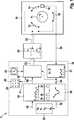
DieSteuereinheit
DieSteuereinheit
DerPolynomerzeuger
DieSteuereinheit
DieSteuereinheit
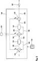
DasDiagramm
Dargestelltsind auch Rotorpositionswerte
DerRotorpositionswert
Dargestelltsind auch ein Zeitintervall
DieRotorpositionswerte
DerRotorpositionswert
DerSteuereinheit – beispielsweise der Steuereinheit
Durchdas Erzeugen des Prädiktorpolynoms und das Vorhersagender zukünftigen Rotorpositionswerte, welche von dem Winkelsensornoch nicht erfasst worden sind, kann vorteilhaft eine Abtastfrequenzzum Erfassen einer Rotorposition des Rotors niedriger sein, alsohne die Vorhersage mittels des Prädiktor-Polynoms. Weitervorteilhaft wird die niedrige Abtastfrequenz des Abtastens des Rotorpositionssignals.durch das Erzeugen der Zwischenwerte mittels Interpolation kompensiertoder verbessert.Bygenerating the predictor polynomial and predictingthe future rotor position values, which of the angle sensorhave not yet been detected, can advantageously a sampling frequencyfor detecting a rotor position of the rotor to be lower thanwithout the prediction by means of the predictor polynomial. Furtheradvantageous is the low sampling frequency of the sampling of the rotor position signal.compensated by generating the intermediate values by means of interpolationor improved.
Wennbeispielsweise die Rotorpositionswerte
Ineinem weiteren Verlauf des Verfahrens zum Kommutieren des Elektromotorskann die Steuereinheit, beispielsweise die Steuereinheit
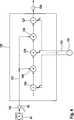
DerMultiplizierer
DerPrädiktor
DerPrädiktor
DerSpeicher
DerAddierer
DiePolynom-Koeffizienten können von dem Polynomerzeuger
- b0,b1, b2,
- taktabhängigePolynomkoeffizienten
- L
- = Vielfaches der AbtastfrequenzTa des Analog-
Digitalwandlers 27 in1
- b0 , b1 , b2 ,
- clock-dependent polynomial coefficients
- L
- = Multiple of the sampling frequency Ta of the analog-to-
digital converter 27 in1
Diemittels des Prädiktors
DieIntegratoren des Prädiktors
- fTakt
- = Taktfrequenz desZeittaktes zum Takten der Integratoren,
- Ta
- = Abtastperiode, beispielsweisedes Analog-
Digitalwandlers 27 in1 - L
- = Faktor, vorteilhaftals Potenz L = 2n
- fbar
- = Clock frequency of the clock for clocking the integrators,
- Ta
- = Sampling period, for example, the analog-to-
digital converter 27 in1 - L
- = Factor, advantageously as power L = 2n
Vorteilhaftist der Faktor L als Potenz zu einer Basis
ZITATE ENTHALTEN IN DER BESCHREIBUNGQUOTES INCLUDE IN THE DESCRIPTION
Diese Listeder vom Anmelder aufgeführten Dokumente wurde automatisierterzeugt und ist ausschließlich zur besseren Informationdes Lesers aufgenommen. Die Liste ist nicht Bestandteil der deutschenPatent- bzw. Gebrauchsmusteranmeldung. Das DPMA übernimmtkeinerlei Haftung für etwaige Fehler oder Auslassungen.This listThe documents listed by the applicant have been automatedgenerated and is solely for better informationrecorded by the reader. The list is not part of the GermanPatent or utility model application. The DPMA takes overno liability for any errors or omissions.
Zitierte PatentliteraturCited patent literature
- - DE 10332381A1[0002]- DE 10332381 A1[0002]
Claims (13)
Translated fromGermanPriority Applications (6)
| Application Number | Priority Date | Filing Date | Title |
|---|---|---|---|
| DE102009028582ADE102009028582A1 (en) | 2009-08-17 | 2009-08-17 | Electronically commutated electric motor with a rotor position prediction and an interpolation and method |
| PCT/EP2010/060832WO2011020682A1 (en) | 2009-08-17 | 2010-07-27 | Electronically commutated electric motor featuring prediction of the rotor position and interpolation, and method |
| EP10734757AEP2467930A1 (en) | 2009-08-17 | 2010-07-27 | Electronically commutated electric motor featuring prediction of the rotor position and interpolation, and method |
| US13/391,076US20120146561A1 (en) | 2009-08-17 | 2010-07-27 | Electronically commutated electric motor featuring prediction of the rotor position and interpolation, and method |
| JP2012525116AJP5479593B2 (en) | 2009-08-17 | 2010-07-27 | Electronic commutation motor and method having rotor position prediction and interpolation functions |
| CN201080036361.1ACN102474211B (en) | 2009-08-17 | 2010-07-27 | Electronically commutated motor and method with rotor position prediction and interpolation |
Applications Claiming Priority (1)
| Application Number | Priority Date | Filing Date | Title |
|---|---|---|---|
| DE102009028582ADE102009028582A1 (en) | 2009-08-17 | 2009-08-17 | Electronically commutated electric motor with a rotor position prediction and an interpolation and method |
Publications (1)
| Publication Number | Publication Date |
|---|---|
| DE102009028582A1true DE102009028582A1 (en) | 2011-02-24 |
Family
ID=42732108
Family Applications (1)
| Application Number | Title | Priority Date | Filing Date |
|---|---|---|---|
| DE102009028582AWithdrawnDE102009028582A1 (en) | 2009-08-17 | 2009-08-17 | Electronically commutated electric motor with a rotor position prediction and an interpolation and method |
Country Status (6)
| Country | Link |
|---|---|
| US (1) | US20120146561A1 (en) |
| EP (1) | EP2467930A1 (en) |
| JP (1) | JP5479593B2 (en) |
| CN (1) | CN102474211B (en) |
| DE (1) | DE102009028582A1 (en) |
| WO (1) | WO2011020682A1 (en) |
Cited By (3)
| Publication number | Priority date | Publication date | Assignee | Title |
|---|---|---|---|---|
| WO2022263039A1 (en)* | 2021-06-15 | 2022-12-22 | Robert Bosch Gmbh | Method for determining a controlling rotational angle of an electric motor |
| DE102022113399A1 (en) | 2022-05-27 | 2023-11-30 | Jörg Heinrich | Device, system and method for determining the position of the rotor of an electrical machine |
| DE102022209630A1 (en) | 2022-09-14 | 2024-03-14 | Robert Bosch Gesellschaft mit beschränkter Haftung | Method and device for providing a speed signal for brush-commutated electric motors |
Families Citing this family (3)
| Publication number | Priority date | Publication date | Assignee | Title |
|---|---|---|---|---|
| US10444714B2 (en) | 2016-06-21 | 2019-10-15 | General Electric Company | Machine monitoring device |
| WO2018073889A1 (en)* | 2016-10-18 | 2018-04-26 | 三菱電機株式会社 | Peak position calculation device and display device |
| CN108871385B (en)* | 2017-05-12 | 2021-09-07 | 西门子公司 | Encoder, motor, encoder data processing method and storage medium |
Citations (1)
| Publication number | Priority date | Publication date | Assignee | Title |
|---|---|---|---|---|
| DE10332381A1 (en) | 2003-07-17 | 2005-02-03 | Ebm-Papst Mulfingen Gmbh & Co. Kg | Method and control system for the electronic commutation of a brushless DC motor |
Family Cites Families (11)
| Publication number | Priority date | Publication date | Assignee | Title |
|---|---|---|---|---|
| EP0801843A1 (en)* | 1994-03-03 | 1997-10-22 | Iomega Corporation | Servo motor controller using position interpolation |
| JP3380254B2 (en)* | 1995-02-07 | 2003-02-24 | 日本信号株式会社 | A device that confirms stoppage of moving parts |
| JP4288851B2 (en)* | 2000-12-27 | 2009-07-01 | パナソニック株式会社 | Motor drive device |
| US6642712B2 (en)* | 2001-04-09 | 2003-11-04 | General Motors Corporation | Device and method for predicting rotational positions of a rotating shaft |
| JP2003022133A (en)* | 2001-07-09 | 2003-01-24 | Yaskawa Electric Corp | Sampling processing method, speed command correction method, and processing means |
| GB0312848D0 (en)* | 2003-06-04 | 2003-07-09 | Switched Reluctance Drives Ltd | Rotor position detection of a switched reluctance drive |
| GB0424367D0 (en)* | 2004-11-03 | 2004-12-08 | Switched Reluctance Drives Ltd | Operation of an electrical machine |
| KR20070118310A (en)* | 2005-05-11 | 2007-12-14 | 도요다 지도샤 가부시끼가이샤 | Angular position detector and rotary electric drive unit with it |
| JP2006343318A (en)* | 2005-05-11 | 2006-12-21 | Toyota Motor Corp | Rotational position detector, and rotary electrical equipment driving unit provided therewith |
| JP4708992B2 (en)* | 2005-12-12 | 2011-06-22 | 日立オートモティブシステムズ株式会社 | Position detecting apparatus and synchronous motor driving apparatus using the same |
| DE602006010024D1 (en)* | 2006-03-24 | 2009-12-10 | Lgl Electronics Spa | Positive yarn delivery device for textile machines, with feedback-controlled synchronous motor |
- 2009
- 2009-08-17DEDE102009028582Apatent/DE102009028582A1/ennot_activeWithdrawn
- 2010
- 2010-07-27CNCN201080036361.1Apatent/CN102474211B/ennot_activeExpired - Fee Related
- 2010-07-27USUS13/391,076patent/US20120146561A1/ennot_activeAbandoned
- 2010-07-27JPJP2012525116Apatent/JP5479593B2/ennot_activeExpired - Fee Related
- 2010-07-27WOPCT/EP2010/060832patent/WO2011020682A1/enactiveApplication Filing
- 2010-07-27EPEP10734757Apatent/EP2467930A1/ennot_activeWithdrawn
Patent Citations (1)
| Publication number | Priority date | Publication date | Assignee | Title |
|---|---|---|---|---|
| DE10332381A1 (en) | 2003-07-17 | 2005-02-03 | Ebm-Papst Mulfingen Gmbh & Co. Kg | Method and control system for the electronic commutation of a brushless DC motor |
Cited By (3)
| Publication number | Priority date | Publication date | Assignee | Title |
|---|---|---|---|---|
| WO2022263039A1 (en)* | 2021-06-15 | 2022-12-22 | Robert Bosch Gmbh | Method for determining a controlling rotational angle of an electric motor |
| DE102022113399A1 (en) | 2022-05-27 | 2023-11-30 | Jörg Heinrich | Device, system and method for determining the position of the rotor of an electrical machine |
| DE102022209630A1 (en) | 2022-09-14 | 2024-03-14 | Robert Bosch Gesellschaft mit beschränkter Haftung | Method and device for providing a speed signal for brush-commutated electric motors |
Also Published As
| Publication number | Publication date |
|---|---|
| CN102474211A (en) | 2012-05-23 |
| JP5479593B2 (en) | 2014-04-23 |
| JP2013502200A (en) | 2013-01-17 |
| US20120146561A1 (en) | 2012-06-14 |
| EP2467930A1 (en) | 2012-06-27 |
| WO2011020682A1 (en) | 2011-02-24 |
| CN102474211B (en) | 2016-01-20 |
Similar Documents
| Publication | Publication Date | Title |
|---|---|---|
| DE102009028582A1 (en) | Electronically commutated electric motor with a rotor position prediction and an interpolation and method | |
| EP2324566B1 (en) | Method and device for processing a motor signal of a dc motor, having current ripples | |
| DE102004046803B4 (en) | Method for determining the angular position of a rotating object and rotary encoder | |
| DE2934739C2 (en) | Digital servo control circuit | |
| EP1391029B1 (en) | Method for determining the rotational position of the drive shaft of a commutated dc motor | |
| DE102015102370A1 (en) | Resolver excitation circuit | |
| DE102009028590A1 (en) | Electronically commutated electric motor with a rotor position prediction and method | |
| EP1390763B1 (en) | Method for correcting the determination of the rotational position of a commutated d.c. motor drive shaft | |
| EP1208639B1 (en) | Method for providing a digital current fluctuation signal | |
| DE102010053955A1 (en) | Data acquisition method for motor car, involves determining data parameters by analysis of raw data, and computing filter parameters, scanning parameters, quantization parameters and/or configuration parameters by data parameters | |
| DE102009008752A1 (en) | Signal shaping using feedback with a finite impulse response | |
| DE19829290A1 (en) | Process for digital clock recovery and selective filtering | |
| DE102010032296B4 (en) | Method for processing a measured value signal representing an analogue value for output current of an inverter and apparatus for carrying out the method | |
| EP0148413B1 (en) | Method and apparatus for reproducing digitized signals, transmitted as digital signals in pulse form | |
| DE102009045822A1 (en) | Electronically commutated electric motor with calibrated motor torque constant | |
| EP0477690B1 (en) | Data reduction method for digital processing a series of signal values | |
| DE69421072T2 (en) | Device for processing servo signals in a parallel hard disk reader | |
| DE102020108928A1 (en) | Device with a sensor, control and corresponding method | |
| DE69524019T2 (en) | Digital signal processing system | |
| DE102008039333A1 (en) | Rotating structure i.e. rotary disk, rotating angle measuring method for e.g. aircraft, involves determining arc tangent of division in analog manner using specific function, where determined arc tangent corresponds to angle of structure | |
| DE102010027471A1 (en) | Method for processing an analog measured value signal, resolver arrangement for carrying out the method and method for determining an output current of an inverter | |
| DE102024206900A1 (en) | Method for converting a data rate and data rate conversion unit | |
| DE3100700C2 (en) | Arrangement for the reconstruction of the time-dependent course of a band-limited analog signal | |
| DE10306127A1 (en) | Determination of direction of an external magnetic field using a magnetoresistive sensor, whereby sensor signals are digitized and decimalized to obtain decimalization factors for 180 and 360 degree periodic signals | |
| DE102015211247A1 (en) | Method and device for processing a signal |
Legal Events
| Date | Code | Title | Description |
|---|---|---|---|
| R012 | Request for examination validly filed | ||
| R119 | Application deemed withdrawn, or ip right lapsed, due to non-payment of renewal fee | ||
| R002 | Refusal decision in examination/registration proceedings |