Movatterモバイル変換


[0]ホーム

URL:


DE102009012273B4 - Optical sensor - Google Patents

Optical sensor
Download PDF

Info

Publication number
DE102009012273B4
DE102009012273B4DE102009012273.7ADE102009012273ADE102009012273B4DE 102009012273 B4DE102009012273 B4DE 102009012273B4DE 102009012273 ADE102009012273 ADE 102009012273ADE 102009012273 B4DE102009012273 B4DE 102009012273B4
Authority
DE
Germany
Prior art keywords
concentrator
transmitter
transmitted light
optical sensor
light rays
Prior art date
Legal status (The legal status is an assumption and is not a legal conclusion. Google has not performed a legal analysis and makes no representation as to the accuracy of the status listed.)
Active
Application number
DE102009012273.7A
Other languages
German (de)
Other versions
DE102009012273A1 (en
Inventor
Nikola Dokman
Jörg Huß
Wolfgang Carrle
Current Assignee (The listed assignees may be inaccurate. Google has not performed a legal analysis and makes no representation or warranty as to the accuracy of the list.)
Leuze Electronic GmbH and Co KG
Original Assignee
Leuze Electronic GmbH and Co KG
Priority date (The priority date is an assumption and is not a legal conclusion. Google has not performed a legal analysis and makes no representation as to the accuracy of the date listed.)
Filing date
Publication date
Priority claimed from DE102008014349Aexternal-prioritypatent/DE102008014349B4/en
Application filed by Leuze Electronic GmbH and Co KGfiledCriticalLeuze Electronic GmbH and Co KG
Priority to DE102009012273.7ApriorityCriticalpatent/DE102009012273B4/en
Priority to EP10001176.6Aprioritypatent/EP2226654B8/en
Priority to CN201010130008.1Aprioritypatent/CN101825764B/en
Publication of DE102009012273A1publicationCriticalpatent/DE102009012273A1/en
Application grantedgrantedCritical
Publication of DE102009012273B4publicationCriticalpatent/DE102009012273B4/en
Activelegal-statusCriticalCurrent
Anticipated expirationlegal-statusCritical

Links

Images

Classifications

Landscapes

Abstract

Translated fromGerman

Optischer Sensor (1) zur Erfassung von Objekten (2) in einem Überwachungsbereich, mit einem Sendelichtstrahlen (4) emittierenden Sender (5), einem Empfangslichtstrahlen (7) empfangenden Empfänger (8), einer Auswerteeinheit (10), in welcher in Abhängigkeit der Empfangssignale am Ausgang des Empfängers (8) ein Objektfeststellungssignal generiert wird, und mit einer dem Sender (5) nachgeordneten Sendeoptik (6) zur Strahlformung der Sendelichtstrahlen (4), wobei die Sendeoptik (6) unmittelbar an den Sender (5) anschließt und einen Konzentrator (15) aufweist, der ein Lichtführungselement für die Sendelichtstrahlen (4) bildet, wobei hierzu an der Mantelfläche (17) des Konzentrators (15) eine Totalreflexion der Sendelichtstrahlen (4) erfolgt, wobei die dem Sender (5) zugeordnete Stirnseite des Konzentrators (15) als Einkoppelfläche (16) für die Sendelichtstrahlen (4) ausgebildet ist, und wobei an der dem Sender (5) abgewandten Stirnseite des Konzentrators (15) eine Austrittsfläche (18) vorgesehen ist, welche ein Strahlformungsmittel für die Sendelichtstrahlen (4) bildet, gemäß DE 10 2008 014 349 B4, dadurch gekennzeichnet, dass die Einkoppelfläche (16) einen trichterförmigen Hohlraum (23) begrenzt, der an der Stirnseite des Konzentrators (15) ausmündet, dass die Einkoppelfläche eine Stirnfläche (16a), deren Normalenvektor mit der Längsachse des Konzentrators (15) zusammen fällt, und ein zur Längsachse des Konzentrators (15) rotationssymmetrisches Mantelflächensegment (16b) aufweist, dass aus dem Sender (5) austretende Sendelichtstrahlen (4), deren Strahlachsen in einem Winkel zur Längsachse des Konzentrators (15) verlaufen, der größer als ein Selektionswinkel ist, über das Mantelflächensegment (16b) aus dem Konzentrator (15) ausgekoppelt und dadurch ausgeblendet werden, und dass das Mantelflächensegment (16b) eine konische Form aufweist.Optical sensor (1) for detecting objects (2) in a monitored area, with a transmitter (5) emitting light beams (4), a receiver (8) receiving light beams (7), an evaluation unit (10) in which, depending on the Received signals at the output of the receiver (8) an object detection signal is generated, and with a transmission optics (6) downstream of the transmitter (5) for beam shaping of the transmitted light beams (4), the transmission optics (6) directly connected to the transmitter (5) and a Has concentrator (15) which forms a light guide element for the transmitted light rays (4), for this purpose a total reflection of the transmitted light rays (4) takes place on the lateral surface (17) of the concentrator (15), the end face of the concentrator assigned to the transmitter (5) (15) is designed as a coupling surface (16) for the transmitted light beams (4), and an exit surface (18) is provided on the end face of the concentrator (15) facing away from the transmitter (5) ehen, which forms a beam shaping means for the transmitted light rays (4), according to DE 10 2008 014 349 B4, characterized in that the coupling surface (16) delimits a funnel-shaped cavity (23) which opens out on the end face of the concentrator (15), that the coupling surface has an end face (16a), the normal vector of which coincides with the longitudinal axis of the concentrator (15), and a circumferential surface segment (16b) that is rotationally symmetrical to the longitudinal axis of the concentrator (15), that transmitted light rays (4) emerging from the transmitter (5) , the beam axes of which extend at an angle to the longitudinal axis of the concentrator (15) which is greater than a selection angle, are decoupled from the concentrator (15) via the surface segment (16b) and thereby masked out, and that the surface segment (16b) has a conical shape having.

Description

Translated fromGerman

Die Erfindung betrifft einen optischen Sensor.The invention relates to an optical sensor.

Derartige optische Sensoren dienen zur Erfassung von Objekten in einem Überwachungsbereich. Die optischen Sensoren, die allgemein als Lichttaster, Distanzsensoren, Reflexionslichtschranken, Lichtschranken und dergleichen ausgebildet sein können, weisen generell einen Sendelichtstrahlen emittierenden Sender, einen Empfangslichtstrahlen empfangenden Sender sowie eine Auswerteeinheit, in welcher aus den Empfangssignalen des Empfängers ein Objektfeststellungssignal generiert wird, auf. Die Empfänger können ein einzelnes Empfangslichtstrahlen empfangendes Empfangselement oder auch eine Mehrfachanordnung von derartigen Empfangselementen aufweisen.Such optical sensors are used to detect objects in a surveillance area. The optical sensors, which can generally be designed as light scanners, distance sensors, reflective light barriers, light barriers and the like, generally have a transmitter that emits transmitted light beams, a transmitter that receives received light beams and an evaluation unit in which an object detection signal is generated from the received signals of the receiver. The receivers can have a single receiving element that receives received light beams or else a multiple arrangement of such receiving elements.

Dem Sender eines solchen optischen Sensors ist typischerweise eine Sendeoptik vorgeordnet, die zur Strahlformung der Sendelichtstrahlen dient. Im einfachsten Fall besteht eine derartige Sendeoptik aus einer einzelnen Linse, die in einem vorgegebenen Abstand vom Sender angeordnet ist. Je nach Brennweite der Linse und nach Abstand der Linse zum Sender werden die durch die Linse geführten Sendelichtstrahlen auf einen bestimmten Punkt fokussiert oder es wird ein kollimierter Lichtstrahl erzeugt.The transmitter of such an optical sensor is typically preceded by transmission optics, which are used to shape the transmitted light beams. In the simplest case, such a transmission optics consists of a single lens which is arranged at a predetermined distance from the transmitter. Depending on the focal length of the lens and the distance between the lens and the transmitter, the transmitted light beams guided through the lens are focused on a certain point or a collimated light beam is generated.

Ein erstes Problem einer derart ausgebildeten Sendeoptik besteht darin, dass bedingt durch die divergente Abstrahlcharakteristik des Senders, der beispielsweise von einer Leuchtdiode gebildet sein kann, stets ein gewisser Teil des Sendelichts nicht auf die in Abstand zum Sender angeordnete Sendeoptik geführt wird, so dass dieser Teil des Sendelichts für die Objektdetektion verloren ist. Um diesem Problem zu begegnen, ist bereits versucht worden, eine Sendeoptik mit zwei hintereinander angeordneten Linsen einzusetzen, wobei die erste Linse in geringem Abstand zum Sender angeordnet ist und dazu dient, möglichst viel Sendelicht vom Sender einzufangen, um dieses Sendelicht dann der dahinter liegenden zweiten Linse zuzuführen, die dann die eigentliche Strahlformung der Sendelichtstrahlen vornimmt. Nachteilig hierbei ist, dass auch die erste Linse noch in einem beträchtlichen Abstand zum Sender angeordnet sein muss, so dass auch in diesem Fall von der Sendeoptik nur ein unerwünscht kleiner Teil des Sendelichts eingefangen wird und zur Objektdetektion bereitsteht, wodurch die Nachweisempfindlichkeit des optischen Sensors reduziert wird. Weiterhin ist nachteilig, dass zur Ausbildung der Sendeoptik zwei separate Linsen eingesetzt werden müssen, die zum Sender und relativ zueinander ausgerichtet und dann lagefixiert werden müssen.A first problem with transmission optics designed in this way is that, due to the divergent emission characteristics of the transmitter, which can be formed, for example, by a light-emitting diode, a certain part of the transmitted light is always not directed to the transmission optics arranged at a distance from the transmitter, so that this part of the transmitted light for object detection is lost. To counter this problem, attempts have already been made to use transmission optics with two lenses arranged one behind the other, with the first lens being arranged a short distance from the transmitter and serving to capture as much transmitted light from the transmitter as possible in order to then transmit this transmitted light to the second behind it Supply lens, which then performs the actual beam shaping of the transmitted light rays. The disadvantage here is that the first lens must also be arranged at a considerable distance from the transmitter, so that in this case, too, only an undesirably small part of the transmitted light is captured by the transmission optics and is available for object detection, which reduces the detection sensitivity of the optical sensor will. Another disadvantage is that two separate lenses must be used to form the transmission optics, which must be aligned with the transmitter and relative to one another and then fixed in position.

Ein weiteres Problem entsteht dann, wenn mit derartigen Sendeoptiken spezielle Strahlquerschnitte, insbesondere quadratische oder rechteckige Strahlquerschnitte, erzeugt werden sollen. Da mit den Linsen der Sendeoptik stets kreisförmige oder elliptische Strahlquerschnitte erzeugt werden, müssen als zusätzliche Elemente der Sendeoptik Blenden vorgesehen werden. Der Einsatz derartiger Blenden reduziert jedoch die Lichtmenge des zur Objektdetektion zur Verfügung stehenden Sendelichts noch weiter, was die Nachweisempfindlichkeit des optischen Sensors weiter reduziert.Another problem arises when special beam cross-sections, in particular square or rectangular beam cross-sections, are to be generated with such transmission optics. Since circular or elliptical beam cross-sections are always generated with the lenses of the transmission optics, diaphragms must be provided as additional elements of the transmission optics. The use of such diaphragms, however, further reduces the amount of light of the transmitted light available for object detection, which further reduces the detection sensitivity of the optical sensor.

DieDE 10 2008 014 349 B4 betrifft einen optischen Sensor zur Erfassung von Objekten in einem Überwachungsbereich, mit einem Sendelichtstrahlen ermittierenden Sender, einem Empfangslichtstrahlen empfangenden Empfänger, einer Auswerteeinheit, in welcher in Abhängigkeit der Empfangssignale am Ausgang des Empfängers ein Objektfeststellungssignal generiert wird, und mit einer dem Sender nachgeordneten Sendeoptik zur Strahlformung der Sendelichtstrahlen. Die Sendeoptik schließt unmittelbar an den Sender an und weist einen Konzentrator auf, der ein Lichtführungselement für die Sendelichtstrahlen bildet. Hierzu erfolgt an der Mantelfläche des Konzentrators eine Totalreflexion der Sendelichtstrahlen. Dabei ist die dem Sender zugeordnete Stirnseite des Konzentrators als Einkoppelfläche für die Sendelichtstrahlen ausgebildet. An der dem Sender abgewandten Stirnseite des Konzentrators ist eine Austrittsfläche vorgesehen, welche ein Strahlformungsmittel für die Sendelichtstrahlen bildet.theDE 10 2008 014 349 B4 relates to an optical sensor for detecting objects in a surveillance area, with a transmitter that emits transmitted light beams, a receiver that receives received light beams, an evaluation unit in which an object detection signal is generated at the output of the receiver as a function of the received signals, and with transmission optics downstream of the transmitter for beam shaping of the transmitted light rays. The transmission optics are directly connected to the transmitter and have a concentrator which forms a light guide element for the transmitted light beams. For this purpose, a total reflection of the transmitted light rays takes place on the outer surface of the concentrator. The end face of the concentrator assigned to the transmitter is designed as a coupling-in surface for the transmitted light beams. On the end face of the concentrator facing away from the transmitter, an exit surface is provided which forms a beam shaping means for the transmitted light beams.

Mit der so ausgebildeten Sendeoptik gelingt auf einfache Weise eine signifikante Erhöhung der Nachweisempfindlichkeit des optischen Sensors, da der direkt auf dem Sender aufsitzende Konzentrator nahezu das gesamte Sendelicht des Sender aufnimmt und zur Strahlformung nutzt, das heißt die optischen Verluste können im Vergleich zu herkömmlichen Sendeoptiken in Form einzelner Linsen signifikant reduziert werden.With the transmission optics designed in this way, a significant increase in the detection sensitivity of the optical sensor is achieved in a simple manner, since the concentrator, which sits directly on the transmitter, absorbs almost all of the transmitted light from the transmitter and uses it to shape the beam, i.e. the optical losses can be reduced compared to conventional transmission optics in Shape of individual lenses can be significantly reduced.

Wesentlich hierbei ist, dass der Konzentrator, dessen Längsachse vorteilhaft mit der optischen Achse des Senders zusammenfallt, durch eine Totalreflexion der Sendelichtstrahlen an dessen Mantelfläche das komplette Sendelicht in dessen Innenraum führt, wobei bereits durch eine geeignete Formgebung der Mantelfläche die Strahlformung in gewünschter Weise vorgegeben oder zumindest beeinflusst wird.It is essential here that the concentrator, the longitudinal axis of which advantageously coincides with the optical axis of the transmitter, guides the entire transmitted light into its interior by a total reflection of the transmitted light beams on its outer surface, whereby the beam shaping is already predetermined or desired by a suitable shape of the outer surface is at least influenced.

Besonders vorteilhaft weist die Mantelfläche eine parabolische Form auf. Weiterhin können die Mantelflächen auch in Form von Freiformflächen oder zylindrischen Flächen ausgebildet sein.The lateral surface particularly advantageously has a parabolic shape. Furthermore, the lateral surfaces can also be designed in the form of free-form surfaces or cylindrical surfaces.

Generell ist die Mantelfläche des Konzentrators so ausgebildet, dass an dieser eine Totalreflexion der Sendelichtstrahlen erfolgt, wodurch gewährleistet ist, dass nur ein geringer Teil der Sendelichtstrahlen über die Mantelfläche austritt.In general, the outer surface of the concentrator is designed so that on this one Total reflection of the transmitted light rays takes place, which ensures that only a small part of the transmitted light rays emerges via the lateral surface.

Durch eine Verspiegelung der Mantelfläche kann ein Austreten von Sendelicht über diese Mantelfläche sogar vollständig verhindert werden.A mirroring of the jacket surface can even completely prevent emitted light from escaping via this jacket surface.

Dadurch wird erreicht, dass nahezu das gesamte Sendelicht des Senders im Konzentrator geführt wird und über die Austrittsfläche des Konzentrators austritt, so dass es zur Objektdetektion zur Verfügung steht.This ensures that almost all of the transmitted light from the transmitter is guided in the concentrator and exits via the exit surface of the concentrator, so that it is available for object detection.

Ein weiterer wesentlicher Vorteil besteht darin, dass durch die Vorgabe der Austrittsfläche der Strahlquerschnitt in gewünschter Weise vorgegeben werden kann. Dies bedeutet insbesondere, dass Blenden als separate Bauteile zur Strahlformung, welche zu einer unerwünschten Reduzierung des zur Objektdetektion zur Verfügung stehenden Sendelichts führen, nicht mehr benötigt werden.Another essential advantage is that by specifying the exit area, the beam cross-section can be specified in the desired manner. This means in particular that diaphragms as separate components for beam shaping, which lead to an undesirable reduction in the transmitted light available for object detection, are no longer required.

Im Vergleich zu Sendeoptiken, bei welchen Blenden neben einzelnen Linsen eingesetzt werden, wird somit einerseits die Ausbeute des nutzbaren Sendelichts verbessert und gleichzeitig die Teilezahl der Sendeoptik und damit der Montageaufwand zur Herstellung der Sendeoptik beträchtlich reduziert.Compared to transmission optics, in which diaphragms are used in addition to individual lenses, the yield of the usable transmitted light is improved and, at the same time, the number of parts of the transmission optics and thus the assembly effort for manufacturing the transmission optics is considerably reduced.

Dabei ist der Konzentrator der Sendeoptik besonders vorteilhaft von einem Kunststoff-Spritzgussteil gebildet, welches besonders kostengünstig und rationell herstellbar ist.In this case, the concentrator of the transmission optics is particularly advantageously formed by a plastic injection-molded part, which can be manufactured particularly inexpensively and efficiently.

Durch eine geeignete Ausbildung der Austrittsfläche können die Strahlprofile der Sendelichtstrahlen flexibel vorgegeben werden. Besonders vorteilhaft weist der Konzentrator zur Generierung von Sendelichtstrahlen mit rechteckigen oder quadratischen Strahlquerschnitten eine torische Austrittsfläche auf.By suitably designing the exit surface, the beam profiles of the transmitted light beams can be flexibly specified. The concentrator particularly advantageously has a toroidal exit surface for generating transmitted light beams with rectangular or square beam cross-sections.

Vorteilhaft bildet die Einkoppelfläche selbst ein optisches Element und ist hierzu als konvexe Fläche, insbesondere als sphärische Fläche ausgebildet, die unmittelbar an den Sender anschließt. Dadurch gelingt eine besonders vollständige Einkopplung der Sendelichtstrahlen vom Sender in den Konzentrator.The coupling surface itself advantageously forms an optical element and for this purpose is designed as a convex surface, in particular as a spherical surface, which directly adjoins the transmitter. A particularly complete coupling of the transmitted light beams from the transmitter into the concentrator is thereby achieved.

Insbesondere für den Fall, dass der Konzentrator der erfindungsgemäßen Sendeoptik keine verspiegelten Flächen aufweist, ist darauf zu achten, dass der Konzentrator so innerhalb des optischen Sensors gelagert wird, dass dessen Mantelfläche nicht großflächig in Kontakt mit anderen Gegenständen ist, da ansonsten über diese Kontaktstellen Sendelicht aus dem Konzentrator austreten würde.Particularly in the event that the concentrator of the transmission optics according to the invention does not have any reflective surfaces, it must be ensured that the concentrator is stored within the optical sensor in such a way that its outer surface is not in contact with other objects over a large area, as otherwise transmission light will be transmitted via these contact points would leak out of the concentrator.

Hierzu ist zur Lagefixierung der Sendeoptik eine Halterung vorgesehen, die punkt- oder linienförmige Kontaktelemente aufweist, die an der Mantelfläche des Konzentrators anliegen. Bevorzugt bildet die Halterung eine Dreipunktlagerung des Konzentrators.For this purpose, a holder is provided to fix the position of the transmission optics, which has point-shaped or line-shaped contact elements that rest on the outer surface of the concentrator. The holder preferably forms a three-point mounting of the concentrator.

Da somit die Halterung nur punktuell an der Mantelfläche anliegt, ist gewährleistet, dass über die Kontaktstellen, an welchen die Kontaktelemente der Halterung an der Mantelfläche des Konzentrators anliegen, nur ein sehr geringer Anteil des Sendelichts austritt.Since the holder therefore only rests on the lateral surface at certain points, it is ensured that only a very small proportion of the transmitted light emerges via the contact points at which the contact elements of the holder rest on the lateral surface of the concentrator.

In derDE 10 2008 011 061 A1 wird eine Lichtquelle beschrieben, die Licht mit einem optischen Ausgabespektrum erzeugt. Die Lichtquelle enthält eine erste und eine zweite LED und eine Phosphorschicht, die durch Licht von der ersten LED angeregt wird. Die Phosphorschicht ist angeordnet, um einen Teil des Lichts von der ersten LED in einem ersten optischen LED-Spektrum in Licht mit einem Phosphorspektrum umzuwandeln. Die zweite LED sendet Licht in einem zweiten optischen LED-Spektrum aus. Die erste und die zweite LED werden so mit Energie versorgt, dass das optische Ausgabespektrum das erste und das zweite optische Spektrum und das Phosphorspektrum enthält, dergestalt, dass das Ausgabespektrum als Funktion der Wellenlänge bei Wellenlängen zwischen 450 nm bis 650 nm konstanter ist als das erste oder das zweite optische Spektrum oder das Phosphorspektrum.In the DE 10 2008 011 061 A1 describes a light source that generates light with an optical output spectrum. The light source includes first and second LEDs and a phosphor layer that is excited by light from the first LED. The phosphor layer is arranged to convert a portion of the light from the first LED in a first LED optical spectrum into light having a phosphor spectrum. The second LED emits light in a second optical LED spectrum. The first and second LEDs are energized so that the output optical spectrum contains the first and second optical spectrum and the phosphor spectrum, such that the output spectrum as a function of wavelength is more constant than the first at wavelengths between 450 nm and 650 nm or the second optical spectrum or the phosphor spectrum.

In derUS 2007/0013978 A1 ist ein Sensor zur Bestimmung von Farbinteraktionen beschrieben. Der Sensor umfasst als Sendeeinheit drei Leuchtdioden, die Licht unterschiedlicher Wellenlängen abstrahlen. Der Sendeeinheit ist ein Empfänger zugeordnet, dessen Empfangssignale in einer Auswerteeinheit zur Generierung objektspezifischer Ausgangssignale ausgewertet werden. Der Sendeeinheit ist eine Sendeoptik vorgeordnet.In the US 2007/0013978 A1 describes a sensor for determining color interactions. As a transmitter unit, the sensor comprises three light-emitting diodes that emit light of different wavelengths. A receiver is assigned to the transmitting unit, the received signals of which are evaluated in an evaluation unit to generate object-specific output signals. Transmission optics are arranged in front of the transmission unit.

DieUS 2008/0037271 A1 betrifft eine Sendereinheit mit einem Sender und einer vorgeordneten Sendeoptik. Die Sendeoptik weist an ihrem hinteren Ende eine Ausnehmung auf, in der der Sender liegt. Die Grenzfläche der Ausnehmung bildet eine Lichteintrittsfläche für das von dem Sender emittierte Licht. Die Sendeoptik weist einen langgestreckten Lichtintegrator auf. Am vorderen Ende der Sendeoptik befindet sich anschließend an den Lichtintegrator eine Optik in Form einer Linse, deren Grenzfläche eine Lichtaustrittsfläche bildet.the US 2008/0037271 A1 relates to a transmitter unit with a transmitter and upstream transmission optics. At its rear end, the transmission optics have a recess in which the transmitter is located. The boundary surface of the recess forms a light entry surface for the light emitted by the transmitter. The transmission optics have an elongated light integrator. At the front end of the transmission optics there is an optics in the form of a lens, the interface of which forms a light exit surface, next to the light integrator.

DieUS 2005/0219840 A1 betrifft einen Reflektor für eine Lichtquelle in Form einer Leuchtdiode. Der Reflektor bildet einen langgestreckten trichterförmigen, rotationssymmetrischen Hohlkörper. Die von der Leuchtdiode emittierten Lichtstrahlen werden an den Innenwänden des Reflektors mehrfach reflektiert und dadurch gebündelt.the US 2005/0219840 A1 relates to a reflector for a light source in the form of a light emitting diode. The reflector forms an elongated funnel-shaped, rotationally symmetrical hollow body. The light rays emitted by the light emitting diode are on the inner walls of the reflector are reflected several times and thereby bundled.

DieDE 30 15 054 A1 betrifft eine Vorrichtung zum Konzentrieren von optischer Strahlung aus transparentem Material, die im Wesentlichen die Form eines Stabes besitzt, eine Symmetrieachse und zwei verschieden große Endflächen aufweist. Im Bereich der kleineren Endfläche ist eine Strahlungsquelle oder ein Strahlungsdetektor angeordnet. Die Stabmantelfläche ist so ausgeführt, dass der kleinste Winkel zwischen der Stabmantelfläche und einer parallel zur Symmetrieachse des Stabes liegenden Geraden mit zunehmender Entfernung von der kleineren Endfläche kleiner wird.the DE 30 15 054 A1 relates to a device for concentrating optical radiation made of transparent material which essentially has the shape of a rod, an axis of symmetry and two end faces of different sizes. A radiation source or a radiation detector is arranged in the area of the smaller end face. The outer surface of the rod is designed in such a way that the smallest angle between the outer surface of the rod and a straight line lying parallel to the axis of symmetry of the rod becomes smaller with increasing distance from the smaller end surface.

Der Erfindung liegt die Aufgabe zugrunde, den optischen Sensor derDE 10 2008 014 349 B4 hinsichtlich seiner Funktionalität weiter zu verbessern.The invention is based on the object of theoptical sensor DE 10 2008 014 349 B4 to further improve its functionality.

Zur Lösung dieser Aufgabe sind die Merkmale des Anspruchs 1 vorgesehen. Vorteilhafte Ausführungsformen und zweckmäßige Weiterbildungen der Erfindung sind in den Unteransprüchen beschrieben.To solve this problem, the features ofclaim 1 are provided. Advantageous embodiments and expedient developments of the invention are described in the subclaims.

Der erfindungsgemäße optische Sensor dient zur Erfassung von Objekten in einem Überwachungsbereich und umfasst einen Sendelichtstrahlen emittierenden Sender, einen Empfangslichtstrahlen empfangenden Empfänger, eine Auswerteeinheit, in welcher in Abhängigkeit der Empfangssignale am Ausgang des Empfängers ein Objektfeststellungssignal generiert wird und eine dem Sender nachgeordneten Sendeoptik zur Strahlformung der Sendelichtstrahlen. Die Sendeoptik, die unmittelbar an den Sender anschließt, weist einen Konzentrator auf, der ein Lichtführungselement für die Sendelichtstrahlen bildet. Hierzu erfolgt an der Mantelfläche des Konzentrators eine Totalreflexion der Sendelichtstrahlen. Die dem Sender zugeordnete Stirnseite des Konzentrators ist als Einkoppelfläche für die Sendelichtstrahlen ausgebildet. An der dem Sender abgewandten Stirnseite des Konzentrators ist eine Austrittsfläche vorgesehen, welche ein Strahlformungsmittel für die Sendelichtstrahlen bildet. Die Einkoppelfläche begrenzt einen trichterförmigen Hohlraum, der an der Stirnseite des Konzentrators ausmündet. Die Einkoppelfläche weist eine Stirnfläche auf, deren Normalenvektor mit der Längsachse des Konzentrators zusammen fällt, und ein zur Längsachse des Konzentrators rotationssymmetrisches Mantelflächensegment aufweist, wobei aus dem Sender austretende Sendelichtstrahlen, deren Strahlachsen in einem Winkel zur Längsachse des Konzentrators verlaufen, der größer als ein Selektionswinkel ist, über das Mantelflächensegment aus dem Konzentrator ausgekoppelt und dadurch ausgeblendet werden, und wobei das Mantelflächensegment eine konische Form aufweist.The optical sensor according to the invention is used to detect objects in a monitoring area and comprises a transmitter emitting transmitted light beams, a receiver receiving received light beams, an evaluation unit in which an object detection signal is generated at the output of the receiver as a function of the received signals, and transmission optics downstream of the transmitter for beam shaping Transmitted light rays. The transmission optics, which are directly connected to the transmitter, have a concentrator which forms a light guide element for the transmitted light beams. For this purpose, a total reflection of the transmitted light rays takes place on the outer surface of the concentrator. The end face of the concentrator assigned to the transmitter is designed as a coupling-in surface for the transmitted light beams. On the end face of the concentrator facing away from the transmitter, an exit surface is provided which forms a beam shaping means for the transmitted light beams. The coupling surface delimits a funnel-shaped cavity which opens out at the end face of the concentrator. The coupling surface has an end face, the normal vector of which coincides with the longitudinal axis of the concentrator, and has a circumferential surface segment that is rotationally symmetrical to the longitudinal axis of the concentrator, the transmitted light rays emerging from the transmitter, the beam axes of which extend at an angle to the longitudinal axis of the concentrator that is greater than a selection angle is, are coupled out of the concentrator via the lateral surface segment and thereby masked out, and wherein the lateral surface segment has a conical shape.

Durch die erfindungsgemäße Ausbildung der Einkoppelfläche derart, dass diese einen trichterförmigen Hohlraum begrenzt, können vom Sender emittierte parasitäre Sendelichtstrahlen, die zu einer Verschmierung des Sendelichtflecks führen, das heißt zu einem unscharfen Randbereich des Sendelichtflecks führen, ausgeblendet werden.Due to the inventive design of the coupling surface in such a way that it delimits a funnel-shaped cavity, parasitic transmitted light rays emitted by the transmitter, which lead to a smearing of the transmitted light spot, i.e. lead to a blurred edge area of the transmitted light spot, can be masked out.

Somit wird mit dem erfindungsgemäßen optischen Sensor ein scharf begrenzter Sendelichtfleck am Ort der Objektdetektion erzeugt, wodurch eine hohe Nachweisempfindlichkeit des optischen Sensors erzielt wird.Thus, with the optical sensor according to the invention, a sharply delimited transmission light spot is generated at the location of the object detection, whereby a high detection sensitivity of the optical sensor is achieved.

Durch eine geeignete Dimensionierung der Geometrie des Konzentrators kann dabei die Geometrie des Sendelichtflecks, das heißt des Strahlquerschnitts der Sendelichtstrahlen, variabel und an die jeweilige Applikation des optischen Sensors angepasst, vorgegeben werden. Insbesondere kann ein quadratischer Sendelichtfleck der Sendelichtstrahlen erzeugt werden.By suitably dimensioning the geometry of the concentrator, the geometry of the transmission light spot, that is to say the beam cross-section of the transmission light rays, can be specified in a variable manner and adapted to the respective application of the optical sensor. In particular, a square emitted light spot can be generated for the emitted light rays.

Der Konzentrator ist dabei bevorzugt rotationssymmetrisch bezüglich seiner Längsachse ausgebildet.The concentrator is preferably designed to be rotationally symmetrical with respect to its longitudinal axis.

Erfindungsgemäß weist die Einkoppelfläche eine Stirnfläche, deren Normalenvektor mit der Längsachse des Konzentrators zusammen fällt, und ein zur Längsachse des Konzentrators rotationssymmetrisches Mantelflächensegment auf.According to the invention, the coupling surface has an end face, the normal vector of which coincides with the longitudinal axis of the concentrator, and a circumferential surface segment that is rotationally symmetrical to the longitudinal axis of the concentrator.

Somit werden aus dem Sender austretende Sendelichtstrahlen, deren Strahlachsen in einem Winkel zur Längsachse des Konzentrators verlaufen, der größer als ein Selektionswinkel ist, über das Mantelflächensegment aus dem Konzentrator ausgekoppelt und dadurch ausgeblendet.Thus, transmitted light beams emerging from the transmitter, the beam axes of which extend at an angle to the longitudinal axis of the concentrator that is greater than a selection angle, are decoupled from the concentrator via the lateral surface segment and thereby masked out.

Dadurch wird mit einfachen Mitteln ein scharf begrenzter, nicht verschmierter Sendelichtfleck der Sendelichtstrahlen generiert.As a result, a sharply delimited, non-smeared transmitted light spot of the transmitted light rays is generated with simple means.

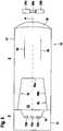
Diese Ausbildung des Konzentrators erweist sich insbesondere dann als vorteilhaft, wenn der Sender einen Reflektortrichter aufweist, auf dessen Boden wenigstens ein Sendelichtstrahlen emittierendes Sendeelement angeordnet ist.This design of the concentrator proves to be particularly advantageous when the transmitter has a reflector funnel, on the bottom of which at least one transmitter element that emits transmitted light rays is arranged.

Bei dieser Anordnung gelangt zwar der Großteil der vom Sendeelement emittierten Sendelichtstrahlen direkt zum Konzentrator und wird in diesen entlang der Längsachse des Konzentrators geführt, so dass die so geführten Sendelichtstrahlen nach Austritt aus dem Konzentrator ein Sendelichtbündel bilden, das zur Objektdetektion verwendet wird. Jedoch treten auch parasitäre Sendelichtstrahlen auf, die vom Sendeelement emittiert und dann erst nach Reflexion an der Wand des Reflektortrichters in den Konzentrator eingekoppelt werden. Diese parasitären Sendelichtstrahlen, deren Strahlachsen in einem Winkel zur Längsachse des Konzentrators verlaufen, der größer ist als der Selektionswinkel, werden durch die Geometrie der Einkoppelfläche vollständig ausgeblendet, so dass die Sendelichtstrahlen, die aus dem Konzentrator geführt sind, einen scharf begrenzten Sendelichtfleck aufweisen.With this arrangement, the majority of the transmitted light rays emitted by the transmitter element reach the concentrator directly and are guided along the longitudinal axis of the concentrator, so that the transmitted light rays, after exiting the concentrator, form a transmitted light bundle that is used for object detection. However, parasitic transmitted light rays also occur, which are emitted by the transmitting element and then only after being reflected on the wall of the reflector funnel into the Concentrator are coupled. These parasitic transmitted light beams, the beam axes of which run at an angle to the longitudinal axis of the concentrator that is greater than the selection angle, are completely masked out by the geometry of the coupling surface, so that the transmitted light beams that are guided out of the concentrator have a sharply delimited transmitted light spot.

Im einfachsten Fall weist der Sender nur ein einzelnes Sendeelement im Reflektortrichter auf.In the simplest case, the transmitter has only a single transmitter element in the reflector funnel.

Alternativ weist der Sender mehrere nebeneinander angeordnete Sendeelemente auf, wobei die Sendeelemente Sendelichtstrahlen in unterschiedlichen Farben emittieren.Alternatively, the transmitter has a plurality of transmitter elements arranged next to one another, the transmitter elements emitting transmitted light beams in different colors.

Der so ausgebildete optische Sensor bildet dann vorteilhaft einen Kontrasttaster, mit welchem eine Kontrastunterscheidung an Objekten durchgeführt werden kann.The optical sensor designed in this way then advantageously forms a contrast scanner with which a contrast differentiation can be carried out on objects.

Die Erfindung wird im Folgenden anhand der Zeichnungen erläutert. Es zeigen:

  • 1: Schematische Darstellung eines optischen Sensors.
  • 2: Darstellung einer Ausführungsform des Senders und der Sendeoptik des optischen Sensors gemäß1 nachDE 10 2008 014 349.
  • 3: Querschnittdarstellung einer Halterung für dieSendeoptik gemäß2.
  • 4: Darstellung eines ersten Ausführungsbeispiels der erfindungsgemäßen Sendeoptik mit zugeordnetem Sender für einen optischenSensor gemäß1.
  • 5: Darstellung eines zweiten Ausführungsbeispiels der erfindungsgemäßen Sendeoptik mit zugeordnetem Sender für einen optischenSensor gemäß2.
The invention is explained below with reference to the drawings. Show it:
  • 1 : Schematic representation of an optical sensor.
  • 2 : Representation of an embodiment of the transmitter and the transmission optics of the optical sensor according to FIG 1 afterDE 10 2008 014 349 .
  • 3 : Cross-sectional representation of a holder for the transmission optics according to 2 .
  • 4th : Representation of a first embodiment of the transmission optics according to the invention with an assigned transmitter for an optical sensor according to FIG 1 .
  • 5 : Representation of a second exemplary embodiment of the transmission optics according to the invention with an assigned transmitter for an optical sensor according to FIG 2 .

1 zeigt schematisch den Aufbau eines optischen Sensors1 zur Erfassung von Objekten2 in einem Überwachungsbereich. Der optische Sensor1 ist im vorliegenden Fall als Lichttaster, insbesondere Kontrasttaster ausgebildet. Prinzipiell kann der optische Sensor auch als Distanzsensor, Lichtschranke, Reflexionslichtschranke oder dergleichen gebildet sein.1 shows schematically the structure of anoptical sensor 1 for capturingobjects 2 in a surveillance area. Theoptical sensor 1 is designed in the present case as a light scanner, in particular a contrast scanner. In principle, the optical sensor can also be designed as a distance sensor, light barrier, reflection light barrier or the like.

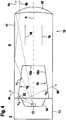
Der optische Sensor gemäß1 weist ein Sensorgehäuse3 auf, in welchem ein Sendelichtstrahlen4 emittierender Sender5 mit einer zugeordneten Sendeoptik6 und ein Empfangslichtstrahlen7 empfangender Empfänger8 mit einer zugeordneten Empfangsoptik9 angeordnet sind. Der Sender5 ist im vorliegenden Fall von einer Leuchtdiode gebildet. Prinzipiell kann der Sender5 auch von einer Laserdiode gebildet sein. Der Empfänger8 kann von einem einzelnen Empfangselement wie einer Photodiode gebildet sein. Alternativ kann der Empfanger8 mehrere Empfangselemente aufweisen. Die Sendeoptik6 dient zur Strahlformung der Sendelichtstrahlen4. Die Empfangsoptik9 dient zur Fokussierung der Empfangslichtstrahlen7 auf den Empfänger8.The optical sensor according to 1 has asensor housing 3 on, in which a transmitted light rays4th emitting transmitter 5 with an assigned transmission optics 6th and a receiving light beam 7th receiving recipient 8th with an assigned receivingoptics 9 are arranged. Thetransmitter 5 is formed in the present case by a light emitting diode. In principle, the sender can 5 also be formed by a laser diode. The recipient 8th can be formed by a single receiving element such as a photodiode. Alternatively, the recipient can 8th have multiple receiving elements. The transmission optics 6th serves for beam shaping of the transmitted light rays 4th . The receivingoptics 9 serves to focus the received light beams 7th on the recipient 8th .

Die vom Sender5 emittierten Sendelichtstrahlen4 werden in den Überwachungsbereich geführt und treffen auf ein zu detektierendes Objekt2. Von dort werden die Sendelichtstrahlen4 als Empfangslichtstrahlen7 zurück zum Empfänger8 reflektiert. Die dabei generierten Empfangssignale werden in einer Auswerteeinheit10 ausgewertet, die ebenfalls im Sensorgehäuse3 integriert ist. Die Auswerteeinheit10 ist von einem Mikroprozessor oder dergleichen gebildet. In der Auswerteeinheit10 wird beispielsweise durch eine Schwellwertbewertung ein Objektfeststellungssignal generiert. Das Objektfeststellungssignal wird über einen nicht dargestellten Ausgang des optischen Sensors1 ausgegeben.The one from thebroadcaster 5 emitted transmitted light rays 4th are led into the surveillance area and hit an object to be detected 2 . From there the transmitted light rays 4th as received light rays 7th back to the recipient 8th reflected. The received signals generated in the process are processed in anevaluation unit 10 evaluated, which is also in thesensor housing 3 is integrated. Theevaluation unit 10 is formed by a microprocessor or the like. In theevaluation unit 10 For example, an object detection signal is generated by a threshold value evaluation. The object detection signal is transmitted via an output, not shown, of theoptical sensor 1 issued.

2 zeigt eine Ausführung des Senders5 und der zugeordneten Sendeoptik6 für den optischen Sensor1 gemäß1 nachDE 10 20008 014 349. Der von einer Leuchtdiode gebildete Sender5 ist in einem Gehäuse11 integriert, in dessen Frontwand ein Fenster12 vorgesehen ist, welches auch in Form einer transparenten Vergussmasse ausgebildet sein kann. Die Sendelichtstrahlen4 werden von einem Sendeelement13 in Form eines Chips13 emittiert, der von einem Reflektortrichter14 umgeben ist. Das vom Sendeelement13 emittierte Sendelicht gelangt direkt oder nach Reflexion an dem Reflektortrichter14 aus dem Sender5. Die so generierten Sendelichtstrahlen4 des Senders5 weisen generell eine divergierte Strahlcharakteristik auf.2 shows an implementation of thetransmitter 5 and the assigned transmission optics 6th for theoptical sensor 1 according to 1 after DE 102 008 014 349 . The transmitter formed by a light-emittingdiode 5 is in ahousing 11 integrated, in its front wall a window 12th is provided, which can also be designed in the form of a transparent potting compound. The transmitted light rays 4th are from a sending element 13th in the form of a chip 13th emitted by a reflector funnel 14th is surrounded. That from the sending element 13th emitted transmitted light arrives directly or after reflection at the reflector funnel 14th from thetransmitter 5 . The transmitted light rays generated in this way 4th of thetransmitter 5 generally have a divergent beam characteristic.

Die Sendeoptik6 weist einen Konzentrator15 auf, der in Form eines transparenten Kunststoff-Spritzgussteils ausgebildet ist. Wie aus2 ersichtlich, ist der Konzentrator15 unmittelbar auf den Sender5 so aufgesetzt, dass die LängsachseA des Konzentrators15 mit der optischen Achse des Senders5 zusammenfällt.The transmission optics 6th has a concentrator 15th on, which is designed in the form of a transparent plastic injection-molded part. How out 2 visible is the concentrator 15th directly to thetransmitter 5 placed so that the longitudinal axis A. of the concentrator 15th with the optical axis of thetransmitter 5 coincides.

An der dem Sender5 zugewandten Stirnseite des Konzentrators15 ist eine Einkoppelfläche16 vorgesehen, über welche die vom Sender5 emittierten Sendelichtstrahlen4 in den Konzentrator15 eingekoppelt werden. Im vorliegenden Fall ist die Einkoppelfläche16 konkav ausgebildet und bildet dadurch ein optisches Element, mit welchem die Sendelichtstrahlen4 in den Konzentrator15 geführt werden. Die Einkoppelfläche16 ist dabei als sphärische Fläche ausgebildet. Alternativ kann die Einkoppelfläche16 auch als asphärische Fläche oder als Freiformfläche ausgebildet sein. Wesentlich ist generell, dass der Konzentrator15 mit der Einkoppelfläche16 direkt an den Sender5 anschließt und dabei bevorzugt die gesamte Fläche des Fensters12 abdeckt, so dass die gesamten oder wenigstens nahezu die gesamten Sendelichtstrahlen4 über die Einkoppelfläche16 in den Konzentrator15 eingekoppelt werden.At thetransmitter 5 facing end face of the concentrator 15th is acoupling surface 16 provided over which thetransmitter 5 emitted transmitted light rays 4th into the concentrator 15th are coupled. In the present case is thecoupling area 16 concave and thereby forms an optical element with which the transmitted light rays 4th into the concentrator 15th be guided. Thecoupling area 16 is designed as a spherical surface. Alternatively, thecoupling surface 16 can also be designed as an aspherical surface or as a free-form surface. It is generally essential that the concentrator 15th with thecoupling surface 16 directly to thetransmitter 5 follows and prefers the entire area of the window 12th covers so that all or at least almost all of the transmitted light rays 4th over thecoupling surface 16 into the concentrator 15th are coupled.

Die Sendelichtstrahlen4 werden dann innerhalb des Konzentrators15 in Richtung dessen LängsachseA geführt. Die Mantelfläche17 des Konzentrators15 ist so geformt, dass an dieser eine Totalreflexion der Sendelichtstrahlen4 erfolgt, wodurch gewährleistet ist, dass nahezu kein Sendelicht über die Mantelfläche17 austritt. Besonders vorteilhaft ist die Mantelfläche17 verspiegelt, so dass über diese keine Sendelichtstrahlen4 mehr austreten.The transmitted light rays 4th are then inside the concentrator 15th in the direction of its longitudinal axis A. guided. The outer surface 17th of the concentrator 15th is shaped in such a way that there is a total reflection of the transmitted light rays 4th takes place, which ensures that almost no transmitted light over the lateral surface 17th exit. The jacket surface is particularly advantageous 17th mirrored, so that there are no rays of light transmitted through them 4th leak more.

Die Mantelfläche17 des Konzentrators15 ist so ausgebildet, dass eine vollständige Führung der Sendelichtstrahlen4 im Konzentrator15 erhalten wird. Zudem trägt die Gestaltung der Mantelfläche17 auch zur Strahlformung der Sendelichtstrahlen4 bei. Im vorliegenden Fall weist die Mantelfläche17 eine parabolische Form auf. Prinzipiell kann die Mantelfläche17 eine zumindest segementweise zylindrische Form aufweisen. Weiterhin kann die Mantelfläche17 als Freiformfläche ausgebildet sein.The outer surface 17th of the concentrator 15th is designed so that a complete guidance of the transmitted light rays 4th in the concentrator 15th is obtained. In addition, the design of the outer surface contributes 17th also for beam shaping of the transmitted light rays 4th at. In the present case, the lateral surface 17th a parabolic shape. In principle, the outer surface 17th have an at least segmentally cylindrical shape. Furthermore, the jacket surface 17th be designed as a freeform surface.

An der dem Sender5 abgewandten Stirnseite des Konzentrators15 ist eine Austrittsfläche18 vorgesehen, über welche die Sendelichtstrahlen4 aus dem Konzentrator15 geführt werden. Durch eine spezifische Formgebung der Austrittsfläche18 kann das Strahlprofil der Sendelichtstrahlen4 genau vorgegeben werden. Im vorliegenden Ausführungsbeispiel weist die Austrittsfläche18 die Form einer torischen Fläche auf. Mit einer derart ausgebildeten Austrittsfläche18 können, ohne Einsatz zusätzlicher Optikelemente wie Blenden und dergleichen, Sendelichtstrahlen4 mit einem quadratischen oder rechteckigen Strahlquerschnitt erzeugt werden. Generell kann die Austrittsfläche18 auch von anderen konvexen Flächen wie sphärischen Flächen, asphärischen Flächen oder Freiformflächen gebildet sein.At thetransmitter 5 facing away from the front of the concentrator 15th is an exit surface 18th provided over which the transmitted light beams 4th from the concentrator 15th be guided. Through a specific shape of the exit surface 18th can be the beam profile of the transmitted light rays 4th are precisely specified. In the present exemplary embodiment, the exit surface 18th the shape of a toric surface. With an exit surface designed in this way 18th can transmit light beams without the use of additional optical elements such as diaphragms and the like 4th can be generated with a square or rectangular beam cross-section. In general, the exit area 18th can also be formed by other convex surfaces such as spherical surfaces, aspherical surfaces or freeform surfaces.

In2 sind zwei von insgesamt drei Linien auf den Mantelflächen17 dargestellt, die Auflagelinien19 zur Auflage von Elementen einer Halterung20 bilden, die in3 in einer Querschnittsdarstellung dargestellt ist.In 2 are two of a total of three lines on the lateral surfaces 17th shown, the support lines 19th for supporting elements of a bracket 20th form that in 3 is shown in a cross-sectional view.

Mit der Halterung20 wird der die Sendeoptik6 bildende Konzentrator15 in dem Sensorgehäuse3 des optischen Sensors1 ortsfest gelagert, so dass er in der vorgesehenen Sollposition zu dem ebenfalls im Sensorgehäuse3 ortsfest gelagerten Sender5 positioniert ist.With the bracket 20th will be the transmission optics 6th educational concentrator 15th in thesensor housing 3 of theoptical sensor 1 stored in a stationary manner, so that it is in the intended target position in relation to the one in thesensor housing 3Stationary transmitter 5 is positioned.

Die Halterung20 gemäß3 bildet eine Dreipunktlagerung für den Konzentrator15. Die Halterung20 weist eine ringförmige Aufnahme21 auf, von deren Innenseite drei identisch ausgebildete Kontaktelemente22 hervorstehen. Die Kontaktelemente22 sind in Umfangsrichtung der Aufnahme21 jeweils um 120° versetzt zueinander angeordnet. Die Kontaktelemente22 sind linienformig ausgebildet, wobei deren parallel zueinander verlaufende LängsachsenA senkrecht zur Zeichenebene in3 orientiert sind. Die Kontaktelemente22 weisen jeweils zwei Seitenflächen auf, die auf eine Vorderkante zulaufen. Mit diesen Vorderkanten liegen die Kontaktelemente22 der Halterung20 entlang der Auflagelinien19 an der Mantelfläche17 des Konzentrators15 an. Da somit die Kontaktelemente22 nur linienförmige, keine großflächigen Auflageflächen auf der Mantelfläche17 des Konzentrators15 bilden, ist gewährleistet, dass dort nur ein sehr geringer Anteil der Sendelichtstrahlen4 austritt.The bracket 20th according to 3 forms a three-point bearing for the concentrator 15th . The bracket 20th has anannular receptacle 21 on, from the inside of which there are three identical contact elements 22nd protrude. The contact elements 22nd are in the circumferential direction of therecording 21 each arranged offset from one another by 120 °. The contact elements 22nd are linear, with their longitudinal axes running parallel to one another A. perpendicular to the plane of the drawing in 3 are oriented. The contact elements 22nd each have two side surfaces that taper towards a front edge. The contact elements lie with these front edges 22nd the bracket 20th along the support lines 19th on the outer surface 17th of the concentrator 15th at. As the contact elements 22nd only linear, no large contact surfaces on the outer surface 17th of the concentrator 15th form, it is ensured that there only a very small proportion of the transmitted light rays 4th exit.

Die4 und5 zeigen zwei Ausführungsformen des erfindungsgemäßen Konzentrators15 als Bestandteil der Sendeoptik6 des optischen Sensors1 mit dem jeweils zugeordneten Sender5.the 4th and 5 show two embodiments of the concentrator according to the invention 15th as part of the transmission optics 6th of theoptical sensor 1 with the respective assignedtransmitter 5 .

Die Konzentratoren15 der4 und5 weisen analog zur Ausführungsform gemäß2 eine Mantelfläche17 und eine konvexe Austrittsfläche18 auf. Der Konzentrator15 selbst ist rotationssymmetrisch bezüglich seiner LängsachseA ausgebildet und besteht bevorzugt aus einem Kunststoff-Spritzgussteil. An der Mantelfläche17 erfolgt eine Totalreflexion der Sendelichtstrahlen4, wobei hierzu die Mantelfläche17 verspiegelt oder aufgeraut sein kann. Durch die spezifische Ausbildung der Austrittsfläche18 kann ein spezifischer Strahlquerschnitt der Sendelichtstrahlen4, das heißt eine spezifische Form des Sendelichtflecks, erhalten werden. Insbesondere kann ein quadratischer Sendelichtfleck erzeugt werden. Die Außenkontur des Konzentrators15 gemäß4 beziehungsweise5 entspricht bevorzugt der Ausführungsform gemäß2.The concentrators 15th the 4th and 5 have analogous to the embodiment according to 2 a lateral surface 17th and a convex exit surface 18th on. The concentrator 15th itself is rotationally symmetrical with respect to its longitudinal axis A. formed and preferably consists of a plastic injection molded part. On the outer surface 17th there is a total reflection of the transmitted light rays 4th , for this purpose the lateral surface 17th can be mirrored or roughened. Due to the specific design of the exit surface 18th can be a specific beam cross-section of the transmitted light beams 4th , that is, a specific shape of the transmission light spot can be obtained. In particular, a square emitted light spot can be generated. The outer contour of the concentrator 15th according to 4th respectively 5 preferably corresponds to the embodiment according to 2 .

Analog zur Ausführungsform gemäß2 sind bei dem Konzentrator15 gemäß den4 und5 Auflagelinien19 vorgesehen, auf welchen die Halterung gemäß3 aufgelegt werden kann.Analogous to the embodiment according to 2 are at the concentrator 15th according to the 4th and 5 Support lines 19th provided on which the bracket according to 3 can be placed.

Im Unterschied zur Ausführungsform gemäß2 begrenzt bei dem Konzentrator15 gemäß4 beziehungsweise5 die Einkoppelfläche16 einen trichterförmigen Hohlraum23, der an der dem Sender5 zugewandten Stirnseite des Konzentrators15 ausmündet.In contrast to the embodiment according to 2 limited at the concentrator 15th according to 4th respectively 5 thecoupling area 16 a funnel-shapedcavity 23 who at the thetransmitter 5 facing end face of the concentrator 15th empties.

Die Einkoppelfläche16 ist dabei unterteilt in eine Stirnfläche16a, die den Boden des Hohlraums23 begrenzt und deren Normalenvektor mit der LängsachseA des Konzentrators15 zusammenfällt, sowie in ein Mantelflächensegment16b, das den Hohlraum23 seitlich begrenzt.Thecoupling area 16 is divided into anend face 16a that is the bottom of thecavity 23 and their normal vector with the longitudinal axis A. of the concentrator 15th coincides, as well as in aperipheral surface segment 16b that is thecavity 23 laterally limited.

Der Hohlraum23 weist im vorliegenden Fall eine konische, sich der Stirnfläche16a hin verjüngende Form auf, wobei der Querschnitt des Hohlraums23 trapezförmig ist. Prinzipiell kann das Mantelflächensegment16b des Hohlraums23 auch eine Krümmung aufweisen.Thecavity 23 has in the present case a conical, facing theend face 16a tapering shape, the cross-section of thecavity 23 is trapezoidal. In principle, thejacket surface segment 16b of thecavity 23 also have a curvature.

Durch diese Ausbildung der Einkoppelfläche16 können vom Sender5 emittierte, achsferne, das heißt in großen Winkeln zur LängsachseA des Konzentrators15 verlaufende Sendelichtstrahlen4, gezielt ausgeblendet werden, so dass nur achsnahe Sendelichtstrahlen4 zur Bildung eines scharf begrenzten Sendelichtflecks beitragen.Through this formation of thecoupling surface 16 can from thebroadcaster 5 emitted off-axis, i.e. at large angles to the longitudinal axis A. of the concentrator 15th running transmitted light rays 4th , are specifically masked out so that only near-axis transmitted light beams 4th contribute to the formation of a sharply delimited light spot.

Dies ist anhand des Ausführungsbeispiels gemäß4 veranschaulicht. Bei dieser Ausführungsform ist ein Sender5 vorgesehen, der in einem Gehäuse11 integriert ist. In dem Gehäuse11 befindet sich ein Reflektortrichter14, auf dessen Boden ein Sendeelement13 in Form einer Leuchtdiode oder einer Laserdiode aufsitzt.This is based on the exemplary embodiment according to 4th illustrated. In this embodiment there is atransmitter 5 provided in ahousing 11 is integrated. In thecase 11 there is a reflector funnel 14th on the bottom of which a transmitter element 13th in the form of a light emitting diode or a laser diode.

Die vom Sender5 emittierten Sendelichtstrahlen4 gelangen über die offene Oberseite des Reflektortrichters14 zum Konzentrator15. In4 sind zwei achsnahe Teilstrahlen4a,4b dargestellt. Der Teilstrahl4a trifft direkt auf die Stirnfläche16a und gelangt so in den Konzentrator15. Der Teilstrahl4b trifft in einem Winkel α1 auf das Mantelflächensegment16b, der kleiner als ein durch die Geometrie des Mantelflächensegments16b bestimmter Selektionswinkel ist, so dass der Teilstrahl4b über das Mantelflächensegment16b auf die Mantelfläche17 des Konzentrators15 so geführt wird, dass der Teilstrahl4b dort total reflektiert wird und dann ebenso wie der Teilstrahl4a über die Austrittsfläche18 aus dem Konzentrator15 austritt. Damit tragen diese Teilstrahlen4a,4b zur Bildung des Sendelichtflecks der Sendelichtstrahlen4, die zur Objektdetektion im Überwachungsbereichs dienen, bei.The one from thebroadcaster 5 emitted transmitted light rays 4th get over the open top of the reflector funnel 14th to the concentrator 15th . In 4th are two partial beams close to theaxis 4a , 4b shown. Thepartial beam 4a hits the face directly 16a and so gets into the concentrator 15th . Thepartial beam 4b meets the lateral surface segment at anangle α1 16b that is smaller than one due to the geometry of theperipheral surface segment 16b certain selection angle is so that thepartial beam 4b over thesurface segment 16b on the outer surface 17th of the concentrator 15th is guided so that thepartial beam 4b there is totally reflected and then just like thepartial beam 4a over the exit surface 18th from the concentrator 15th exit. This means that these partial beams carry 4a , 4b to form the emitted light spot of the emitted light rays 4th , which are used for object detection in the surveillance area.

Weiterhin sind in4 zwei achsfreie Teilstrahlen4c,4d dargestellt. Der Teilstrahl4c gelangt vom Sendeelement13 ohne Reflexion am Reflektortrichter14 in den Hohlraum23 und trifft in einen Winkel α2 auf das Mantelflächensegment16b, der größer als der Selektionswinkel ist. Damit trifft der Teilstrahl4c in einem Winkel auf die Mantelfläche17 der Konzentratoren15, der größer ist als der Grenzwinkel der Totalreflexion. Damit wird dieser Teilstrahl4c über die Mantelfläche17 aus dem Konzentrator15 ausgeleitet und trägt nicht zur Bildung des Sendelichtflecks der Sendelichtstrahlen4, der zur Objektdetektion genutzt wird, bei. Der vom Sendeelement13 emittierte Teilstrahl4d wird zunächst an der Seitenwand des Reflektortrichters14 reflektiert und trifft dann in einem Winkel α3 auf das Mantelflächensegment16b, der ebenfalls größer als der Selektionswinkel ist. Damit trifft auch der Teilstrahl4d in einem Winkel auf die Mantelfläche17 des Konzentrators15, der größer ist als der Winkel der Totalreflexion. Somit wird auch der Teilstrahl4d über die Mantelfläche17 aus dem Konzentrator15 geführt und somit ausgeblendet.Furthermore, in 4th two axis-freepartial beams 4c , 4d shown. Thepartial beam 4c comes from the transmitter element 13th without reflection on the reflector funnel 14th into thecavity 23 and meets the lateral surface segment at anangle α2 16b that is larger than the selection angle. The partial beam thus hits 4c at an angle on the lateral surface 17th the concentrators 15th , which is greater than the critical angle of total reflection. This becomes thispartial beam 4c over the outer surface 17th from the concentrator 15th diverted and does not contribute to the formation of the transmission light spot of the transmission light rays 4th , which is used for object detection. The one from the sending element 13th emittedpartial beam 4d is first on the side wall of the reflector funnel 14th reflects and then hits thesurface segmentat an angle α 3 16b , which is also larger than the selection angle. This means that the partial beam also hits 4d at an angle on the lateral surface 17th of the concentrator 15th which is greater than the angle of total internal reflection. Thus the partial beam is also 4d over the outer surface 17th from the concentrator 15th guided and thus hidden.

Generell werden durch Vorgabe der Hohlraumgeometrie und damit der Geometrie der Einkoppelfläche16 achsferne Sendelichtstrahlen-Anteile ausgeblendet, so dass nur achsnahe Sendelichtstrahlen-Anteile über die Austrittsfläche18 des Konzentrators15 in den Überwachungsbereich gelangen. Dadurch wird ein scharf begrenzter, symmetrisch zur Längsachse liegender Sendelichtfleck der Sendelichtstrahlen4 generiert.In general, by specifying the cavity geometry and thus the geometry of thecoupling surface 16 off-axis components of the transmitted light rays are masked out, so that only those components of the transmitted light rays close to the axis pass over the exit surface 18th of the concentrator 15th get into the monitoring area. This creates a sharply delimited, symmetrical to the longitudinal axis of the transmitted light spot of the transmitted light rays 4th generated.

Die Ausführungsform gemäß5 unterscheidet sich von der Ausführungsform gemäß4 dadurch, dass der Sender5 mehrere nebeneinander liegende, auf dem Boden des Reflektortrichters15 angeordnete Sendeelemente13a,13b,13c aufweist, die zusammen oder einzeln nacheinander aktiviert werden können und welche Sendelichtstrahlen4 in unterschiedlichen Farben emittieren.The embodiment according to 5 differs from the embodiment according to 4th by having thesender 5 several lying next to each other on the floor of the reflector funnel 15th arranged transmittingelements 13a , 13b , 13c which can be activated together or individually one after the other and which transmission light beams 4th emit in different colors.

Im vorliegenden Fall sind drei Sendeelemente13a,b,c vorgesehen. Das zentrale Sendeelement13a emittiert grüne Sendelichtstrahlen4, wodurch ein symmetrisch zur Längsachse liegender Lichtfleck24a generiert wird. Die daneben liegenden Sendeelemente13b,13c emittieren rote beziehungsweise blaue Sendelichtstrahlen4, wodurch achsversetzt neben dem grünen Lichtfleck24a ein roter Lichtfleck24b und ein blauer Lichtfleck24c generiert wird. Die Ausblendung achsferner Teil-Sendelichtstrahlen erfolgt analog zur Ausführungsform gemäß4 durch eine geeignete Wahl der Geometrie der Einkoppelfläche16, insbesondere des Mantelflächensegments16b.In the present case there are threetransmission elements 13a , b , c intended. Thecentral transmission element 13a emits green light rays 4th , creating a light spot that is symmetrical to thelongitudinal axis 24a is generated. Theadjacent transmission elements 13b , 13c emit red or blue light rays 4th , whereby off-axis next to thegreen light spot 24a a red spot of light 24b and a blue spot of light 24c is generated. The partial transmission light rays remote from the axis are masked out analogously to the embodiment according to FIG 4th by a suitable choice of the geometry of thecoupling surface 16 , in particular of thesurface segment 16b .

BezugszeichenlisteList of reference symbols

(1)(1)
Optischer SensorOptical sensor
(2)(2)
Objektobject
(3)(3)
SensorgehäuseSensor housing
(4)(4)
SendelichtstrahlenTransmitted light rays
(4a)(4a)
TeilstrahlPartial beam
(4b)(4b)
TeilstrahlPartial beam
(4c)(4c)
TeilstrahlPartial beam
(4d)(4d)
TeilstrahlPartial beam
(5)(5)
SenderChannel
(6)(6)
SendeoptikTransmission optics
(7)(7)
EmpfangslichtstrahlenReceiving light beams
(8)(8th)
Empfängerrecipient
(9)(9)
EmpfangsoptikReceiving optics
(10)(10)
AuswerteeinheitEvaluation unit
(11)(11)
Gehäusecasing
(12)(12)
Fensterwindow
(13)(13)
SendeelementSending element
(13a)(13a)
SendeelementSending element
(13b)(13b)
SendeelementSending element
(13c)(13c)
SendeelementSending element
(14)(14)
ReflektortrichterReflector funnel
(15)(15)
KonzentratorConcentrator
(16)(16)
EinkoppelflächeCoupling surface
(16a)(16a)
StirnflächeFace
(16b)(16b)
MantelflächensegmentLateral surface segment
(17)(17)
MantelflächeOuter surface
(18)(18)
AustrittsflächeExit surface
(19)(19)
AuflagelinieSupport line
(20)(20)
Halterungbracket
(21)(21)
Aufnahmerecording
(22)(22)
KontaktelementContact element
(23)(23)
Hohlraumcavity
(24a)(24a)
LichtfleckLight spot
(24b)(24b)
LichtfleckLight spot
(24c)(24c)
LichtfleckLight spot
(A)(A)
LängsachseLongitudinal axis

Claims (17)

Translated fromGerman
Optischer Sensor (1) zur Erfassung von Objekten (2) in einem Überwachungsbereich, mit einem Sendelichtstrahlen (4) emittierenden Sender (5), einem Empfangslichtstrahlen (7) empfangenden Empfänger (8), einer Auswerteeinheit (10), in welcher in Abhängigkeit der Empfangssignale am Ausgang des Empfängers (8) ein Objektfeststellungssignal generiert wird, und mit einer dem Sender (5) nachgeordneten Sendeoptik (6) zur Strahlformung der Sendelichtstrahlen (4), wobei die Sendeoptik (6) unmittelbar an den Sender (5) anschließt und einen Konzentrator (15) aufweist, der ein Lichtführungselement für die Sendelichtstrahlen (4) bildet, wobei hierzu an der Mantelfläche (17) des Konzentrators (15) eine Totalreflexion der Sendelichtstrahlen (4) erfolgt, wobei die dem Sender (5) zugeordnete Stirnseite des Konzentrators (15) als Einkoppelfläche (16) für die Sendelichtstrahlen (4) ausgebildet ist, und wobei an der dem Sender (5) abgewandten Stirnseite des Konzentrators (15) eine Austrittsfläche (18) vorgesehen ist, welche ein Strahlformungsmittel für die Sendelichtstrahlen (4) bildet, gemäß DE 10 2008 014 349 B4,dadurch gekennzeichnet, dass die Einkoppelfläche (16) einen trichterförmigen Hohlraum (23) begrenzt, der an der Stirnseite des Konzentrators (15) ausmündet, dass die Einkoppelfläche eine Stirnfläche (16a), deren Normalenvektor mit der Längsachse des Konzentrators (15) zusammen fällt, und ein zur Längsachse des Konzentrators (15) rotationssymmetrisches Mantelflächensegment (16b) aufweist, dass aus dem Sender (5) austretende Sendelichtstrahlen (4), deren Strahlachsen in einem Winkel zur Längsachse des Konzentrators (15) verlaufen, der größer als ein Selektionswinkel ist, über das Mantelflächensegment (16b) aus dem Konzentrator (15) ausgekoppelt und dadurch ausgeblendet werden, und dass das Mantelflächensegment (16b) eine konische Form aufweist.Optical sensor (1) for detecting objects (2) in a monitoring area, with a transmitter (5) emitting transmitted light beams (4), a receiver (8) receiving received light beams (7), an evaluation unit (10) in which, depending on the Received signals at the output of the receiver (8) an object detection signal is generated, and with a transmission optics (6) downstream of the transmitter (5) for beam shaping of the transmitted light beams (4), the transmission optics (6) directly connected to the transmitter (5) and a Has concentrator (15) which forms a light guide element for the transmitted light rays (4), for this purpose a total reflection of the transmitted light rays (4) takes place on the lateral surface (17) of the concentrator (15), the end face of the concentrator assigned to the transmitter (5) (15) is designed as a coupling surface (16) for the transmitted light beams (4), and an exit surface (18) is provided on the end face of the concentrator (15) facing away from the transmitter (5) ehen, which forms a beam shaping means for the transmitted light rays (4), according to DE 10 2008 014 349 B4,characterized in that the coupling surface (16) delimits a funnel-shaped cavity (23) which opens out on the end face of the concentrator (15), that the coupling surface has an end face (16a), the normal vector of which coincides with the longitudinal axis of the concentrator (15), and a circumferential surface segment (16b) that is rotationally symmetrical to the longitudinal axis of the concentrator (15), that transmitted light rays (4) emerging from the transmitter (5) , the beam axes of which extend at an angle to the longitudinal axis of the concentrator (15) which is greater than a selection angle, are decoupled from the concentrator (15) via the surface segment (16b) and thereby masked out, and that the surface segment (16b) has a conical shape having.Optischer Sensor nachAnspruch 1,dadurch gekennzeichnet, dass der Konzentrator (15) rotationssymmetrisch bezüglich seiner Längsachse ausgebildet ist.Optical sensor after Claim 1 ,characterized in that the concentrator (15) is designed to be rotationally symmetrical with respect to its longitudinal axis.Optischer Sensor nach einem derAnsprüche 1 oder2,dadurch gekennzeichnet, dass sich der Durchmesser des Hohlraums (23) von der dem Sender (5) zugewandten Stirnseite des Konzentrators (15) zur Stirnfläche der Einkoppelfläche (16) hin verjüngt.Optical sensor according to one of the Claims 1 or 2 ,characterized in that the diameter of the cavity (23) tapers from the end face of the concentrator (15) facing the transmitter (5) to the end face of the coupling surface (16).Optischer Sensor nach einem derAnsprüche 1 bis3,dadurch gekennzeichnet, dass der Sender (5) einen Reflektortrichter (14) aufweist, auf dessen Boden wenigstens ein Sendelichtstrahlen (4) emittierendes Sendeelement (13, 13a, b, c) angeordnet ist.Optical sensor according to one of the Claims 1 until 3 ,characterized in that the transmitter (5) has a reflector funnel (14), on the bottom of which at least one transmitter element (13, 13a, b, c) emitting light rays (4) is arranged.Optischer Sensor nachAnspruch 4,dadurch gekennzeichnet, dass der Sender (5) mehrere nebeneinander angeordnete Sendeelemente (13a, b, c) aufweist.Optical sensor after Claim 4 ,characterized in that the transmitter (5) has a plurality of transmitter elements (13a, b, c) arranged next to one another.Optischer Sensor nachAnspruch 5,dadurch gekennzeichnet, dass die Sendeelemente (13a, b, c) Sendelichtstrahlen (4) in unterschiedlichen Farben emittieren.Optical sensor after Claim 5 ,characterized in that the transmitting elements (13a, b, c) emit transmitting light beams (4) in different colors.Optischer Sensor nach einem derAnsprüche 1 bis6,dadurch gekennzeichnet, dass die Sendelichtstrahlen (4) im Konzentrator (15) entlang dessen Längsachse geführt sind.Optical sensor according to one of the Claims 1 until 6th ,characterized in that the transmitted light beams (4) are guided in the concentrator (15) along its longitudinal axis.Optischer Sensor nach einem derAnsprüche 1 bis7,dadurch gekennzeichnet, dass der Konzentrator (15) eine parabolische Mantelfläche (17) aufweist.Optical sensor according to one of the Claims 1 until 7th ,characterized in that the concentrator (15) has a parabolic jacket surface (17).Optischer Sensor nach einem derAnsprüche 1 bis7,dadurch gekennzeichnet, dass die Mantelfläche (17) des Konzentrators (15) eine zylindrische Form aufweist oder eine Freiformfläche bildet.Optical sensor according to one of the Claims 1 until 7th ,characterized in that the jacket surface (17) of the concentrator (15) has a cylindrical shape or forms a free-form surface.Optischer Sensor nach einem derAnsprüche 1 bis9,dadurch gekennzeichnet, dass die Austrittsfläche (18) eine konvexe Fläche ist.Optical sensor according to one of the Claims 1 until 9 ,characterized in that the exit surface (18) is a convex surface.Optischer Sensor nachAnspruch 10,dadurch gekennzeichnet, dass die Austrittsfläche (18) des Konzentrators (15) als torische Fläche ausgebildet ist.Optical sensor after Claim 10 ,characterized in that the exit surface (18) of the concentrator (15) is designed as a toric surface.Optischer Sensor nachAnspruch 10,dadurch gekennzeichnet, dass die Austrittsfläche (18) des Konzentrators (15) als sphärische oder asphärische Fläche oder als Freiformfläche ausgebildet ist.Optical sensor after Claim 10 ,characterized in that the exit surface (18) of the concentrator (15) is designed as a spherical or aspherical surface or as a free-form surface.Optischer Sensor nach einem derAnsprüche 1 bis12,dadurch gekennzeichnet, dass der Konzentrator (15) aus Kunststoff besteht.Optical sensor according to one of the Claims 1 until 12th ,characterized in that the concentrator (15) consists of plastic.Optischer Sensor nach einem derAnsprüche 1 bis13,dadurch gekennzeichnet, dass die Mantelfläche (17) des Konzentrators (15) verspiegelt oder aufgeraut ist.Optical sensor according to one of the Claims 1 until 13th ,characterized in that the lateral surface (17) of the concentrator (15) is mirrored or roughened.Optischer Sensor nach einem derAnsprüche 1 bis14,dadurch gekennzeichnet, dass zur Lagefixierung der Sendeoptik (6) eine Halterung (20) vorgesehen ist, die punkt- oder linienförmige Kontaktelemente (22) aufweist, die an der Mantelfläche (17) des Konzentrators (15) anliegen.Optical sensor according to one of the Claims 1 until 14th ,characterized in that a holder (20) is provided to fix the position of the transmission optics (6), which has point or line-shaped contact elements (22) which rest on the lateral surface (17) of the concentrator (15).Optischer Sensor nachAnspruch 15,dadurch gekennzeichnet, dass die Halterung (20) eine Dreipunktlagerung des Konzentrators (15) bildet.Optical sensor after Claim 15 ,characterized in that the holder (20) forms a three-point mounting of the concentrator (15).Optischer Sensor nach einem derAnsprüche 1 bis16,dadurch gekennzeichnet, dass der Sender (5) von einer Laserdiode oder eine Leuchtdiode gebildet ist.Optical sensor according to one of the Claims 1 until 16 ,characterized in that the transmitter (5) is formed by a laser diode or a light emitting diode.
DE102009012273.7A2008-03-142009-03-07 Optical sensorActiveDE102009012273B4 (en)

Priority Applications (3)

Application NumberPriority DateFiling DateTitle
DE102009012273.7ADE102009012273B4 (en)2008-03-142009-03-07 Optical sensor
EP10001176.6AEP2226654B8 (en)2009-03-072010-02-05Optical sensor
CN201010130008.1ACN101825764B (en)2009-03-072010-03-05Optical sensor

Applications Claiming Priority (2)

Application NumberPriority DateFiling DateTitle
DE102008014349ADE102008014349B4 (en)2008-03-142008-03-14 Optical sensor
DE102009012273.7ADE102009012273B4 (en)2008-03-142009-03-07 Optical sensor

Publications (2)

Publication NumberPublication Date
DE102009012273A1 DE102009012273A1 (en)2010-09-09
DE102009012273B4true DE102009012273B4 (en)2021-09-23

Family

ID=42289538

Family Applications (1)

Application NumberTitlePriority DateFiling Date
DE102009012273.7AActiveDE102009012273B4 (en)2008-03-142009-03-07 Optical sensor

Country Status (3)

CountryLink
EP (1)EP2226654B8 (en)
CN (1)CN101825764B (en)
DE (1)DE102009012273B4 (en)

Families Citing this family (4)

* Cited by examiner, † Cited by third party
Publication numberPriority datePublication dateAssigneeTitle
DE102017213726A1 (en)*2017-08-082019-02-14Robert Bosch Gmbh Sensor device for detecting an object
DE102018205559C5 (en)*2018-04-122024-06-27Fraunhofer-Gesellschaft zur Förderung der angewandten Forschung e.V. OPTICAL TRANSMITTER/RECEIVE UNIT AND DEVICE FOR SIGNAL TRANSMISSION
DE102020129122A1 (en)2020-11-052022-05-05Pepperl+Fuchs Se optical sensor
EP4141493B1 (en)*2021-08-252023-06-07Leuze electronic GmbH + Co. KGOptical sensor

Citations (6)

* Cited by examiner, † Cited by third party
Publication numberPriority datePublication dateAssigneeTitle
DE3015054A1 (en)1980-04-181981-10-22Siemens AG, 1000 Berlin und 8000 MünchenLight focussing device comprising transparent tapered rod - has sections of increasing taper angle towards narrower end
US20050219840A1 (en)2004-03-302005-10-06Holder Ronald GApparatus and method for improved illumination area fill
US20070013978A1 (en)2005-07-132007-01-18Sharp Kabushiki KaishaColor information measuring device, print object information measuring device, printing device and electrronic equipment
US20080037271A1 (en)2006-07-312008-02-143M Innovative Properties CompanyIntegrating light source module
DE102008011061A1 (en)2007-02-272008-08-28Avago Technologies Ecbu Ip (Singapore) Pte. Ltd. Led white light source with improved color rendering
DE102008014349A1 (en)2008-03-142009-09-24Leuze Electronic Gmbh & Co Kg Optical sensor

Family Cites Families (8)

* Cited by examiner, † Cited by third party
Publication numberPriority datePublication dateAssigneeTitle
US6827467B2 (en)*2002-02-182004-12-07Canon Kabushiki KaishaIlluminating apparatus
JP4434840B2 (en)*2004-05-312010-03-17キヤノン株式会社 Illumination device and photographing device
ATE428949T1 (en)*2004-12-092009-05-15Koninkl Philips Electronics Nv LIGHTING SYSTEM
TW200735327A (en)*2005-12-142007-09-16Koninkl Philips Electronics NvCollimation arrangement and illumination system and display device using the same
WO2007107916A1 (en)*2006-03-232007-09-27Philips Intellectual Property & Standards GmbhLighting device with oleds
DE102006016913B4 (en)*2006-04-112008-10-09Leuze Electronic Gmbh & Co Kg Optical sensor
US20080198604A1 (en)*2007-02-202008-08-21Sekonix Co., Ltd.Lighting apparatus using filter and condenser for led illumination
TWI328125B (en)*2007-03-282010-08-01Young Optics IncLight source module

Patent Citations (7)

* Cited by examiner, † Cited by third party
Publication numberPriority datePublication dateAssigneeTitle
DE3015054A1 (en)1980-04-181981-10-22Siemens AG, 1000 Berlin und 8000 MünchenLight focussing device comprising transparent tapered rod - has sections of increasing taper angle towards narrower end
US20050219840A1 (en)2004-03-302005-10-06Holder Ronald GApparatus and method for improved illumination area fill
US20070013978A1 (en)2005-07-132007-01-18Sharp Kabushiki KaishaColor information measuring device, print object information measuring device, printing device and electrronic equipment
US20080037271A1 (en)2006-07-312008-02-143M Innovative Properties CompanyIntegrating light source module
DE102008011061A1 (en)2007-02-272008-08-28Avago Technologies Ecbu Ip (Singapore) Pte. Ltd. Led white light source with improved color rendering
DE102008014349A1 (en)2008-03-142009-09-24Leuze Electronic Gmbh & Co Kg Optical sensor
DE102008014349B4 (en)2008-03-142010-06-10Leuze Electronic Gmbh & Co Kg Optical sensor

Also Published As

Publication numberPublication date
EP2226654B8 (en)2018-09-05
CN101825764B (en)2014-08-13
EP2226654A2 (en)2010-09-08
CN101825764A (en)2010-09-08
EP2226654B1 (en)2018-05-30
DE102009012273A1 (en)2010-09-09
EP2226654A3 (en)2013-02-13

Similar Documents

PublicationPublication DateTitle
EP2101196B1 (en)Optical sensor with light concentrator
DE10326848B4 (en) Optical sensor
EP1289796B1 (en)Light-sensitive sensor unit, especially for automatic switching of lighting devices
DE102005033349C5 (en) Optical sensor
DE10341548A1 (en) Optoelectronic detection device
DE102009012273B4 (en) Optical sensor
DE102007027429A1 (en)Opto-receiver for radar device, has mirror reflecting portion of incident light penetrated by incidence surface into breaking body in direction of light receiving unit that is arranged in position on incidence surface of breaking body
EP0802499A2 (en)Luminance scanner
DE102006055743B4 (en) Optical sensor
EP1503226B1 (en)Optical sensor
DE102016106154B3 (en) Opto-electronic sensor and method for detecting and determining the distance of an object
WO2005064359A1 (en)Device for measuring the distance to far-off objects and close objects
DE102006040813B4 (en) Laser scanner with transmitting and receiving device
DE102006040812A1 (en)Optical receiving device for distance measuring laser scanner, has detector for receiving laser beams, and optics guiding laser beams on detector, where optics is designed as parabolic reflector manufactured from lightweight material
EP1624322B1 (en)Optical sensor
DE10201746A1 (en)Optoelectronic device for detecting objects in monitored region, has screen for optically separating transmitted and received beams
EP3859379A1 (en)Optoelectronic sensor with receiving filter adapted to angle-of-view and method for detecting objects
EP2916143B1 (en)Device and method for recording objects in a surveillance area
EP2101189B1 (en)Optical sensor
CH591257A5 (en)Radiation scatter smoke detector - has scatter detector receivers coaxial to radiation bundle to scan different directions using photocells or sensors
DE102012100746B4 (en) Transmission unit for an optical sensor
EP2634598B1 (en)Optical sensor
EP1767415B1 (en)Monitoring device for a vehicle interior
EP1341118B1 (en)Optoelectronic device
DE102005007456B4 (en) Optoelectronic device

Legal Events

DateCodeTitleDescription
AFIs addition to no.

Ref document number:102008014349

Country of ref document:DE

Kind code of ref document:P

R012Request for examination validly filed

Effective date:20140515

R016Response to examination communication
R018Grant decision by examination section/examining division
R020Patent grant now final

[8]ページ先頭

©2009-2025 Movatter.jp