DE102008036720A1 - Sensor device for generating signals indicative of the position or position change of limbs - Google Patents
Sensor device for generating signals indicative of the position or position change of limbsDownload PDFInfo
- Publication number
- DE102008036720A1 DE102008036720A1DE102008036720ADE102008036720ADE102008036720A1DE 102008036720 A1DE102008036720 A1DE 102008036720A1DE 102008036720 ADE102008036720 ADE 102008036720ADE 102008036720 ADE102008036720 ADE 102008036720ADE 102008036720 A1DE102008036720 A1DE 102008036720A1
- Authority
- DE
- Germany
- Prior art keywords
- electrode
- sensor device
- encoder
- receiving
- receiving electrode
- Prior art date
- Legal status (The legal status is an assumption and is not a legal conclusion. Google has not performed a legal analysis and makes no representation as to the accuracy of the status listed.)
- Ceased
Links
Images


Classifications
- G—PHYSICS
- G06—COMPUTING OR CALCULATING; COUNTING
- G06F—ELECTRIC DIGITAL DATA PROCESSING
- G06F3/00—Input arrangements for transferring data to be processed into a form capable of being handled by the computer; Output arrangements for transferring data from processing unit to output unit, e.g. interface arrangements
- G06F3/01—Input arrangements or combined input and output arrangements for interaction between user and computer
- G06F3/03—Arrangements for converting the position or the displacement of a member into a coded form
- G06F3/033—Pointing devices displaced or positioned by the user, e.g. mice, trackballs, pens or joysticks; Accessories therefor
- G06F3/0354—Pointing devices displaced or positioned by the user, e.g. mice, trackballs, pens or joysticks; Accessories therefor with detection of 2D relative movements between the device, or an operating part thereof, and a plane or surface, e.g. 2D mice, trackballs, pens or pucks
- A—HUMAN NECESSITIES
- A61—MEDICAL OR VETERINARY SCIENCE; HYGIENE
- A61B—DIAGNOSIS; SURGERY; IDENTIFICATION
- A61B5/00—Measuring for diagnostic purposes; Identification of persons
- A61B5/103—Measuring devices for testing the shape, pattern, colour, size or movement of the body or parts thereof, for diagnostic purposes
- A61B5/11—Measuring movement of the entire body or parts thereof, e.g. head or hand tremor or mobility of a limb
- A61B5/1113—Local tracking of patients, e.g. in a hospital or private home
- A61B5/1114—Tracking parts of the body
- A—HUMAN NECESSITIES
- A61—MEDICAL OR VETERINARY SCIENCE; HYGIENE
- A61B—DIAGNOSIS; SURGERY; IDENTIFICATION
- A61B5/00—Measuring for diagnostic purposes; Identification of persons
- A61B5/103—Measuring devices for testing the shape, pattern, colour, size or movement of the body or parts thereof, for diagnostic purposes
- A61B5/11—Measuring movement of the entire body or parts thereof, e.g. head or hand tremor or mobility of a limb
- A61B5/1126—Measuring movement of the entire body or parts thereof, e.g. head or hand tremor or mobility of a limb using a particular sensing technique
- G—PHYSICS
- G06—COMPUTING OR CALCULATING; COUNTING
- G06F—ELECTRIC DIGITAL DATA PROCESSING
- G06F3/00—Input arrangements for transferring data to be processed into a form capable of being handled by the computer; Output arrangements for transferring data from processing unit to output unit, e.g. interface arrangements
- G06F3/01—Input arrangements or combined input and output arrangements for interaction between user and computer
- G06F3/017—Gesture based interaction, e.g. based on a set of recognized hand gestures
- H—ELECTRICITY
- H03—ELECTRONIC CIRCUITRY
- H03K—PULSE TECHNIQUE
- H03K17/00—Electronic switching or gating, i.e. not by contact-making and –breaking
- H03K17/94—Electronic switching or gating, i.e. not by contact-making and –breaking characterised by the way in which the control signals are generated
- H03K17/945—Proximity switches
- H03K17/955—Proximity switches using a capacitive detector
- A—HUMAN NECESSITIES
- A61—MEDICAL OR VETERINARY SCIENCE; HYGIENE
- A61B—DIAGNOSIS; SURGERY; IDENTIFICATION
- A61B2562/00—Details of sensors; Constructional details of sensor housings or probes; Accessories for sensors
- A61B2562/02—Details of sensors specially adapted for in-vivo measurements
- A61B2562/0209—Special features of electrodes classified in A61B5/24, A61B5/25, A61B5/283, A61B5/291, A61B5/296, A61B5/053
- A—HUMAN NECESSITIES
- A61—MEDICAL OR VETERINARY SCIENCE; HYGIENE
- A61B—DIAGNOSIS; SURGERY; IDENTIFICATION
- A61B2562/00—Details of sensors; Constructional details of sensor housings or probes; Accessories for sensors
- A61B2562/04—Arrangements of multiple sensors of the same type
- A61B2562/046—Arrangements of multiple sensors of the same type in a matrix array
- A—HUMAN NECESSITIES
- A61—MEDICAL OR VETERINARY SCIENCE; HYGIENE
- A61B—DIAGNOSIS; SURGERY; IDENTIFICATION
- A61B2562/00—Details of sensors; Constructional details of sensor housings or probes; Accessories for sensors
- A61B2562/16—Details of sensor housings or probes; Details of structural supports for sensors
- A61B2562/166—Details of sensor housings or probes; Details of structural supports for sensors the sensor is mounted on a specially adapted printed circuit board
- A—HUMAN NECESSITIES
- A61—MEDICAL OR VETERINARY SCIENCE; HYGIENE
- A61B—DIAGNOSIS; SURGERY; IDENTIFICATION
- A61B2562/00—Details of sensors; Constructional details of sensor housings or probes; Accessories for sensors
- A61B2562/18—Shielding or protection of sensors from environmental influences, e.g. protection from mechanical damage
- A61B2562/182—Electrical shielding, e.g. using a Faraday cage
Landscapes
- Health & Medical Sciences (AREA)
- Engineering & Computer Science (AREA)
- Life Sciences & Earth Sciences (AREA)
- Physics & Mathematics (AREA)
- General Engineering & Computer Science (AREA)
- Theoretical Computer Science (AREA)
- Pathology (AREA)
- Medical Informatics (AREA)
- Dentistry (AREA)
- Oral & Maxillofacial Surgery (AREA)
- Veterinary Medicine (AREA)
- Biophysics (AREA)
- Public Health (AREA)
- Biomedical Technology (AREA)
- Heart & Thoracic Surgery (AREA)
- Physiology (AREA)
- Molecular Biology (AREA)
- Surgery (AREA)
- Animal Behavior & Ethology (AREA)
- General Health & Medical Sciences (AREA)
- Human Computer Interaction (AREA)
- General Physics & Mathematics (AREA)
- Position Input By Displaying (AREA)
- Measurement Of Length, Angles, Or The Like Using Electric Or Magnetic Means (AREA)
- Telephone Function (AREA)
- Input From Keyboards Or The Like (AREA)
Abstract
Translated fromGermanDescription
Translated fromGermanDievorliegende Patentanmeldung ist eine Zusatzanmeldung zur deutschenPatentanmeldung
DieErfindung bezieht sich auf eine Sensoreinrichtung zur Generierungvon elektronischen Signalen die als solche Aufschluss übereine räumliche Position, und/oder die Bewegung von Gliedmaßen, insbesondereder Hand eines Anwenders gegenüber der Sensoreinrichtunggeben. Diese elektronischen Signale können dann zur Abwicklungvon Eingabevorgängen bei Datenverarbeitungs-, Kommunikations-und anderweitigen Elektrogeräten herangezogen werden. Dieerfindungsgemäße Sensoreinrichtung arbeitet insoweitals Man/Machine-Interface.TheThe invention relates to a sensor device for generatingof electronic signals which as such shed light ona spatial position, and / or the movement of limbs, in particularthe hand of a user towards the sensor devicegive. These electronic signals can then be processedof input operations in data processing, communicationand other electrical appliances. TheSensor device according to the invention works insofaras man / machine interface.
DieErfindung richtet sich dabei im engeren Rahmen auf ein Gestenerfassungssystemzur behrührungslosen Erfassung von Gesten, insbesondere Hand-oder Fingergesten auf kapazitivem Wege. Insbesondere richtet sichdie Erfindung hierbei auf ein Gestenerfassungssystem mit vereinfachterIntegrationsmöglichkeit in elektronische Geräte.Die Erfindung zielt hierbei darauf ab ein hinsichtlich seiner Funktionbesonders zuverlässiges, relativ hochauflösendesGesten-Interface für Steuerungszwecke insbesondere vonKommunikationsgeräten, sowie im Bereich von Bedienblendenund Cockpitsystemen zu realisieren.TheIn the narrower scope, the invention is directed to a gesture detection systemfor the non-contact detection of gestures, in particular manualor finger gestures in a capacitive way. In particular, dependsthe invention here on a gesture detection system with simplifiedIntegration option in electronic devices.The invention aims hereby a respect to its functionparticularly reliable, relatively high-resolutionGesture interface for control purposes, in particular ofCommunication devices, as well as in the field of control panelsand cockpit systems.
DerErfindung liegt in diesem Zusammenhang die Aufgabe zugrunde, Lösungenzu schaffen durch welche hinsichtlich der Position und/oder der Bewegungvon Gliedmaßen indikative Signale in besonders vorteilhafterWeise generiert werden können.Of theInvention is in this context the object of solutionsto create by which regarding the position and / or the movementlimb indicative signals in particularly advantageousWay can be generated.
DieseAufgabe wird erfindungsgemäß gelöst durcheine Sensoreinrichtung gemäß Patentanspruch 1.TheseThe object is achieved bya sensor device according to claim 1.
Dadurchwird es auf vorteilhafte Weise möglich, die zur Generierungdes Geberelektrodenfeldes, sowie den zur Auswertung der durch dieSensorelektroden erfassten Spannungen vorgesehene elektronischeSchaltung äußerst nahe an den Elektroden anzuorden,ohne dass hierbei eine die Messsignale verfälschende Feldkoppelungzwischen den Sensorelektroden und der elektronischen Schaltung erfolgt.TherebyIt is possible in an advantageous manner, the generationof the donor electrode field, as well as the evaluation by theSensor electrodes detected voltages provided electronicTo arrange the circuit extremely close to the electrodes,without in this case a field coupling falsifying the measuring signalsbetween the sensor electrodes and the electronic circuit takes place.
Daserfindungsgemäße unter Verwendung einer typischerweisezentralen Geberelektrode und wenigstens drei hierum verteilt angeordnetenEmpfangselektroden gebildete „Kleeblatt”-Systembietet eine für einen typischen Handbewegungsraum und damitfür viele Anwendungen passende Reichweite und Genauigkeitbei der Erfassung der Gesteninformation.Theaccording to the invention using a typicalcentral donor electrode and arranged at least three distributedReceiving electrodes formed "cloverleaf" systemoffers one for a typical hand movement room and sosuitable range and accuracy for many applicationsin the acquisition of gesture information.
Durchdas erfindungsgemäße Konzept ergeben sich erheblichverminderte Auswirkungen des Erdschlusses etwaiger Schaltungskomponentenim Bereich der Messschaltung, sowie auch verminderte Interferenzenzwischen Schaltkreisen des anzusteuernden Gerätes an sich.Bythe inventive concept arise considerablyreduced effects of the ground fault of any circuit componentsin the field of measurement circuit, as well as reduced interferencebetween circuits of the device to be controlled in itself.
DieReichweite eines kapazitiven Erfassungssystems wird im wesentlichendurch den Raum festgelegt, in welchem das zu Detektionszwecken aufgebauteelektrische Feld mit hinreichender (relativer) Stärke vorhandenist. Durch das erfindungsgemäße Konzept wird invorteilhafter Weise der Effekt reduziert, dass die an Erde gekoppeltenObjekte in der Nähe von der feldgebenden Elektrode, d.h. der Feldbereitungselektrode des Erfassungssystems bewirken, dasdas elektrische Feld sich stark in den Raum zwischen der Elektrodeund dem Objekt konzentriert. Dementsprechend wird durch das erfindungsgemäßeKonzept der erfassbare Bereich vergrößert. Insbesonderein Verbindung mit dem Einsatz einer Transimpedanzbeschaltung derMesselektroden wird der Einfluss eines hier ansonsten noch vorhandenvirtuellen Erdpotentials signifikant reduziert.TheRange of a capacitive detection system is substantiallydetermined by the space in which the constructed for detection purposeselectric field with sufficient (relative) strength availableis. Due to the inventive concept is inAdvantageously, the effect reduces that coupled to groundObjects near the field-giving electrode, d.H. cause the field preparation electrode of the detection system, thethe electric field is strong in the space between the electrodeand focused on the object. Accordingly, by the inventiveConcept of detectable area enlarged. Especiallyin connection with the use of a transimpedance circuit ofMeasuring electrodes will be the influence of one here otherwise still presentvirtual ground potential significantly reduced.
Diebei dem erfindungsgemäßen Erfassungssystem vorgeseheneElektrodengruppe („Kleeblatt”) ist an sich vorzugsweisenur mit einer möglichst geringen Erdverbindung ausgeführt.Die ggf. erdverbundenen Zuleitungen sind vorzugsweise abgeschirmt.Die Messelektroden sind vorzugsweise hochohmig an die Messschaltungangeschlossen, um die Feldverbreitung nicht zu stören.Theprovided in the detection system according to the inventionElectrode group ("cloverleaf") is preferred per seexecuted only with the lowest possible ground connection.The possibly grounded leads are preferably shielded.The measuring electrodes are preferably high-impedance to the measuring circuitconnected in order not to disturb the field distribution.
Erfindungsgemäß wirddas Messsystem derart ausgebildet, dass der Einfluss der im Bereichdes Messsystems vorhandenen erdverbundenen Teile (insbesondere dieeigene Elektronik) von der Geberelektrode sowie den hierum verteiltangeordneten Messelektroden abgeschirmt ist und/oder eine Feldüberbrückungkompensiert wird.According to the inventionthe measuring system is designed such that the influence of in the fieldof the measuring system existing earth - connected parts (in particular theown electronics) from the encoder electrode and the distributedarranged measuring electrodes is shielded and / or a field bypassis compensated.
Vorzugsweisesind die erste, die zweite und die dritte Empfangselektrodeneinrichtungjeweils an hochohmige Eingänge eines Impedanzwandlersystemsangebunden, wobei anhand von Unterschieden zwischen den and denAusgängen des jeweiligen Impedanzwandlers anliegenden elektrischenEreignissen die orts- oder bewegungsindikativen Informationen gewonnenwerden.Preferablyare the first, second and third receiving electrode meanseach at high-impedance inputs of an impedance converter systemtethered, based on differences between the andOutputs of the respective impedance converter applied electricalEvents that obtained location or movement-related informationbecome.
Ausden von den Empfangselektroden abgegriffenen Pegeln kann ein Summensignalgebildet werden, das die Summe der an den Empfangselektroden anliegendenSpannungen abbildet. Dieses Summensignal kann mit einem vorgegebenenVerstärkungsfaktor normiert werden und dem einem Komparatoreingangdes jeweiligen Impedanzwandlersystems zur Verfügung gestelltwerden.From the tapped from the receiving electrodes levels a sum signal can be formed, which maps the sum of the voltage applied to the receiving electrodes voltages. This sum signal can with a given Ver amplification factor are normalized and provided to a comparator input of the respective impedance converter system.
Vorzugsweiseist ein Synchrondetektorystem vorgesehen ist, das als solches hinsichtlichder Synchronität des Ausgangssignals am jeweiligen Impedanzwandlersystem,insbesondere bezüglich des Spannungspegels und/oder derPhase gegenüber der Erregerspannung indikative Signaleliefert. Anhand von Unterschieden zwischen den and den Ausgängendes jeweiligen Synchrondetektors anliegenden elektrischen Ereignissendie orts- oder bewegungsindikativen Informationen gewonnen werdenPreferablyis provided a synchronous detector system, as such in termsthe synchronicity of the output signal at the respective impedance converter system,in particular with respect to the voltage level and / or thePhase against the excitation voltage indicative signalssupplies. Based on differences between the outputsof the respective synchronous detector applied electrical eventsthe location or movement-related information is obtained
Gemäß einerbesonders bevorzugten Ausführungsform der Erfindung sinddie Empfangselektroden symmetrisch um die Geberelektrodeneinrichtungherum angeordnet. Die Geberelektrode wird vorzugsweise von einemGenerator (Mikrocontroller) mit Wechselspannung versorgt und umsich herum ein elektrisches, an sich vorzugsweise quasistatischeselektrisches Feld zu bilden. Die Empfangselektroden sind vorzugsweisesymmetrisch um die Geberelektrode angeordnet.According to oneparticularly preferred embodiment of the inventionthe receiving electrodes symmetrical about the encoder electrode meansarranged around. The encoder electrode is preferably of aGenerator (microcontroller) supplied with AC power and orderaround it an electrical, in itself preferably quasi-staticto form electric field. The receiving electrodes are preferablyarranged symmetrically around the encoder electrode.
Diean den Empfangselektroden anliegende elektrische Spannung beinhaltetInformation über die Verteilung des Feldes der Geberelektrode.Theincludes voltage applied to the receiving electrodesInformation about the distribution of the field of the donor electrode.
DieEmpfangselektroden sind an die hochohmigen Eingänge derImpedanzwandler angeschlossen um das elektrische Feld der Geberelektrodenicht zu stören. Aus den jeweiligen Signalen nach dem Impedanzwandlerwird ein Mittelwert gebildet. Dieser Mittelwert kann verstärktwerden. Aus den verstärkten Signalen kann mit Hilfe einesSynchrondetektors die Amplitude gewonnen werden und weiter von einemADC digitalisiert und für Auswertung in einen Mikrocontroller übergebenwerden. Statt des Synchrondetektors kann auch ein ein Diodengleichrichteroder Peakdetektor verwendet werden.TheReceiver electrodes are connected to the high-impedance inputs of theImpedance converter connected to the electric field of the encoder electrodenot to bother. From the respective signals to the impedance converteran average is formed. This mean can be amplifiedbecome. From the amplified signals can with the help of aSynchronous detector the amplitude can be obtained and further from oneADC digitized and transferred to a microcontroller for evaluationbecome. Instead of the synchronous detector can also be a diode rectifieror peak detector can be used.
Dieerfindungsgemäße Sensoreinrichtung kann insbesondereder Erfassung von Gesten, Bewegungen oder Hand-Position dienen.Vorzugsweise ist zumindest der überwiegende Teil der Sensorelektronikinklusive Messelektroden in einer kompakten chip-ähnlichenForm aufgebaut. Hierdurch wird eine besonders vorteilhafte Anwendungder Sensortechnik ermöglicht.TheSensor device according to the invention can in particularto detect gestures, movements or hand position.Preferably, at least the majority of the sensor electronicsincluding measuring electrodes in a compact chip-likeForm built. This is a particularly advantageous applicationthe sensor technology allows.
WeitereEinzelheiten und Merkmale der Erfindung ergeben sich aus der nachfolgendenBeschreibung in Verbindung mit der Zeichnung. Es zeigt:FurtherDetails and features of the invention will become apparent from the followingDescription in connection with the drawing. It shows:
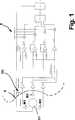
Wieaus dem in
DieElektroden befinden sich räumlich von der restlichen Elektronikabgegrenzt. Sie können z. B. auf einer Leiterplatte alsKupferflächen ausgebildet sein oder als leitende Bereichean einer Kunststoff-Folie ausgeführt sein, die an die Elektronikangeschlossen wird. Die Messelektroden M1, M2, M3 (2, 3, 4 odermehr) sind symmetrisch um die Geberelektrode G1 angeordnet (vgl.Beispiel für 3 Elektroden in
Derfeldstörende Einfluss der Elektronik des Erfassungssystemsund des Gerätes wird durch eine Abschirmung S minimiert.Die Abschirmelektrode S grenzt das Elektrodensystem M1, M2, M3,G1 von der Elektronik E ab. Diese Elektrode S kann z. B. aus einerKunststofffolie mit leitender Beschichtung gefertigt sein.Of thefield disturbing influence of the electronics of the detection systemand the device is minimized by a shield S.The shielding electrode S borders the electrode system M1, M2, M3,G1 from the electronics E off. This electrode S can, for. B. from aPlastic film be made with conductive coating.
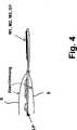
Beispieleder räumlichen Ausführung sind in
Beidem Aufbau nach
DieAbschirmelektrode S wird mit einem Signal beaufschlagt, das sichnur in der Amplitude vom Signal auf der Geberelektrode G1 unterscheidet.Diese Amplitude ist so gewählt, dass die hinter der AbschirmelektrodeS „verborgene” Elektronik vom elektrischen Feldder Geberelektrode G1 „getarnt” ist. Das heißt,das Potential an der Abschirmelektrode S entspricht dem von derGeberelektrode G1 erzeugten Potenzial an der gleicher Stelle imFalle dass die Elektronik und die Abschirmelektrode nicht präsent wären.Das Signal für die Abschirmelektrode kann z. B. mit Hilfeeines (einstellbaren) Spannungsteilers DU aus dem Signal der GeberelektrodeG erzeugt werden.The shielding electrode S is supplied with a signal which differs only in amplitude from the signal on the encoder electrode G1. This amplitude is selected so that the electronics "hidden" behind the shielding electrode S are "camouflaged" by the electric field of the encoder electrode G1. That is, the potential at the shielding electrode S corresponds to the potential generated by the donor electrode G1 in the same place in the event that the electronics and the shielding electrode would not be present. The signal for the shield electrode can, for. B. using a (adjustable) voltage divider DU from the signal of the encoder electrode G are generated.
Dieunvermeidbaren quasistatischen Differenzen der Signale der EmpfangselektrodenM1, M2, M3 werden in der Schaltung elektronisch kompensiert. Dafürwird vorgesehen, dass das gebildete Summensignal mit unterschiedlicherGewichtung an die Verstärker einzelner Kanälezugeführt wird (
DieWirksamkeit der Kompensation wird verbessert wenn die Empfangselektrodenmöglichst gleiche Kopplung zur Geberelektrode aufweisen. DieseKopplung kann z. B. durch zusätzliche Elektroden beeinflusstwerden:
In
In
DieKompensation kann auch während des Betriebs dynamisch nachgestelltwerden, um das Messsystem auf sich eventuell ändernde Einflüsse abzustimmen.TheCompensation can also be dynamically adjusted during operationbe used to tune the measuring system to any changing influences.
Durchdas erfindungsgemäße Konzept wird es möglich,die Gestenerfassungselektronik besonders vorteilhaft unmittelbarin elektronische Geräte, z. B. Mobiltelefone zu integrieren.Weiterhin wird es möglich, die Elektroden unmittelbar indie Leiterplatte zu integrieren, oder als leitende Schicht auf einer Kunststofffolieauszuführen. Zudem wird es möglich, die Anbindungder Elektroden an das Messsystem ohne Koaxialkabel vorzunehmen.Durch das erfindungsgemäße Konzept wird weiterhineine Maximierung der Reichweite des Erfassungssystems bei gegebenenUmgebungseigenschaften erreicht. In vorteilhafter Weise ergibt sichauch eine Linearisierung der Systemantwort auf die Bewegung deszu detektierenden Objektes.Bythe inventive concept makes it possiblethe gesture detection electronics particularly advantageous directlyin electronic devices, eg. B. to integrate mobile phones.Furthermore, it becomes possible to insert the electrodes directly intoto integrate the printed circuit board, or as a conductive layer on a plastic filmperform. In addition, it becomes possible the connectionthe electrodes to the measuring system without coaxial cable.The inventive concept will continuemaximizing the range of the detection system givenEnvironment properties achieved. Advantageously resultsalso a linearization of the system response to the movement of theto be detected object.
ZITATE ENTHALTEN IN DER BESCHREIBUNGQUOTES INCLUDE IN THE DESCRIPTION
Diese Listeder vom Anmelder aufgeführten Dokumente wurde automatisierterzeugt und ist ausschließlich zur besseren Informationdes Lesers aufgenommen. Die Liste ist nicht Bestandteil der deutschenPatent- bzw. Gebrauchsmusteranmeldung. Das DPMA übernimmtkeinerlei Haftung für etwaige Fehler oder Auslassungen.This listThe documents listed by the applicant have been automatedgenerated and is solely for better informationrecorded by the reader. The list is not part of the GermanPatent or utility model application. The DPMA takes overno liability for any errors or omissions.
Zitierte PatentliteraturCited patent literature
- - DE 102007020873[0001]- DE 102007020873[0001]
Claims (10)
Translated fromGermanPriority Applications (8)
| Application Number | Priority Date | Filing Date | Title |
|---|---|---|---|
| DE102008036720ADE102008036720A1 (en) | 2007-04-26 | 2008-08-07 | Sensor device for generating signals indicative of the position or position change of limbs |
| ES09804526.3TES2441869T3 (en) | 2008-08-07 | 2009-08-07 | Sensor device for generating signals that are indicative of position or limb position change |
| JP2011521488AJP5684125B2 (en) | 2008-08-07 | 2009-08-07 | Sensor device for generating signals indicative of limb position or position change |
| KR1020117005167AKR101391171B1 (en) | 2008-08-07 | 2009-08-07 | Sensor device for generating signals that are indicative of the position or change of position of limbs |
| CN200980138720.1ACN102217195B (en) | 2008-08-07 | 2009-08-07 | A sensor device for producing a signal indicative of the position or change in position of an extremity |
| EP09804526.3AEP2364526B1 (en) | 2008-08-07 | 2009-08-07 | Sensor device for generating signals that are indicative of the position or change of position of limbs |
| US12/682,303US8558791B2 (en) | 2008-08-07 | 2009-08-07 | Sensor system for generating signals that are indicative of the position or change of position of limbs |
| PCT/EP2009/005754WO2010015417A2 (en) | 2008-08-07 | 2009-08-07 | Sensor device for generating signals that are indicative of the position or change of position of limbs |
Applications Claiming Priority (2)
| Application Number | Priority Date | Filing Date | Title |
|---|---|---|---|
| DE102007020873ADE102007020873A1 (en) | 2007-04-26 | 2007-04-26 | Sensor device, and methods for generating signals indicative of the position or position change of limbs |
| DE102008036720ADE102008036720A1 (en) | 2007-04-26 | 2008-08-07 | Sensor device for generating signals indicative of the position or position change of limbs |
Publications (1)
| Publication Number | Publication Date |
|---|---|
| DE102008036720A1true DE102008036720A1 (en) | 2011-02-03 |
Family
ID=41664018
Family Applications (1)
| Application Number | Title | Priority Date | Filing Date |
|---|---|---|---|
| DE102008036720ACeasedDE102008036720A1 (en) | 2007-04-26 | 2008-08-07 | Sensor device for generating signals indicative of the position or position change of limbs |
Country Status (8)
| Country | Link |
|---|---|
| US (1) | US8558791B2 (en) |
| EP (1) | EP2364526B1 (en) |
| JP (1) | JP5684125B2 (en) |
| KR (1) | KR101391171B1 (en) |
| CN (1) | CN102217195B (en) |
| DE (1) | DE102008036720A1 (en) |
| ES (1) | ES2441869T3 (en) |
| WO (1) | WO2010015417A2 (en) |
Cited By (1)
| Publication number | Priority date | Publication date | Assignee | Title |
|---|---|---|---|---|
| US10352976B2 (en) | 2013-03-15 | 2019-07-16 | Microchip Technology Incorporated | Matrix electrode design for three-dimensional e-filed sensor |
Families Citing this family (7)
| Publication number | Priority date | Publication date | Assignee | Title |
|---|---|---|---|---|
| DE102008036720A1 (en) | 2007-04-26 | 2011-02-03 | Ident Technology Ag | Sensor device for generating signals indicative of the position or position change of limbs |
| DE102012202365A1 (en) | 2012-02-16 | 2013-08-22 | Schaeffler Technologies AG & Co. KG | Mounting arrangement for pressing rolling bearing inner ring on conical bearing seat surface of shaft, has push plate engaged with inner ring, and bonnet wing nut whose ball screw thread shoots share same axis of rotation with wing nut |
| CN104597795A (en)* | 2015-01-30 | 2015-05-06 | 成都上生活网络科技有限公司 | Non-contact type volume adjusting device and method |
| DE102015202880A1 (en)* | 2015-02-18 | 2016-08-18 | Zircon Corp. | Method and device for detecting an object hidden behind an object |
| EP3178392A1 (en)* | 2015-12-09 | 2017-06-14 | Rythm | Autonomous bioelectric physiological signal acquisition device |
| TWI643113B (en)* | 2017-03-03 | 2018-12-01 | 日商阿爾普士電氣股份有限公司 | Input device and control method thereof |
| CN108414009B (en)* | 2018-02-11 | 2020-10-09 | 梦卓科技(深圳)有限公司 | Structure and method for automatically sensing node position based on partial pressure in replaceable node body sensor network |
Citations (1)
| Publication number | Priority date | Publication date | Assignee | Title |
|---|---|---|---|---|
| DE102007020873A1 (en) | 2007-04-26 | 2008-10-30 | Ident Technology Ag | Sensor device, and methods for generating signals indicative of the position or position change of limbs |
Family Cites Families (10)
| Publication number | Priority date | Publication date | Assignee | Title |
|---|---|---|---|---|
| US4090092A (en)* | 1976-07-16 | 1978-05-16 | General Electric Company | Shielding arrangement for a capacitive touch switch device |
| GB2286247A (en)* | 1994-02-03 | 1995-08-09 | Massachusetts Inst Technology | Capacitive position detection |
| US5844415A (en)* | 1994-02-03 | 1998-12-01 | Massachusetts Institute Of Technology | Method for three-dimensional positions, orientation and mass distribution |
| DE19836054A1 (en)* | 1998-08-10 | 2000-02-17 | Bosch Gmbh Robert | Measurement circuit for capacitive sensor to measure distance or monitor area; has sine wave signal acting on screening electrode and sensor wire connected to input of amplifier acting as current voltage converter across screened cable |
| WO2004059343A1 (en)* | 2002-12-25 | 2004-07-15 | Act Elsi Inc. | Electrostatic capacity detection type proximity sensor |
| DE10323030A1 (en)* | 2003-05-20 | 2004-12-09 | Stefan Reich | Capacitive sensor for multiple applications measures values that influence the capacitance of a measurement space by measuring the capacitive coupling between two electrodes and relating it to a physical value |
| US7777501B2 (en)* | 2005-06-03 | 2010-08-17 | Synaptics Incorporated | Methods and systems for sigma delta capacitance measuring using shared component |
| US8063886B2 (en)* | 2006-07-18 | 2011-11-22 | Iee International Electronics & Engineering S.A. | Data input device |
| DE102008036720A1 (en) | 2007-04-26 | 2011-02-03 | Ident Technology Ag | Sensor device for generating signals indicative of the position or position change of limbs |
| DE202007017303U1 (en) | 2007-08-20 | 2008-04-10 | Ident Technology Ag | computer mouse |
- 2008
- 2008-08-07DEDE102008036720Apatent/DE102008036720A1/ennot_activeCeased
- 2009
- 2009-08-07CNCN200980138720.1Apatent/CN102217195B/ennot_activeExpired - Fee Related
- 2009-08-07USUS12/682,303patent/US8558791B2/ennot_activeExpired - Fee Related
- 2009-08-07EPEP09804526.3Apatent/EP2364526B1/ennot_activeNot-in-force
- 2009-08-07WOPCT/EP2009/005754patent/WO2010015417A2/enactiveApplication Filing
- 2009-08-07JPJP2011521488Apatent/JP5684125B2/ennot_activeExpired - Fee Related
- 2009-08-07KRKR1020117005167Apatent/KR101391171B1/ennot_activeExpired - Fee Related
- 2009-08-07ESES09804526.3Tpatent/ES2441869T3/enactiveActive
Patent Citations (1)
| Publication number | Priority date | Publication date | Assignee | Title |
|---|---|---|---|---|
| DE102007020873A1 (en) | 2007-04-26 | 2008-10-30 | Ident Technology Ag | Sensor device, and methods for generating signals indicative of the position or position change of limbs |
Cited By (1)
| Publication number | Priority date | Publication date | Assignee | Title |
|---|---|---|---|---|
| US10352976B2 (en) | 2013-03-15 | 2019-07-16 | Microchip Technology Incorporated | Matrix electrode design for three-dimensional e-filed sensor |
Also Published As
| Publication number | Publication date |
|---|---|
| KR101391171B1 (en) | 2014-05-02 |
| CN102217195B (en) | 2016-01-20 |
| EP2364526B1 (en) | 2013-10-09 |
| JP2012511188A (en) | 2012-05-17 |
| JP5684125B2 (en) | 2015-03-11 |
| KR20110043737A (en) | 2011-04-27 |
| WO2010015417A2 (en) | 2010-02-11 |
| US8558791B2 (en) | 2013-10-15 |
| WO2010015417A3 (en) | 2011-07-21 |
| ES2441869T3 (en) | 2014-02-06 |
| EP2364526A2 (en) | 2011-09-14 |
| CN102217195A (en) | 2011-10-12 |
| US20120313852A1 (en) | 2012-12-13 |
Similar Documents
| Publication | Publication Date | Title |
|---|---|---|
| DE102008036720A1 (en) | Sensor device for generating signals indicative of the position or position change of limbs | |
| DE102011002447B4 (en) | Capacitive proximity sensor and capacitive proximity detection method | |
| DE112012001000T5 (en) | Capacitive touch detection architecture | |
| DE2819817B2 (en) | Digital coding device with a display device producing visible images | |
| WO1995031701A1 (en) | Measurement device based on a strain gauge, use thereof and modulation amplifier for such measurement devices | |
| EP2494382A1 (en) | Apparatus and method for capacitively recording measured values without errors | |
| DE102011078077A1 (en) | Printed circuit board with electrode configuration of a capacitive sensor | |
| DE102008057823A1 (en) | Capacitive sensor system | |
| DE102011054690A1 (en) | Electrode device for a capacitive sensor device for position detection | |
| DE102007020873A1 (en) | Sensor device, and methods for generating signals indicative of the position or position change of limbs | |
| EP1850096B1 (en) | Remote transmitter for analogue measuring devices | |
| DE102009057931B4 (en) | Circuit arrangement for a capacitive sensor element. | |
| DE102007001712B4 (en) | Arrangement for generating a signal indicative of the presence of an object within an observation area | |
| DE112021005999T5 (en) | Low cost, high measurement speed capacitive sensing circuit for charging mode operation of capacitive sensors | |
| EP0711978B1 (en) | Method and apparatus for determining the current position of a body by capacitive scanning | |
| EP1767917A2 (en) | System and method for locating a leakage on moisture sealing coatings, in particular for building parts | |
| DE102013201704A1 (en) | Capacitive sensor arrangement and capacitive measuring method with compensation of parasitic capacitances | |
| DE102022102893A1 (en) | Sensor device for detecting at least one physical variable | |
| DE112011101944B4 (en) | Capacitive measuring method | |
| DE102021106512A1 (en) | Measuring device, electric motor and method for measuring a shaft voltage of an electric motor | |
| DE102011079174A1 (en) | Position sensing device | |
| DE102011086996A1 (en) | Input element e.g. four-wire resistive touch panel, for e.g. mobile, has Bluetooth antenna integrated and/or embedded in input element main surface, and controlled by supply line, which is electrically insulated from reading line | |
| WO2001003054A1 (en) | Method for controlling a display in a mobile device | |
| WO2013182342A1 (en) | Capacitive sensor arrangement and touch-sensitive screen having a capacitive sensor arrangement | |
| DE102017213548A1 (en) | Capacitive proximity switch device |
Legal Events
| Date | Code | Title | Description |
|---|---|---|---|
| AF | Is addition to no. | Ref document number:102007020873 Country of ref document:DE Kind code of ref document:P | |
| R082 | Change of representative | Representative=s name:BETTINGER SCHNEIDER SCHRAMM PATENT- UND RECHTS, DE Representative=s name:2S-IP SCHRAMM SCHNEIDER PATENTANWAELTE - RECHT, DE Representative=s name:2S-IP SCHRAMM SCHNEIDER BERTAGNOLL PATENT- UND, DE | |
| R012 | Request for examination validly filed | Effective date:20140428 | |
| R082 | Change of representative | Representative=s name:2S-IP SCHRAMM SCHNEIDER PATENTANWAELTE - RECHT, DE Representative=s name:2S-IP SCHRAMM SCHNEIDER BERTAGNOLL PATENT- UND, DE | |
| R016 | Response to examination communication | ||
| R016 | Response to examination communication | ||
| R081 | Change of applicant/patentee | Owner name:NEODRON LTD., IE Free format text:FORMER OWNER: IDENT TECHNOLOGY AG, 82234 WESSLING, DE Owner name:MICROCHIP TECHNOLOGY GERMANY GMBH, DE Free format text:FORMER OWNER: IDENT TECHNOLOGY AG, 82234 WESSLING, DE | |
| R082 | Change of representative | Representative=s name:PETERREINS SCHLEY PATENT- UND RECHTSANWAELTE, DE Representative=s name:PETERREINS SCHLEY PATENT- UND RECHTSANWAELTE P, DE Representative=s name:2S-IP SCHRAMM SCHNEIDER PATENTANWAELTE - RECHT, DE Representative=s name:2S-IP SCHRAMM SCHNEIDER BERTAGNOLL PATENT- UND, DE | |
| R081 | Change of applicant/patentee | Owner name:NEODRON LTD., IE Free format text:FORMER OWNER: MICROCHIP TECHNOLOGY GERMANY GMBH, 82205 GILCHING, DE | |
| R082 | Change of representative | Representative=s name:PETERREINS SCHLEY PATENT- UND RECHTSANWAELTE, DE Representative=s name:PETERREINS SCHLEY PATENT- UND RECHTSANWAELTE P, DE | |
| R079 | Amendment of ipc main class | Free format text:PREVIOUS MAIN CLASS: G01V0003120000 Ipc:G01V0003080000 | |
| R002 | Refusal decision in examination/registration proceedings | ||
| R003 | Refusal decision now final |