DE102008034304B4 - imaging device - Google Patents
imaging deviceDownload PDFInfo
- Publication number
- DE102008034304B4 DE102008034304B4DE102008034304.8ADE102008034304ADE102008034304B4DE 102008034304 B4DE102008034304 B4DE 102008034304B4DE 102008034304 ADE102008034304 ADE 102008034304ADE 102008034304 B4DE102008034304 B4DE 102008034304B4
- Authority
- DE
- Germany
- Prior art keywords
- feature point
- lane
- detection
- line
- pixels
- Prior art date
- Legal status (The legal status is an assumption and is not a legal conclusion. Google has not performed a legal analysis and makes no representation as to the accuracy of the status listed.)
- Active
Links
Images


Classifications
- G—PHYSICS
- G06—COMPUTING OR CALCULATING; COUNTING
- G06V—IMAGE OR VIDEO RECOGNITION OR UNDERSTANDING
- G06V20/00—Scenes; Scene-specific elements
- G06V20/50—Context or environment of the image
- G06V20/56—Context or environment of the image exterior to a vehicle by using sensors mounted on the vehicle
- G06V20/588—Recognition of the road, e.g. of lane markings; Recognition of the vehicle driving pattern in relation to the road
- G—PHYSICS
- G06—COMPUTING OR CALCULATING; COUNTING
- G06V—IMAGE OR VIDEO RECOGNITION OR UNDERSTANDING
- G06V20/00—Scenes; Scene-specific elements
- G06V20/50—Context or environment of the image
- G06V20/56—Context or environment of the image exterior to a vehicle by using sensors mounted on the vehicle
- G06V20/58—Recognition of moving objects or obstacles, e.g. vehicles or pedestrians; Recognition of traffic objects, e.g. traffic signs, traffic lights or roads
Landscapes
- Engineering & Computer Science (AREA)
- Physics & Mathematics (AREA)
- General Physics & Mathematics (AREA)
- Multimedia (AREA)
- Theoretical Computer Science (AREA)
- Image Analysis (AREA)
- Traffic Control Systems (AREA)
- Image Processing (AREA)
Abstract
Translated fromGermanDescription
Translated fromGerman1. Erfindungsgebiet1. Field of Invention
Die vorliegende Erfindung betrifft ein Bildverarbeitungsgerät, das so gestaltet ist, dass es ein Bild eines Blicks nach vorne aus einem Fahrzeug aufnimmt.The present invention relates to an image processing apparatus designed to capture an image of a forward view of a vehicle.
2. Beschreibung des Standes der Technik2. Description of the Prior Art
Es sind Bildverarbeitungsgeräte entwickelt worden, die in Fahrzeugen installiert sind. Solche Geräte können bei automatischen Fahrtechniken angewandt werden. Für ein bildverarbeitendes Gerät sind die folgenden drei Charakteristika erforderlich.Image processing devices installed in vehicles have been developed. Such devices can be applied to automated driving techniques. The following three characteristics are required for an image processing apparatus.
Um die Fahrbahn, auf der das Fahrzeug fährt, zu erkennen, ist es erstens notwendig, ein Bild von der Frontsicht aus dem Fahrzeug durch eine Kamera, wie beispielsweise den CCD-(ladungsgekoppelte Vorrichtung)- oder den CMOS-(Komplementär-Metalloxidhalbleiter)-Bildsensor aufzunehmen und eine Verarbeitung des Bildes in Echtzeit durchzuführen.First, in order to recognize the roadway on which the vehicle is running, it is necessary to obtain an image of the front view from the vehicle through a camera such as the CCD (Charge Coupled Device) or the CMOS (Complementary Metal Oxide Semiconductor) Record image sensor and perform real-time processing of the image.
Zweitens ist für das sichere Fahren ein korrektes Erkennen der Fahrbahn erforderlich. Daher ist es erforderlich, dass die eingegebenen Bilddaten der Fahrbahn ein Merkmal haben, das bei der Bilderkennung einen geringeren Fehler hervorbringt.Secondly, correct recognition of the lane is required for safe driving. Therefore, the input image data of the road is required to have a feature that causes less error in image recognition.
Drittens ist es erforderlich, aus dem Bild der Frontsicht Information über die Kanten der Fahrbahnmarkierung zu extrahieren, die auf der Oberfläche der Fahrbahn aufgemalt ist. In einer derartigen Information ist beispielsweise die Position einer Fahrbahntrennlinie auf der Fahrbahnoberfläche, die Anwesenheit oder Abwesenheit einer Abzweigung der Fahrbahn oder die Anwesenheit oder Abwesenheit einer Sackgasse oder eines Hindernisses repräsentiert.Third, it is necessary to extract information on the edges of the lane marking painted on the surface of the lane from the front view image. Such information represents, for example, the position of a lane division line on the lane surface, the presence or absence of a fork in the lane, or the presence or absence of a dead end or an obstacle.
Es werden einige Beispiele von Bildverarbeitungsgeräten für Fahrzeuge vorgestellt.Some examples of image processing devices for vehicles are presented.
Die offengelegte japanische Patentanmeldung
Die japanische Patentveröffentlichung
ZUSAMMENFASSUNGSUMMARY
In den vorstehend ausgeführten Bildverarbeitungsgeräten für Fahrzeuge (insbesondere Weiße-Linien-Erkennungsgeräte) sind für das Erfassen der Fahrbahntrennlinie, der Abzweigung, der Sackgasse und des Hindernisses festliegende Muster zum Erfassen derselben vorbereitet, und der gesamte Bereich des Bildes wird zum Überprüfen der Übereinstimmung des Bildes mit den Mustern gescannt. Da in diesem Fall der gesamte Bereich gescannt wird, besteht das Problem, dass die Anzahl der Verarbeitungsschritte des Scannens entsprechend der Ganzbildgröße des Bildes groß wird.In the above-mentioned image processing devices for vehicles (particularly white line recognition devices), for detecting the lane division line, the junction, the dead end and the obstacle, fixed patterns are prepared for detecting the same, and the entire area of the image is used to check the consistency of the image scanned with the patterns. In this case, since the entire area is scanned, there is a problem that the number of processing steps of scanning becomes large according to the frame size of the image.
Eine Aufgabe der vorliegenden Erfindung ist es deshalb, vor dem Hintergrund der voranstehend genannten Probleme ein verbessertes Bildverarbeitungsgerät bereitzustellen, bei dem insbesondere die Anzahl der Verarbeitungsschritte vermindert werden kann.It is therefore an object of the present invention, against the background of the above problems, to provide an improved image processing apparatus in which, in particular, the number of processing steps can be reduced.
Gemäß der vorliegenden Erfindung wird ein Bildverarbeitungsgerät gemäß dem Hauptanspruch offenbart. Des Weiteren wird ein eingebautes Bildverarbeitungsgerät für Fahrzeuge gemäß Anspruch 2 offenbart.According to the present invention there is disclosed an image processing apparatus as set out in the main claim. Furthermore, an on-vehicle image processing apparatus according to
Wie vorstehend angegeben, ist in einem eingebauten Bildverarbeitungsgerät für Fahrzeuge (M100) gemäß einer Ausführungsform der vorliegenden Erfindung jedem der Merkmalspunkte (einer Fahrbahntrennlinie, einer Abzweigung, einer Sackgasse oder einem Hindernis) der Straße eine Scannregion zugewiesen, die für Erfassungsbilddaten (Bilddaten zur Erfassung von Merkmalspunkten) gesetzt ist. Somit kann die Anzahl der Schritte des Bildscannvorgangs reduziert werden.As stated above, in an on-vehicle image processing apparatus (M100) according to an embodiment of the present invention, each of feature points (a lane division line, a junction, a dead end, or an obstacle) of the road is assigned a scanning region used for detection image data (image data for detecting feature points) is set. Thus, the number of steps in the image scanning process can be reduced.
In einem eingebauten Bildverarbeitungsgerät für Fahrzeuge (M100) gemäß einer Ausführungsform der vorliegenden Erfindung wird die Eigenschaft des Bildes, nämlich die Perspektive, bei der der Vordergrund groß und der Hintergrund klein erscheint, zum Bestimmen der jeweiligen Scannregionen entsprechend den Arten der auf einer Straße zu erfassenden Ziele bestimmt. Somit ist es möglich, den Einfluss von Rauschen in dem Scannbereich zu reduzieren, sodass es möglich ist, Fehler bei dem Erfassen der Merkmalspunkte auf der Straße zu reduzieren.In an on-vehicle image processing apparatus (M100) according to an embodiment of the present invention, the property of the image, namely the perspective in which the foreground appears large and the background appears small, is used to determine the respective scanning regions corresponding to the types of road to be detected goals determined. Thus, it is possible to reduce the influence of noise in the scanning area, so it is possible to reduce errors in detecting the feature points on the road.
In einem eingebauten Bildverarbeitungsgerät für Fahrzeuge (M100) gemäß einer Ausführungsform der vorliegenden Erfindung ist auch eine Fahrbahntrennlinienerfassungs-Scannregion (A101) im Vordergrund (der unteren Seite der Bildregion) gesetzt. Selbst wenn die Fahrzeugposition von der Fahrbahn abweicht oder wenn das Fahrzeug durch eine Kurve fährt, kann somit die Fahrbahntrennlinie wenigstens teilweise abgebildet werden. Daher wird es selbst in solchen Fällen einfach, den Vorgang zum Berechnen der Fahrzeugposition durchzuführen.In an on-vehicle image processing apparatus (M100) according to an embodiment of the present invention, a lane division line detection scanning region (A101) is also set in the foreground (the lower side of the image region). Thus, even when the vehicle position deviates from the lane or when the vehicle is cornering, the lane dividing line can be imaged at least partially. Therefore, even in such cases, it becomes easy to perform the vehicle position calculation process.
In einem eingebauten Bildverarbeitungsgerät für Fahrzeuge (M100) gemäß einer Ausführungsform der vorliegenden Erfindung ist auch der Hintergrund in dem Bild als die Sackgassen- und Hinderniserfassungs-Scannregion gesetzt. Daher kann das Vorhandensein oder die Abwesenheit einer Sackgasse oder eines Hindernisses früher als das Erfassen der Abzweigung erfasst werden. Somit wird es einfach, die Entscheidung, wie beispielsweise eine Geschwindigkeitssteuerung, eine Richtungssteuerung und dergleichen durchzuführen, wenn das Ausgabegerät (M200) das Fahren des Fahrzeugs steuert.In an on-vehicle image processing apparatus (M100) according to an embodiment of the present invention, the background in the image is also set as the dead end and obstacle detection scanning region. Therefore, the presence or absence of a dead end or an obstacle can be detected earlier than detection of the intersection. Thus, when the output device (M200) controls running of the vehicle, it becomes easy to perform the decision such as speed control, direction control and the like.
Figurenlistecharacter list
Die vorstehenden und weitere Aufgaben, Vorteile und Merkmale der vorliegenden Erfindung gehen aus der folgenden Beschreibung gewisser bevorzugter Ausführungsformen anhand der begleitenden Zeichnungen im Einzelnen hervor, in welchen zeigt:
1 eine Konfiguration eines eingebauten Bildverarbeitungsgeräts für Fahrzeuge;2A ein Flussdiagramm, das die Funktionsweise eines eingebauten Bildverarbeitungsgeräts für Fahrzeuge zeigt;2B ein Flussdiagramm, das die Funktionsweise eines eingebauten Bildverarbeitungsgeräts für Fahrzeuge zeigt;2C ein Flussdiagramm, das die Funktionsweise eines eingebauten Bildverarbeitungsgeräts für Fahrzeuge zeigt;2D ein Flussdiagramm, das die Funktionsweise eines eingebauten Bildverarbeitungsgeräts für Fahrzeuge zeigt;3A eine Ansicht eines zweidimensionalen Raumfilters (Glättungsfilter), das bei einer Operation eines eingebauten Bildverarbeitungsgeräts für Fahrzeuge verwendet wird;3B eine Ansicht eines zweidimensionalen Raumfilters (Laplace-Glättungsfilter), das bei einer Operation eines eingebauten Bildverarbeitungsgeräts für Fahrzeuge verwendet wird;4A eine Ansicht, die das Erfassen eines Fahrbahntrennlinienmerkmalspunkts als eine Operation eines eingebauten Bildverarbeitungsgeräts für Fahrzeuge zeigt;4B eine Ansicht, die das Erfassen eines Fahrbahntrennlinienmerkmalspunkts als eine Operation eines eingebauten Bildverarbeitungsgeräts für Fahrzeuge zeigt;5 eine Ansicht, die eine Operation eines eingebauten Bildverarbeitungsgeräts für Fahrzeuge beschreibt, die eine Fahrbahntrennlinienerfassungs-Scannregion A101, eine Abzweigungserfassungs-Scannregion A102 und eine Sackgassen- und Hinderniserfassungs-Scannregion A103 von Merkmalspunkt-Erfassungsbilddaten zeigt;6 eine Ansicht, die das Berechnen einer laufenden Fahrzeugposition als eine Operation eines eingebauten Bildverarbeitungsgeräts für Fahrzeuge beschreibt;7A eine Ansicht, die eine Wirkung beschreibt, wenn der Schritt S112 durchgeführt wird;7B eine Ansicht, die eine Wirkung beschreibt, wenn der Schritt S112 durchgeführt wird; und7C eine Ansicht, die eine Wirkung beschreibt, wenn der Schritt S112 durchgeführt wird.
1 a configuration of an on-vehicle image processing apparatus;2A Fig. 12 is a flow chart showing the operation of an on-vehicle image processing apparatus;2 B Fig. 12 is a flow chart showing the operation of an on-vehicle image processing apparatus;2C Fig. 12 is a flow chart showing the operation of an on-vehicle image processing apparatus;2D Fig. 12 is a flow chart showing the operation of an on-vehicle image processing apparatus;3A Fig. 14 is a view of a two-dimensional spatial filter (smoothing filter) used in an operation of an on-vehicle image processing apparatus;3B Fig. 14 is a view of a two-dimensional spatial filter (Laplacian smoothing filter) used in an operation of an on-vehicle image processing apparatus;4A 12 is a view showing detection of a lane-dividing line feature point as an operation of an on-vehicle image processing apparatus;4B 12 is a view showing detection of a lane-dividing line feature point as an operation of an on-vehicle image processing apparatus;5 12 is a view describing an operation of an on-vehicle image processing apparatus showing a lane-dividing-line detection scan region A101, an intersection detection scan region A102, and a dead end and obstacle detection scan region A103 of feature point detection image data;6 Fig. 14 is a view describing calculation of a current vehicle position as an operation of an on-vehicle image processing apparatus;7A Fig. 12 is a view describing an effect when step S112 is performed;7B Fig. 12 is a view describing an effect when step S112 is performed; and7C 12 is a view describing an effect when step S112 is performed.
BESCHREIBUNG DER BEVORZUGTEN AUSFÜHRUNGSFORMENDESCRIPTION OF THE PREFERRED EMBODIMENTS
Im Folgenden wird ein eingebautes Bildverarbeitungsgerät für Fahrzeuge gemäß der Ausführungsformen der vorliegenden Erfindung anhand der anhängenden Zeichnungen beschrieben.Hereinafter, an on-vehicle image processing apparatus according to embodiments of the present invention will be described with reference to the accompanying drawings.
[Konfiguration][Configuration]
Das Abbildungsgerät M101 hat eine Kamera, wie beispielsweise eine CCD oder einen CMOS-Bildsensor, und ist in der Blickrichtung nach vorne eingestellt. Der A/D-Wandler M102 ist mit dem Abbildungsgerät M101 und dem Bildverarbeitungsgerät M110 verbunden. Das Bildverarbeitungsgerät M110 ist ein Computer und ist durch eine Hardware, beispielsweise eine Elektronikschaltung, und eine Software, beispielsweise ein Computerprogramm, realisiert.The imaging device M101 has a camera such as a CCD or a CMOS image sensor and is set in the forward viewing direction. The A/D converter M102 is connected to the imaging device M101 and the image processing device M110. The image processing apparatus M110 is a computer and is implemented by hardware such as an electronic circuit and software such as a computer program.
Das Bildverarbeitungsgerät M110 enthält einen Speicher M103, eine Kantenerfassungssektion M104, eine Kantenkorrektur- und Rauschreduktionssektion M105 und eine Merkmalspunkt-Erfassungssektion M111. Die Merkmalspunkt-Erfassungssektion M111 enthält eine Fahrbahntrennlinien-Erfassungssektion M106, eine Abzweigungserfassungssektion M 107, eine Sackgassen- und Hinderniserfassungssektion M108 und eine Fahrzeugpositions-Schätzsektion M109. Der Speicher M103 ist mit dem A/D-Wandler M102 und der Kantenerfassungssektion M104 verbunden. Die Kantenerfassungssektion M104 ist mit der Kantenkorrektur- und Rauschreduktionssektion M105 verbunden. Die Kantenkorrektur- und Rauschreduktionssektion M105 ist mit der Fahrbahntrennlinien-Erfassungssektion M106, der Abzweigungserfassungssektion M107 und der Sackgassen- und Hinderniserfassungssektion M108 verbunden. Die Fahrbahntrennlinien-Erfassungssektion M106 ist mit der Fahrzeugpositions-Schätzsektion M109 verbunden. Die Fahrzeugpositions-Schätzsektion M109, die Abzweigungserfassungssektion M107 und die Sackgassen- und Hinderniserfassungssektion M108 sind mit einem Ausgabegerät wie beispielsweise einem automatischen Fahrsystem M200 verbunden.The image processing device M110 includes a memory M103, an edge detection section M104, an edge correction and noise reduction section M105, and a feature point detection section M111. The feature point detection section M111 includes a lane division line detection section M106, an intersection detection section M107, a dead end and obstacle detection section M108, and a vehicle position estimation section M109. The memory M103 is connected to the A/D converter M102 and the edge detection section M104. The edge detection section M104 is connected to the edge correction and noise reduction section M105. The edge correction and noise reduction section M105 is connected to the lane dividing line detection section M106, the intersection detection section M107, and the dead end and obstacle detection section M108. The lane division line detecting section M106 is connected to the vehicle position estimating section M109. The vehicle position estimation section M109, the intersection detection section M107, and the dead end and obstacle detection section M108 are connected to an output device such as an automatic driving system M200.
[Funktionsweise][Functionality]
Die
Das Abbildungsgerät M101 nimmt ein Bild des Blicks nach vorne aus dem Fahrzeug auf eine Straße unter Verwendung einer Kamera auf und erzeugt analoge Bilddaten, die das Bild vor dem Fahrzeug aus dem Fahrzeug gesehen repräsentieren. Der A/D-Wandler M102 führt eine Analog/Digital-Wandlung an den analogen Bilddaten durch, um digitale Bilddaten zu erzeugen und speichert die digitalen Bilddaten in dem Speicher M103 (Schritt S101). Diese digitalen Bilddaten enthalten Pixeldaten entsprechend den Pixeln, die in einer Matrix von m Zeilen und n Spalten angeordnet sind, die den Blick aus dem Fahrzeug nach vorne repräsentieren. Hierbei sind m und n ganze Zahlen von 3 oder größer.The imaging device M101 captures an image of a road ahead of the vehicle using a camera, and generates analog image data representing the image in front of the vehicle seen from the vehicle. The A/D converter M102 performs analog-to-digital conversion on the analog image data to generate digital image data and stores the digital image data in the memory M103 (step S101). This digital image data includes pixel data corresponding to the pixels arranged in a matrix of m rows and n columns representing the forward view of the vehicle. Here, m and n are integers of 3 or more.
Die Kantenerfassungssektion M104 erzeugt zweidimensional gefilterte Bilddaten mittels Durchführen eines zweidimensionalen Filterungsvorgangs an den m Zeilen- und n Spaltenpixeln der in dem Speicher M103 gespeicherten digitalen Bilddaten.The edge detection section M104 generates two-dimensionally filtered image data by performing a two-dimensional filtering process on the m row and n column pixels of the digital image data stored in the memory M103.
In dem „zweidimensionalen Raumfilter“ wird der Filterungsvorgang an einem fokussierten Pixel auf der Grundlage der Information eines gewissen zweidimensionalen Bereichs, der das fokussierte Pixel auf dem Bild umgibt, durchgeführt. In dieser Ausführungsform ist in dem zweidimensionalen Filterungsvorgang ein Quadrat oder ein Rechteck, welches einen Bereich umgibt (Umfang) für jedes der Pixel g(i, j) gesetzt. Dann wird für jedes der Pixel in dem umgebenden Bereich für jedes der Pixel eine Gewichtung vorab gesetzt. Der gewichtete Mittelwert der Intensität des umgebenden Bereichs wird für jedes der Pixel in den gesamten Bildern als die gefilterte (erneut berechnete oder der Mittelwert) Intensität des mittleren Pixels f(i, j) berechnet. Für den Fall, dass beispielsweise der umgebende Bereich auf einen 3 × 3-Quadratbereich gesetzt ist, wird die mittlere Intensität f(i, j) durch die Mittelwertbildung der Intensitäten der 9 Pixel g(i-1, j-1), g(i, j-1), g(i+1, j-1), g(i-1, j), g(i, j), g(i+1, j), g(i-1, j+1), g(i, j+1) und g(i+1, j+1) mit ihren jeweiligen Gewichtungen berechnet. Wenn das Bild ein Farbbild ist, wird diese Mittelwertbildung für jede der Farbkomponenten der Pixel für jede der m Zeilen und n Spalten von Pixeln der digitalen Bilddaten durchgeführt.In the "two-dimensional spatial filter", the filtering process is performed on a focused pixel based on the information of a certain two-dimensional area surrounding the focused pixel on the image. In this embodiment, in the two-dimensional filtering process, a square or a rectangle surrounding an area (perimeter) is set for each of the pixels g(i, j). Then, for each of the pixels in the surrounding area, a weight is preset for each of the pixels. The weighted mean of the intensity of the surrounding area is calculated for each of the pixels in the entire images as the filtered (recalculated or the mean) intensity of the center pixel f(i,j). For example, in the case that the surrounding area is set to a 3 × 3 square area, the average intensity f(i, j) is obtained by averaging the intensities of the 9 pixels g(i-1, j-1), g( i, j-1), g(i+1, j-1), g(i-1, j), g(i, j), g(i+1, j), g(i-1, j +1), g(i, j+1) and g(i+1, j+1) are calculated with their respective weights. If the image is a color image, this averaging is performed for each of the color components of the pixels for each of the m rows and n columns of pixels of the digital image data.
Wenn hierbei i und j ganze Zahlen sind, die die Bedingung erfüllen 2 ≦ i ≦ (m-1) bzw. 2 ≦ j ≦ (n-1), wird die mittlere Intensität f(i, j) durch die folgende Gleichung (1) repräsentiert.
Hierbei ist M (i, j) eine Raumfilterkoeffizientmatrix, die als eine Tabelle der Gewichtungen in dem Umfangsbereich für jedes der Pixel funktioniert und die Suffixe zeigen die Position jedes Elements dieser Matrix an. Die Matrix M wird durch die folgende Gleichung (2) repräsentiert.
Durch Setzen verschiedener Gewichtungen in der Raumfilterkoeffizientenmatrix M (i, j) können verschiedene Arten von Filterung erzielt werden. Als solche zweidimensionale Filterungsvorgänge werden beispielsweise Glättungsfiltervorgänge (Schritt S 102) und der Laplace-Filterungsvorgang (auch als Laplace-Glättungsfiltervorgang bezeichnet) (Schritt S103), bei dem beispielsweise die 3 × 3-Maskenfilter, die in den
Zunächst wird in dem Glättungsfiltervorgang (auch als einfacher Glättungsfiltervorgang bezeichnet) die mittlere Intensität f(i, j) berechnet durch: f(i, j) = f 1 × g(i-1, j-1) + 1 × g(i, j-1) + 1 × g(i+1, j-1) + 1 × g(i-1, j) + 1 × g(i, j) + 1 × g(i+1, j) + 1 × g(i-1, j+1) + 1 × g(i, j+1) + 1 × g(i+1, j+1)} / 9.First, in the smoothing filter process (also referred to as simple smoothing filter process), the mean intensity f(i,j) is calculated by: f(i,j) =
Die Koeffizienten, die vor jedem Wert g(x, y) liegen, sind durch die folgende Gleichung (3) in der Form der Raumfilterkoeffizientenmatrix M (i, j) repräsentiert.
Als Nächstes bestimmt der Laplace-Filterungsvorgang die Differenz zwischen der Intensität f (i, j), repräsentiert durch das fokussierte Pixel g (i, j), und den Intensitäten f (i-1, j-1), f (i, j-1), f (i+1, j-1), f (i-1, j), f (i+1, j), f (i-1, j+1), f (i, j+1) und f (i+1, j+1), die durch die 8 umgebenden Pixel g (i-1, j-1), g (i, j-1), g (i+1, j-1), g (i-1, j), g (i+1, j), g (i-1, j+1), g (i, j+1) bzw. g (i+1, j+1) repräsentiert sind, welche die Pixel um das fokussierte Pixel sind. Zu diesem Zeitpunkt wird die Raumfilterkoeffizientenmatrix M (i, j) durch die Gleichung (4) repräsentiert.
Die Kantenerfassungssektion M104 führt einen Binarisierungsvorgang an den m Zeilen- und den n Spaltenpixeln der zweidimensional gefilterten Bilddaten durch, um in die Binärform gebrachte Bilddaten zu erzeugen (Schritt S104).The edge detection section M104 performs a binarization process on the m-row and the n-column pixels of the two-dimensionally filtered image data to generate binarized image data (step S104).
In diesem Binarisierungsvorgang wird der erste Wert und der zweite Wert, beispielsweise „1" und „0“, der eine binäre Ziffer bildet, gesetzt. Es wird „1" oder „0“ gesetzt, um die binäre Zahl entsprechend Schwarz anzuzeigen, wenn die berechnete Intensität jeder der m Zeilen- und n Spaltenpixel der zweidimensional gefilterten Bilddaten unter einem vorbestimmten Schwellwert ist, und es wird der andere Wert von „1“ oder „0“ gesetzt, um die binäre Zahl entsprechend Weiß anzuzeigen, wenn die berechnete Intensität jedes derselben oberhalb des vorbestimmten Schwellwerts ist. Als Ergebnis werden die in binäre Form gebrachten Bilddaten, zusammengesetzt aus Pixeln, die jeweils entweder den Wert „1“ oder „0“ haben, erzeugt. Die Kantenerfassungssektion M104 gibt die in die Binärform gebrachten Bilddaten an die Kantenkorrektur- und Rauschreduktionssektion M105 als Rauscherfassungsbilddaten.In this binarization process, the first value and the second value such as "1" and "0" constituting a binary digit are set. "1" or "0" is set to display the binary number correspondingly black when the calculated intensity of each of the m row and n column pixels of the two-dimensionally filtered image data is below a predetermined threshold, and the other of "1" or "0" is set to indicate the binary number corresponding to white when the calculated intensity of each of them is above the predetermined threshold. As a result, the image data brought into binary form, composed of pixels each having either the value "1" or "0", is generated. The edge detection section M104 outputs the binarized image data to the edge correction and noise reduction section M105 as noise detection image data.
Die Kantenkorrektur- und Rauschreduktionssektion M105 erzeugt Merkmalpunkt-Erfassungsbilddaten, indem sie eine Kantenkorrektur und eine Rauschreduktion an den m Zeilen- und n Spaltenpixeln der Rauscherfassungsbilddaten durchführt (Schritt S105).The edge correction and noise reduction section M105 generates feature point detection image data by performing edge correction and noise reduction on the m row and n column pixels of the noise detection image data (step S105).
In diesem Kantenkorrektur- und Rauschreduktionsvorgang wird jede der Anzahl von Binärzahlen „0“ und „1", die durch die umgebenden Pixel um das fokussierte Pixel repräsentiert ist, für jede der m Zeilen- und n Spaltenpixel der Rauscherfassungsbilddaten gezählt. Und dann wird die Binärzahl jedes der Pixel durch eine neue Binärzahl in Übereinstimmung mit der Zahl, die durch Zählen von „0“ und „1“ um das Pixel, das Verhältnis von der Anzahl von „0“-Pixeln zu „1“-Pixeln und das Übereinstimmungsergebnis der Anordnung der „0“- und „1"-Pixel mit dem vorab gesetzten Muster erzielt worden ist, ausgetauscht. Dieser Vorgang wird an allen Pixeln durchgeführt.In this edge correction and noise reduction process, each of the number of binary numbers "0" and "1" represented by the surrounding pixels around the focused pixel is counted for each of the m row and n column pixels of the noise detection image data. And then the binary number each of the pixels by a new binary number in accordance with the number obtained by counting "0" and "1" around the pixel, the ratio of the number of "0" pixels to "1" pixels, and the alignment result the "0" and "1" pixels have been obtained with the preset pattern are exchanged. This process is performed on all pixels.
Was einen solchen Zustand betrifft, können die folgenden drei Punkte veranschaulicht werden.Regarding such a state, the following three points can be illustrated.
Zustand 1: Wenn die Binärzahl, welche durch das fokussierte Pixel repräsentiert ist, Schwarz „1“ ist und wenn 4 Pixel oder mehr unter den umgebenden Pixeln die Binärzahl haben, welche Weiß „0“ repräsentiert, wird die Binärzahl, welche von dem fokussierten Pixel repräsentiert ist, von Schwarz „1“ in Weiß „0“ geändert.State 1: When the binary number represented by the focused pixel is black "1" and when 4 pixels or more among the surrounding pixels have the binary number representing white "0". sent, the binary number represented by the focused pixel is changed from black "1" to white "0".
Zustand 2: Wenn die Binärzahl, welche von dem fokussierten Pixel repräsentiert ist, Weiß „0“ oder Schwarz „1“ ist und wenn ein, zwei oder drei Pixel von den umgebenden Pixeln die Binärzahl haben, welche Weiß „0“ repräsentiert, wird die Binärzahl des fokussierten Pixels auf dem aktuellen Wert gehalten.State 2: If the binary number represented by the focused pixel is white "0" or black "1" and if one, two or three pixels out of the surrounding pixels have the binary number representing white "0", the Binary number of focused pixel kept at current value.
Zustand 3: Wenn die Binärzahl, welche durch das fokussierte Pixel repräsentiert wird, Weiß „0“ oder Schwarz „1“ ist und wenn alle umgebenden Pixel die Schwarz repräsentierende Binärzahl „1“ haben, wird die durch das fokussierte Pixel repräsentierte Binärzahl durch Schwarz „1“ ersetzt.State 3: If the binary number represented by the focused pixel is white "0" or black "1" and if all surrounding pixels have the binary number "1" representing black, the binary number represented by the focused pixel is represented by black " 1" replaced.
Der vorstehende Zustand ist ein Beispiel, und es können andere Arten von Zuständen für den Kantenkorrektur- und Rauschreduktionsvorgang verwendet werden.The above state is an example, and other types of states can be used for the edge correction and noise reduction process.
Bezüglich der Merkmalspunkt-Erfassungsbilddaten, die durch die Vorgänge in den Schritten S102 bis S105 erzielt werden, wird verglichen mit den digitalen Bilddaten, die im Schritt S101 erzielt werden deren Kontrast verstärkt und das Rauschen unterdrückt. Da der Kontrast verstärkt ist, ist die Kante verstärkt, was es ermöglicht, dass der Merkmalspunkt auf der Straße leicht zu extrahieren ist. Die Kantenkorrektur- und Rauschreduktionssektion M105 gibt die Merkmalspunkt-Erfassungsbilddaten an die Merkmalspunkt-Erfassungssektion M111 aus.As for the feature point detection image data obtained through the operations in steps S102 to S105, compared with the digital image data obtained in step S101, its contrast is enhanced and noise is suppressed. As the contrast is enhanced, the edge is enhanced, allowing the feature point on the road to be easily extracted. The edge correction and noise reduction section M105 outputs the feature point detection image data to the feature point detection section M111.
Die Merkmalspunkt-Erfassungssektion M111 scannt m Zeilen und n Spaltenpixel der Merkmalspunkt-Erfassungsbilddaten jeweils eine Zeile auf einmal als Scannzeile und erfasst die Pixel, die die Binärzahl „1“ haben, welche Schwarz repräsentieren, aus den m Zeilen und n Spalten der Pixel und erfasst Merkmalspunkte der Fahrbahn in Übereinstimmung mit den Pixeln, welche Schwarz „1“ repräsentieren. In dem Fall einer weißen Linie beispielsweise wie in der
Der Merkmalspunkt ist in einer Anzahl von Arten kategorisiert, die veranschaulicht sind durch: einen Fahrbahntrennlinienmerkmalspunkt, der eine Linie repräsentiert, die auf eine Straßenoberfläche gemalt ist, um benachbarte Fahrspuren zu trennen, typischerweise eine weiße Linie; einen Abzweigungsmerkmalspunkt, der eine Abzweigung von der Straße repräsentiert; und einen Sackgassen- und Hindernismerkmalspunkt, der repräsentiert, dass die Straße in eine Sackgasse führt oder die Straße durch ein Hindernis blockiert ist.The feature point is categorized in a number of ways, illustrated by: a lane division line feature point, which represents a line painted on a road surface to separate adjacent lanes of traffic, typically a white line; a junction feature point representing a junction from the road; and a dead end and obstacle feature point representing that the road leads to a dead end or the road is blocked by an obstacle.
Bei der Erläuterung der Ausführungsformen der vorliegenden Erfindung können anstatt der Fahrbahntrennlinie, die typischerweise eine weiße Linie ist, andere Arten von Fahrbahnmarkierungen auf die gleiche Weise verarbeitet werden. Solche Fahrbahnmarkierungen umfassen eine gelbe Linie, die repräsentieren, dass die Fahrzeugspur eine Überholverbotszone ist, und Zeichen, die eine Verkehrsregel repräsentieren, wie beispielsweise eine zulässige Geschwindigkeit, eine Wegrichtung und dergleichen.In explaining the embodiments of the present invention, instead of the lane division line, which is typically a white line, other types of lane markings can be processed in the same way. Such lane markings include a yellow line representing that the vehicle lane is a no-passing zone, and characters representing a traffic rule such as a speed limit, a direction of travel, and the like.
Die Merkmalspunkt-Erfassungssektion M111 scannt die m Zeilen und n Spaltenpixel der Merkmalspunkt-Erfassungsbilddaten jeweils eine Zeile auf einmal ab. Bei diesem Vorgang werden die Pixel von der (n/2)-ten Spalte bis zur ersten Spalte in der genannten Reihenfolge gescannt, und umgekehrt werden die Pixel von der (n/2)-ten Spalte bis zur n-ten Spalte in dieser Reihenfolge abgescannt, wie dies in den
Die Fahrbahntrennlinien-Erfassungssektion M106, die Abzweigungserfassungssektion M107 und die Sackgassen- und Hinderniserfassungssektion M108 in der Merkmalspunkt-Erfassungssektion M111 umfassen eine festliegende Schablone für eine Fahrbahntrennlinienerfassung (nicht dargestellt), eine festliegende Schablone für eine Abzweigungserfassung (nicht dargestellt) bzw. eine festliegende Schablone für eine Sackgassen- und Hinderniserfassung (nicht dargestellt). Die Fahrbahntrennlinien-Erfassungssektion M106 erfasst eine Fahrbahntrennlinie auf der Grundlage des vorab gesetzten Fahrbahntrennlinien-Merkmalspunktmusters, das durch die festliegende Schablone für die Fahrbahntrennlinienerfassung repräsentiert ist. Die Abzweigungserfassungssektion M107 erfasst eine Abzweigung auf der Grundlage des vorab gesetzten Abzweigungs-Merkmalspunktmusters, das durch die festliegende Schablone für die Abzweigungserfassung repräsentiert ist. Und die Sackgassen- und Hinderniserfassungssektion M108 erfasst die Sackgasse und das Hindernis auf der Grundlage des vorab gesetzten Sackgassen- und Hindernis-Merkmalspunktmusters, das durch die festliegende Schablone für die Sackgassen- und Hinderniserfassung repräsentiert ist. Jedes vorab gesetzte Fahrbahntrennlinien-Merkmalspunktmuster, vorab gesetzte Abzweigungs-Merkmalspunktmuster und vorab gesetzte Sackgassen- und Hindernis-Merkmalspunktmuster ist aus einem Paar aus Oberkante und Unterkante zusammengesetzt.The lane division line detection section M106, the intersection detection section M107 and the dead end and obstacle detection section M108 in the feature point detection section M111 include a fixed template for lane division detection (not shown), a fixed template for intersection detection (not shown) and a fixed template for dead end and obstacle detection (not shown). The lane-dividing line detection section M106 detects a lane-dividing line based on the preset lane-dividing line feature point pattern represented by the fixed template for lane-dividing line detection. The intersection detection section M107 detects an intersection based on the preset intersection feature point pattern represented by the fixed template for intersection detection. And the dead end and obstacle detection section M108 detects the dead end and the obstacle based on the dead end and obstacle set in advance Obstacle feature point pattern represented by the fixed dead end and obstacle detection template. Each lane division line preset feature point pattern, junction preset feature point pattern, and dead end and obstacle preset feature point pattern is composed of a top and bottom pair.
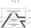
Wie in der
Die Fahrbahntrennlinien-Erfassungssektion M106 scannt die Pixel von der (m2+1)-ten Zeile bis zur m-ten Zeile in der Fahrbahntrennlinienerfassungs-Scannregion A101, jeweils eine Zeile auf einmal, von der mittleren Position des Bildes in der Richtung nach links ab. Das heißt, die linksseitigen Pixel von der (n/2)-ten Spalte bis zur ersten Spalte werden in dieser Reihenfolge gescannt. Zu diesem Zeitpunkt erfasst die Fahrbahntrennlinien-Erfassungssektion M106 die Pixel, in welchen die Binärzahl Schwarz „1“ repräsentiert unter den Pixeln von der (m2+1)-ten Zeile bis zur m-ten Zeile als einen in Frage kommenden Fahrbahntrennlinienmerkmalspunkt. Unter Verwendung der festliegenden Schablone für eine Fahrbahntrennlinienerfassung wird für den in Frage kommenden Fahrbahntrennlinienmerkmalspunkt ein Mustervergleich durchgeführt. Wenn bei dem Mustervergleich der in Frage kommende Fahrbahntrennlinienmerkmalspunkt „1“ mit dem vorab gesetzten Fahrbahntrennlinien-Merkmalspunktmuster, das durch die festliegende Schablone für eine Fahrbahntrennlinienerfassung repräsentiert ist, übereinstimmt, entscheidet die Fahrbahntrennlinien-Erfassungssektion M106, dass der in Frage kommende Fahrbahntrennlinienmerkmalspunkt ein linksseitiger Fahrbahntrennlinienmerkmalspunkt ist (Schritt S106).The lane-dividing line detection section M106 scans the pixels from the (m2+1)-th line to the m-th line in the lane-dividing line detection scanning region A101 one line at a time from the center position of the image in the left direction. That is, the left side pixels from the (n/2)th column to the first column are scanned in this order. At this time, the lane-dividing-line detecting section M106 detects the pixels in which the binary number black represents “1” among the pixels from the (m2+1)-th line to the m-th line as a lane-dividing line feature point in question. Using the fixed template for lane dividing line detection, a pattern match is performed for the lane dividing line feature point in question. In the pattern comparison, when the lane-dividing line feature point "1" in question matches the preset lane-dividing line feature point pattern represented by the fixed template for lane-dividing line detection, the lane-dividing line detection section M106 decides that the lane-dividing line feature point in question is a left-side lane-dividing line feature point (Step S106).
Die Fahrbahntrennlinien-Erfassungssektion M106 scannt die Pixel von der (m2+1)-ten Zeile bis zur m-ten Zeile in der Fahrbahntrennlinienerfassungs-Scannregion A101 jeweils eine Zeile auf einmal, von der mittleren Position des Bildes in der Richtung nach rechts. Das heißt, es werden die rechtsseitigen Pixel von der (n/2)-ten Spalte bis zur n-ten Spalte in dieser Reihenfolge gescannt. Hierbei erfasst die Fahrbahntrennlinien-Erfassungssektion M106 die Pixel, in welchen die Binärzahl Schwarz „1“ repräsentiert, als einen in Frage kommenden Fahrbahntrennlinienmerkmalspunkt unter den Pixeln von der (m2+1)-ten Zeile bis zur m-ten Zeile. Unter Verwendung der festliegenden Schablone für eine Fahrbahntrennlinienerfassung wird für den in Frage kommenden Fahrbahntrennlinienmerkmalspunkt ein Mustervergleich durchgeführt. Wenn bei dem Mustervergleich der in Frage kommende Fahrbahntrennlinienmerkmalspunkt „1“ mit dem vorab gesetzten Fahrbahntrennlinien-Merkmalspunktmuster, das durch die festliegende Schablone für eine Fahrbahntrennlinienerfassung repräsentiert ist, übereinstimmt, entscheidet die Fahrbahntrennlinien-Erfassungssektion M106, dass der in Frage kommende Fahrbahntrennlinienmerkmalspunkt der rechtsseitige Fahrbahntrennlinienmerkmalspunkt ist (Schritt S107).The lane-dividing line detection section M106 scans the pixels from the (m2+1)-th line to the m-th line in the lane-dividing line detection scanning region A101 one line at a time, from the middle position of the image in the right direction. That is, the right-side pixels are scanned from the (n/2)th column to the nth column in this order. Here, the lane-dividing line detection section M106 detects the pixels in which the binary number black represents “1” as a lane-dividing line feature point candidate among the pixels from the (m2+1)-th line to the m-th line. Using the fixed template for lane dividing line detection, a pattern match is performed for the lane dividing line feature point in question. In the pattern comparison, when the lane-dividing line feature point "1" in question matches the preset lane-dividing line feature point pattern represented by the fixed template for lane-dividing line detection, the lane-dividing line detection section M106 decides that the lane-dividing line feature point in question is the right-hand lane-dividing line feature point (Step S107).
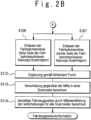
Die Fahrbahntrennlinien-Erfassungssektion M106 scannt die Pixel in der Fahrbahntrennlinienerfassungs-Scannregion A101 jeweils eine Zeile auf einmal, und führt einen Vervollständigungsvorgang durch, um den Teil zu vervollständigen, in welchem der Fahrbahntrennlinienmerkmalspunkt nicht erfasst worden ist (Schritt S 112). Diese Vervollständigung wird wie folgt durchgeführt. Wenn die Fahrbahntrennlinien-Erfassungssektion M106 die Pixel in der Fahrbahntrennlinienerfassungs-Scannregion A101 jeweils eine Zeile auf einmal, scannt, wird angenommen, dass ein Fahrbahntrennlinienmerkmalspunkt auf einer Seite, der linken Seite oder der rechten Seite der Fahrbahntrennlinienerfassungs-Scannregion A101 erfasst wird und auf der anderen Seite nicht erfasst wird. In diesem Fall wird auf der rechten Seite oder linken Seite, an der kein Fahrbahntrennlinienmerkmalspunkt erfasst worden ist, das zentrale Pixel der rechten oder linken Regionhälfte auf der seitlichen Scannlinie als ein vervollständigter Fahrbahntrennlinienmerkmalspunkt vervollständigt, um einen fehlenden Punkt einer Fahrbahntrennlinie zu vervollständigen.The lane-dividing line detection section M106 scans the pixels in the lane-dividing line detection scanning region A101 one line at a time, and performs a completion process to complete the part where the lane-dividing line feature point has not been detected (step S112). This completion is performed as follows. When the lane-dividing line detection section M106 scans the pixels in the lane-dividing line detection scanning region A101 one line at a time, it is assumed that a lane-dividing line feature point is detected on one side, the left side or the right side of the lane-dividing line detection scanning region A101 and on the other page is not detected. In this case, on the right side or left side where no lane-dividing line feature point has been detected, the central pixel of the right or left half region on the lateral scanning line is completed as a completed lane-dividing line feature point to to complete a missing point of a lane division line.
Wenn beispielsweise die Fahrbahntrennlinien-Erfassungssektion M106 die Pixel in der Fahrbahntrennlinienerfassungs-Scannregion A101 jeweils eine Zeile auf einmal scannt, wird angenommen, dass der rechtsseitige Fahrbahntrennlinienmerkmalspunkt erfasst wird, und es wird angenommen, dass der linksseitige Fahrbahntrennlinienmerkmalspunkt nicht erfasst wird. In diesem Fall wird bei den linken Pixeln, aus welchen der linksseitige Fahrbahntrennlinienmerkmalspunkt nicht erfasst werden kann, das Pixel auf der (n/2)-ten Spalte, welches das zentrale Pixel ist, als der vervollständigte Fahrbahntrennlinienmerkmalspunkt vervollständigt. Ähnlich wird, wenn die Fahrbahntrennlinien-Erfassungssektion M106 die Pixel der Fahrbahntrennlinienerfassungs-Scannregion A101 jeweils eine Zeile auf einmal scannt, angenommen, dass der linksseitige Fahrbahntrennlinienmerkmalspunkt erfasst wird, und es wird angenommen, dass der rechtsseitige Fahrbahntrennlinienmerkmalspunkt nicht erfasst wird. In diesem Fall wird aus den rechten Pixeln, aus welchen der rechtsseitige Fahrbahntrennlinienmerkmalspunkt nicht erfasst werden kann, das Pixel auf der (n/2)-ten Spalte, das das zentrale Pixel ist, als der vervollständigte Fahrbahntrennlinienmerkmalspunkt vervollständigt. Durch diesen Vervollständigungsvorgang werden die auf der rechten oder linken Fahrbahntrennlinie positionierten Punkte, die jedoch auf dem Bild fehlen, vervollständigt.For example, when the lane-dividing line detection section M106 scans the pixels in the lane-dividing line detection scanning region A101 one line at a time, the right-side lane-dividing line feature point is assumed to be detected and the left-side lane-dividing line feature point is assumed not to be detected. In this case, in the left pixels from which the left-hand lane-dividing line feature point cannot be detected, the pixel on the (n/2)-th column, which is the central pixel, is completed as the completed lane-dividing line feature point. Similarly, when the lane-dividing line detection section M106 scans the pixels of the lane-dividing line detection scanning region A101 one line at a time, it is assumed that the left-side lane-dividing line feature point is detected and it is assumed that the right-side lane-dividing line feature point is not detected. In this case, among the right pixels from which the right-side lane-dividing-line feature point cannot be detected, the pixel on the (n/2)-th column, which is the center pixel, is completed as the completed lane-dividing-line feature point. This completion process completes the points positioned on the right or left lane division line but missing from the image.
Die Fahrbahntrennlinien-Erfassungssektion M106 sendet die Fahrbahntrennlinienmerkmalspunkte (den linksseitigen Fahrbahntrennlinienmerkmalspunkt und den rechtsseitigen Fahrbahntrennlinienmerkmalspunkt), (den linksseitigen Fahrbahntrennlinienmerkmalspunkt und den vervollständigen rechtsseitigen Fahrbahntrennlinienmerkmalspunkt) und (den rechtsseitigen Fahrbahntrennlinienmerkmalspunkt und den vervollständigten linksseitigen Fahrbahntrennlinienmerkmalspunkt) an die Fahrzeugpositions-Schätzsektion M109, wenn die Pixel in der Fahrbahntrennlinienerfassungs-Scannregion A101 jeweils eine Zeile auf einmal gescannt worden sind.The road partnership recovering section M106 sends the lane tunneling line feature (the left-sided roadway point and the right-sided lane terminating point), (the left-sided lane terms of the lane tennis point and the on the right side of the road) and (the right-sided road terminals and accepts the constantly left-handed lane tennis point) to the vehicle position estimation section M109 if the pixels in of the lane division line detection scanning region A101 have been scanned one line at a time.
Die Fahrzeugpositions-Schätzsektion M109 berechnet die Fahrzeugposition, von der angenommen wird, dass sie die Position des Fahrzeugs auf der Fahrbahn anzeigt, als einen Merkmalspunkt auf der Fahrbahn in Übereinstimmung mit den Fahrbahntrennlinienmerkmalspunkten (dem linksseitigen Fahrbahntrennlinienmerkmalspunkt und dem rechtsseitigen Fahrbahntrennlinienmerkmalspunkt), (dem linksseitigen Fahrbahntrennlinienmerkmalspunkt und dem vervollständigten rechtsseitigen Fahrbahntrennlinienmerkmalspunkt) und (dem rechtsseitigen Fahrbahntrennlinienmerkmalspunkt und dem vervollständigten linksseitigen Fahrbahntrennlinienmerkmalspunkt), die durch die Fahrbahntrennlinien-Erfassungssektion M106 jeweils eine Zeile auf einmal erfasst worden sind.The vehicle position estimating section M109 calculates the vehicle position assumed to indicate the position of the vehicle on the lane as a feature point on the lane in accordance with the lane dividing line feature points (the left side lane dividing line feature point and the right side lane dividing line feature point), (the left side lane dividing line feature point and the completed right-side lane-dividing line feature point) and (the right-side lane-dividing line feature point and the completed left-side lane-dividing line feature point) detected by the lane-dividing line detecting section M106 one line at a time.
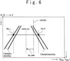
Wie im Einzelnen in der
Wenn die derzeitige Fahrzeugposition auf einer Scannlinie als die Position center_pos angenommen wird, berechnet die Fahrzeugpositions-Schätzsektion M109 die derzeitige Fahrzeugposition center_pos durch die folgende Gleichung:
Als Nächstes repräsentieren der Koordinatenwert (0, Xmax/2) bzw. (Ymax, Xmax/2) die Pixel der (m2+1)-ten Zeile (n/2)-ten Spalte und der m-ten Zeile, (n/2)-ten Spalte, die als die zentrale Position des Bildes auf einer Scannlinie definiert sind. Dann wird die zentrale Position als CENTER und das Maß der Abweichung der Fahrzeugposition center_pos zur zentralen Position CENTER als line_delta definiert, die Fahrzeugpositions-Schätzsektion berechnet das Maß der Abweichung line_delta zur zentralen Position CENTER des Bildes auf einer Scannlinie durch die folgende Gleichung:
Diese Berechnung wird für jede Scannlinie zwischen den (m2+1)-ten und m-ten Zeilen in der Fahrbahntrennlinienerfassungs-Scannregion A101 durchgeführt (Schritt S113).This calculation is performed for each scan line between the (m2+1)-th and m-th rows in the lane division line detection scan region A101 (step S113).
Als Nächstes berechnet die Fahrzeugpositions-Schätzsektion M109 den Mittelwert der Abweichungsmaße line_delta von der mittleren Position CENTER, die für alle Scannzeilen zwischen der (m2+1)-ten und m-ten Zeile bestimmt worden sind, und bestimmt die laufende Fahrzeugposition in Übereinstimmung mit dem Mittelwert (Schritt S114).Next, the vehicle position estimating section M109 calculates the average of the deviation amounts line_delta from the center position CENTER obtained for all scan lines between the (m2+1)-th and m-th lines have been determined, and determines the current vehicle position in accordance with the mean value (step S114).
Im Einzelnen berechnet die Fahrzeugpositions-Schätzsektion M109 durch Definieren der Summe der Abweichungsgrößen line _delta gegenüber der mittleren Position CENTER bezogen auf alle Zeilen zwischen der (m2+1)-ten und m-ten Zeile als Σline _delta und den Mittelwert der Abweichungsgrößen line _delta als frame_delta, einen Mittelwert frame_delta durch die folgende Gleichung:
Ferner berechnet die Fahrzeugpositions-Schätzsektion M109 die derzeitige Fahrzeugfahrposition Current CENTER, die die laufende Position des Fahrzeugs angibt, durch die folgende Gleichung:
Wenn hierbei Current_ CENTER > 0 ist, zeigt dies an, dass das Fahrzeug auf der rechten Seite der mittleren Position des Bildes ist, und wenn Current_ CENTER < 0 ist, zeigt dies an, dass das Fahrzeug auf der rechten Seite der zentralen Position des Bildes ist.Here, when Current_CENTER > 0, it indicates that the vehicle is on the right side of the center position of the image, and when Current_CENTER < 0, it indicates that the vehicle is on the right side of the center position of the image is.
In dem Schritt S114 gibt die Fahrzeugpositions-Schätzsektion M109 die berechnete derzeitige Fahrzeugposition als die Fahrpositionsinformation an das automatische Fahrsystem M200 aus. Oder es können die derzeitige Fahrzeugposition und die Fahrbahntrennlinienmerkmalspunkte (der rechtsseitige Fahrbahntrennlinienmerkmalspunkt und der linksseitige Fahrbahntrennlinienmerkmalspunkt) als Fahrpositionsinformation an das automatische Fahrsystem M200 ausgegeben werden.In step S114, the vehicle position estimating section M109 outputs the calculated current vehicle position as the running position information to the automatic running system M200. Or, the current vehicle position and the lane-dividing-line feature points (the right-side lane-dividing line feature point and the left-side lane-dividing line feature point) may be output as driving position information to the automatic driving system M200.
Die Abzweigungserfassungssektion M107 scannt die Pixel von der (m1+1)-ten Zeile bis zur m2-ten Zeile in der Abzweigungserfassungs-Scannregion A102 jeweils eine Zeile auf einmal von der mittleren Position des Bildes in der Richtung nach links. Das heißt, die Pixel von der (n/2)-ten Spalte bis zur ersten Spalte werden in der genannten Reihenfolge gescannt. Hierbei erfasst die Abzweigungserfassungssektion M107 das Pixel, dessen Binärzahl Schwarz „1“ repräsentiert, unter den Pixeln von der (m1+1)-ten Zeile bis zur m2-ten-Zeile als einen in Frage kommenden Abzweigungsmerkmalspunkt. Die Abzweigungserfassungssektion M107 führt einen Mustervergleich des erfassten in Frage kommenden Abzweigungsmerkmalspunkts unter Verwendung der festliegenden Schablone für die Abzweigungserfassung durch. Wenn der in Frage kommende Abzweigungsmerkmalspunkt „1“ beim Mustervergleich mit dem vorab gesetzten Abzweigungs-Merkmalspunktmuster, das durch die festliegende Schablone für die Abzweigungserfassung repräsentiert ist, übereinstimmt, entscheidet die Abzweigungserfassungssektion M107, dass der in Frage kommende Abzweigungsmerkmalspunkt ein linker Abzweigungsmerkmalspunkt ist (Schritt S108).The intersection detection section M107 scans the pixels from the (m1+1)-th line to the m2-th line in the intersection detection scanning region A102 one line at a time from the center position of the image in the left direction. That is, the pixels from the (n/2)th column to the first column are scanned in the named order. Here, the intersection detection section M107 detects the pixel whose binary number represents black "1" among the pixels from the (m1+1)-th line to the m2-th line as a candidate intersection feature point. The intersection detection section M107 performs pattern matching of the detected intersection candidate feature point using the fixed template for intersection detection. When the candidate intersection feature point "1" matches the preset intersection feature point pattern represented by the fixed template for intersection detection in the pattern comparison, the intersection detection section M107 decides that the intersection candidate point is a left intersection feature point (step S108 ).
Die Abzweigungserfassungssektion M107 scannt die Pixel von der (m1+1)-ten Zeile bis zur m2-ten Zeile als der Abzweigungserfassungs-Scannregion A102, jeweils eine Zeile auf einmal, von der mittleren Position des Bildes in der Richtung nach rechts. Das heißt, die Pixel von der (n/2)-ten Spalte bis zur n-ten Spalte werden in der genannten Reihenfolge gescannt. Hierbei erfasst die Abzweigungserfassungssektion M107 das Pixel, dessen Binärzahl Schwarz „1“ repräsentiert, unter den Pixeln von der (m1+1)-ten Zeile bis zur m2-ten Zeile als einen in Frage kommenden Abzweigungsmerkmalspunkt. Die Abzweigungserfassungssektion M107 führt einen Mustervergleich des erfassten in Frage kommenden Abzweigungsmerkmalspunkts unter Verwendung der festliegenden Schablone für die Abzweigungserfassung durch. Wenn bei dem Mustervergleich der in Frage kommende Abzweigungsmerkmalspunkt „1“ mit dem vorab gesetzten Abzweigungs-Merkmalspunktmuster, das durch die festliegende Schablone für die Abzweigungserfassung repräsentiert ist, übereinstimmt, entscheidet die Abzweigungserfassungssektion M107, dass der in Frage kommende Abzweigungsmerkmalspunkt ein rechter Abzweigungsmerkmalspunkt ist (Schritt S109).The intersection detection section M107 scans the pixels from the (m1+1)-th line to the m2-th line as the intersection detection scanning region A102, one line at a time, from the center position of the image in the right direction. That is, the pixels from the (n/2)th column to the nth column are scanned in the named order. Here, the intersection detection section M107 detects the pixel whose binary number represents black "1" among the pixels from the (m1+1)-th line to the m2-th line as a candidate intersection feature point. The intersection detection section M107 performs pattern matching of the detected intersection candidate feature point using the fixed template for intersection detection. In the pattern matching, when the candidate intersection feature point "1" matches the preset intersection feature point pattern represented by the fixed template for intersection detection, the intersection detection section M107 decides that the candidate intersection feature point is a right intersection feature point (step S109).
Die Abzweigungserfassungssektion M107 erzeugt eine Abzweigungsinformation, die anzeigt, ob der erzielte Abzweigungsmerkmalspunkt (der rechte Abzweigungsmerkmalspunkt oder der linke Abzweigungsmerkmalspunkt) auf der rechten Seite der mittleren Position des Bildes existiert oder auf der linken Seite existiert oder an beiden Seiten der rechten und linken Seite existiert oder auf den beiden Seiten rechts und links nicht existiert, und gibt dann die Abzweigungsinformation an das automatische Fahrsystem M200 aus (Schritt S 115).The intersection detecting section M107 generates intersection information indicating whether the obtained intersection feature point (the right intersection feature point or the left intersection feature point) exists on the right side of the center position of the image, or exists on the left side, or exists on both sides of the right and left sides, or does not exist on both the right and left sides, and then outputs the intersection information to the automatic driving system M200 (step S115).
Die Sackgassen- und Hinderniserfassungssektion M108 scannt die Pixel von der ersten Zeile bis zur m1-ten Zeile in der Sackgassen- und Hinderniserfassungs-Scannregion A103 jeweils eine Zeile auf einmal, von der mittleren Position des Bildes in der Richtung nach links. Das heißt, die Pixel von der (n/2)-ten Spalte bis zur ersten Spalte werden in der genannten Reihenfolge gescannt. Hierbei erfasst die Sackgassen- und Hinderniserfassungssektion M108, dessen Binärzahl „1“ repräsentiert, als einen in Frage kommenden Sackgassen- und Hindernismerkmalspunkt, unter den Pixeln von der ersten Zeile bis zur m1-ten Zeile. Die Sackgassen- und Hinderniserfassungssektion M108 führt einen Mustervergleich des erfassten in Frage kommenden Sackgassen- und Hindernismerkmalspunkts unter Verwendung der festliegenden Schablone für die Sackgassen- und Hinderniserfassung durch. Wenn der Mustervergleich der in Frage kommende Sackgassen- und Hindernismerkmalspunkt „1“ mit dem vorab gesetzten Sackgassen- und Hindernis-Merkmalspunktmuster übereinstimmt, das durch die festliegende Schablone für die Sackgassen- und Hinderniserfassung repräsentiert ist, entscheidet die Sackgassen- und Hinderniserfassungssektion M108, dass der in Frage kommende Sackgassen- und Hindernismerkmalspunkt ein linker Sackgassen- und Hindernismerkmalspunkt ist (Schritt S 110).The dead end and obstacle detection section M108 scans the pixels from the first line to the m1-th row in the dead end and obstacle detection scanning region A103 one line at a time, from the center position of the image in the left direction. That is, the pixels from the (n/2)th column to the first column are scanned in the named order. Here, the dead end and obstacle detection section detects M108 whose binary number represents “1” as a candidate dead end and obstacle feature point, among the pixels from the first line to the m1-th line. The dead end and obstacle detection section M108 makes a pattern matching of the detected candidate sack alley and obstacle feature point using the fixed dead end and obstacle detection template. If the pattern matching of the candidate dead end and obstacle feature point "1" matches the preset dead end and obstacle feature point pattern represented by the fixed template for dead end and obstacle detection, the dead end and obstacle detection section M108 decides that the candidate dead end and obstacle feature point is a left dead end and obstacle feature point (step S110).
Die Sackgassen- und Hinderniserfassungssektion M108 scannt die Pixel von der ersten Zeile bis zur m1-ten Zeile als der Sackgassen- und Hinderniserfassungs-Scannregion A103, jeweils eine Zeile auf einmal von der zentralen Position des Bildes in der Richtung nach rechts. Das heißt, die Pixel von der (n/2)-ten Spalte bis zur n-ten Spalte werden in der genannten Reihenfolge gescannt. Hierbei erfasst die Sackgassen- und Hinderniserfassungssektion M108 das Pixel, dessen Binärzahl Schwarz „1“ repräsentiert, als einen in Frage kommenden Sackgassen- und Hindernismerkmalspunkt unter den Pixeln von der ersten Zeile bis zur m1-ten Zeile. Die Sackgassen- und Hinderniserfassungssektion M108 führt einen Mustervergleich des erfassten in Frage kommenden Sackgassen- und Hindernismerkmalspunkts unter Verwendung der festliegenden Schablone für die Sackgassen- und Hinderniserfassung durch. Wenn bei dem Mustervergleich der in Frage kommende Sackgassen- und Hindernismerkmalspunkt „1“ mit dem vorab gesetzten Sackgassen- und Hindernis-Merkmalspunktmuster, das durch die festliegende Schablone für die Sackgassen- und Hinderniserfassung repräsentiert ist, übereinstimmt, entscheidet die Sackgassen- und Hinderniserfassungssektion M108, dass der in Frage kommende Sackgassen- und Hindernismerkmalspunkt ein rechter Sackgassen- und Hindernismerkmalspunkt ist (Schritt S111).The dead end and obstacle detection section M108 scans the pixels from the first line to the m1-th line as the dead end and obstacle detection scanning region A103 one line at a time from the center position of the image in the right direction. That is, the pixels from the (n/2)th column to the nth column are scanned in the named order. Here, the dead end and obstacle detection section M108 detects the pixel whose binary number represents black "1" as a candidate dead end and obstacle feature point among the pixels from the first line to the m1-th line. The dead end and obstacle detection section M108 performs pattern matching of the detected dead end and obstacle feature point candidate using the fixed template for dead end and obstacle detection. In the pattern matching, if the candidate dead end and obstacle feature point "1" matches the preset dead end and obstacle feature point pattern represented by the fixed template for dead end and obstacle detection, the dead end and obstacle detection section M108 decides, that the dead end and obstacle feature point in question is a right dead end and obstacle feature point (step S111).
Die Sackgassen- und Hinderniserfassungssektion M108 erzeugt die Sackgassen- und Hindernisinformation und gibt diese an das automatische Fahrsystem M200 aus (Schritt S 116). Die Sackgassen- und Hindernisinformation, die anzeigt, ob der erzielte Sackgassen- und Hindernismerkmalspunkt (der rechte Sackgassen- und Hindernismerkmalspunkt und der linke Sackgassen- und Hindernismerkmalspunkt) an der rechten Seite zur mittleren Position des Bildes existiert oder auf der linken Seite existiert oder sowohl auf der rechten und linken Seite existiert oder weder auf der rechten noch auf der linken Seite existiert.The dead end and obstacle detection section M108 generates the dead end and obstacle information and outputs them to the automatic driving system M200 (step S116). The dead end and obstacle information indicating whether the obtained dead end and obstacle feature point (the right dead end and obstacle feature point and the left dead end and obstacle feature point) exists on the right side to the center position of the image, or exists on the left side, or both exists on the right and left side or exists neither on the right nor on the left side.
[Vergleich][Comparison]
Es werden hier ein eingebautes Bildverarbeitungsgerät M100 für Fahrzeuge gemäß einer Ausführungsform der vorliegenden Erfindung und ein Bezugsbeispiel eines eingebauten Bildverarbeitungsgeräts für Fahrzeuge (ein Fahrbahnmarkierungs-Erkennungsgerät und ein Fahrzeughindernis-Erfassungsgerät) verglichen.Here, an on-vehicle image processing device M100 according to an embodiment of the present invention and a reference example of an on-vehicle image processing device (a lane-marker recognition device and a vehicle obstacle detection device) are compared.
[Vergleich 1][Comparison 1]
In einem eingebauten Bildverarbeitungsgerät M100 für Fahrzeuge gemäß einer Ausführungsform der vorliegenden Erfindung sind die Scannregionen, die jeweils irgendeiner der Arten von Merkmalspunkten auf der Straße zugewiesen sind (eine Fahrbahntrennlinie, eine Abzweigung, eine Sackgasse und ein Hindernis), für das Erfassen der Bilddaten (die Merkmalspunkt-Erfassungsbilddaten) gesetzt. Somit kann verglichen mit einem Fall, bei dem ein ganzes Bild für alle Arten von Merkmalspunkten gescannt wird, der Umfang des Scannvorgangs reduziert werden.In an on-vehicle image processing apparatus M100 according to an embodiment of the present invention, the scanning regions each assigned to any of the types of feature points on the road (a lane divider, a junction, a dead end and an obstacle) for capturing the image data (the feature point detection image data). Thus, compared to a case where an entire image is scanned for all kinds of feature points, the amount of scanning can be reduced.
In einem eingebauten Bildverarbeitungsgerät für Fahrzeuge gemäß einem Bezugsbeispiel (insbesondere einem Fahrbahnmarkierungs-Erkennungsgerät) wird als Vorgang zum Erfassen von Mustern, wie beispielsweise einer Fahrbahnmarkierung, einer Abzweigung, einer Sackgasse und eines Hindernisses, die gesamte Region des Bildes gescannt, mit Durchführung des Mustervergleichs der abgetasteten Pixel und der festliegenden Schablonen, die jeweils den Mustern entsprechen. In diesem Fall wird die gesamte Region gescannt, was zu dem Problem führt, dass das Maß der Vorgänge beim Durchführen des Scannens entsprechend der Ganzbildgröße des Bildes groß wird.In an on-vehicle image processing apparatus according to a reference example (particularly, a lane marking recognition apparatus), as a process for detecting patterns such as a lane marking, a junction, a dead end, and an obstacle, the entire region of the image is scanned with performing the pattern matching of the scanned pixels and the fixed templates corresponding to the patterns, respectively. In this case, the entire region is scanned, resulting in a problem that the amount of operations when performing scanning becomes large according to the frame size of the image.
Andererseits ist in dem eingebauten Bildverarbeitungsgerät M100 für Fahrzeuge gemäß einer Ausführungsform der vorliegenden Erfindung die gesamte Fläche der Erfassungsbilddaten in die Fahrbahntrennlinienerfassungs-Scannregion A101, die Abzweigungserfassungs-Scannregion A102 und die Sackgassen- und Hinderniserfassungs-Scannregion A103 unterteilt. Dann werden die Pixel in der Fahrbahntrennlinienerfassungs-Scannregion A101, der Abzweigungserfassungs-Scannregion A102 und der Sackgassen- und Hinderniserfassungs-Scannregion A103 jeweils eine Zeile auf einmal von der Fahrbahntrennlinien-Erfassungssektion M106, der Abzweigungserfassungssektion M107 und der Sackgassen- und Hinderniserfassungssektion M108 gescannt. Auf diese Weise sind die Erfassungsbilddaten in dem eingebauten Bildverarbeitungsgerät M100 für Fahrzeuge gemäß dieser Ausführungsform in die Fahrbahntrennlinienerfassungs-Scannregion A101, die Abzweigungserfassungs-Scannregion A102 und die Sackgassen- und Hinderniserfassungs-Scannregion A103 unterteilt. Somit kann die Informationsmenge, die beim Scannen verarbeitet wird, reduziert werden.On the other hand, in the on-vehicle image processing apparatus M100 according to an embodiment of the present invention, the entire area of the detection image data is divided into the lane division detection scanning region A101, the intersection detection scanning region A102, and the dead end and obstacle detection scanning region A103. Then, the pixels in the lane-dividing line detection scanning region A101, the intersection detection scanning region A102, and the dead-end and obstacle detection scanning region A103 are scanned one line at a time by the lane-dividing line detection section M106, the intersection detection section M107, and the dead-end and obstacle detection section M108. In this way, in the on-vehicle image processing apparatus M100 according to this embodiment, the detection image data is in the lane division line detection scanning region A101, the intersection detection scanning region A102 and the dead end and obstacle detection scanning region A103. Thus, the amount of information processed in scanning can be reduced.
Auch der Abstand zwischen dem Fahrzeug und dem Punkt entsprechend den m Zeilen und n Spaltenpixeln der Erfassungsbilddaten wird von der ersten Zeile bis zur m-ten Zeile in der genannten Reihenfolge kürzer. Es wird auch 1 < m1 < m2 < m angenommen. In diesem Fall entsprechen die Sackgassen- und Hinderniserfassungs-Scannregion A103, die Abzweigungserfassungs-Scannregion A102 und die Fahrbahntrennlinienerfassungs-Scannregion A101 den Pixeln von der ersten Zeile bis zur m1-ten Zeile, den Pixeln von der (m1+1)-ten Zeile bis zur m2-ten Zeile bzw. den Pixeln von der (m2+1)-ten Zeile bis zur m-ten Zeile unter den m Zeilen und n Spaltenpixeln der Erfassungsbilddaten. Folglich gibt es die folgenden Vorzüge.Also, the distance between the vehicle and the point corresponding to the m-row and n-column pixels of the detection image data becomes shorter from the first row to the m-th row in the named order. It is also assumed that 1<m1<m2<m. In this case, the dead end and obstacle detection scanning region A103, the intersection detection scanning region A102, and the lane division line detection scanning region A101 correspond to the pixels from the first line to the m1-th line, to the pixels from the (m1+1)-th line to to the m2-th row or the pixels from the (m2+1)-th row to the m-th row among the m row and n column pixels of the capture image data. Consequently, there are the following merits.
Zunächst wird das Merkmal des Bildes (die Perspektive des Bildes, nämlich der Vordergrund erscheint groß, und der Hintergrund erscheint klein) dafür verwendet, die Scannregion auf der Grundlage des zu erfassenden Zielobjekts zu spezifizieren. Somit kann in der Scannregion der Einfluss von Rauschen unterdrückt werden, und das fehlerhafte Erfassen von Merkmalspunkten kann verringert werden.First, the feature of the image (the perspective of the image, namely the foreground appears large and the background appears small) is used to specify the scan region based on the target to be detected. Thus, in the scanning region, the influence of noise can be suppressed, and erroneous detection of feature points can be reduced.
Zweitens ist die Fahrbahntrennlinienerfassungs-Scannregion A101 im Vordergrund gesetzt (die untere Region des Bildes). Somit kann, selbst wenn das Fahrzeug stark von der Mitte einer Fahrbahn abweicht oder in einer Kurve fährt, wenigstens ein Teil einer Fahrbahntrennlinie abgebildet werden. Daher ist es einfach, den Vorgang zum Berechnen der Fahrzeugposition durchzuführen.Second, the lane-dividing line detection scanning region A101 is set in the foreground (the lower region of the image). Thus, even when the vehicle largely deviates from the center of a lane or is turning, at least a part of a lane division line can be imaged. Therefore, it is easy to perform the vehicle position calculation process.
Drittens wird die vom Fahrzeug entfernte Region gescannt, um die Sackgasse und ein Hindernis zu erfassen, sodass die Anwesenheit oder Abwesenheit einer Sackgasse oder eines Hindernisses früher als die Anwesenheit oder Abwesenheit einer Abzweigung erkannt werden kann. Wenn somit das automatische Fahrsystem M200 die Bewegung des Fahrzeugs in Antwort auf die erfassten Merkmalspunkte steuert, wird es einfach, die Entscheidung für das Steuern der Fahrzeugbewegung in Antwort auf die Anwesenheit oder Abwesenheit einer Sackgasse oder eines Hindernisses auszuführen.Third, the region far from the vehicle is scanned to detect the dead end and an obstacle, so that the presence or absence of a dead end or obstacle can be recognized earlier than the presence or absence of a junction. Thus, when the automatic driving system M200 controls the movement of the vehicle in response to the detected feature points, it becomes easy to make the decision for controlling the vehicle movement in response to the presence or absence of a dead end or an obstacle.
Auf diese Weise kann in dem eingebauten Bildverarbeitungsgerät M100 für Fahrzeuge der vorliegenden Ausführungsform wegen der Anordnung der zugewiesenen Scannregionen der Einfluss von Rauschen unterdrückt werden, und das fehlerhafte Erfassen von Merkmalspunkten kann reduziert werden. Somit kann die bei dem Scannen verarbeitete Informationsmenge reduziert werden. Wenn beispielsweise die Scannregion als 1/3 des gesamten Bildes definiert ist, ist die zu verarbeitende Informationsmenge ebenfalls 1/3.In this way, in the on-vehicle image processing apparatus M100 of the present embodiment, because of the arrangement of the assigned scanning regions, the influence of noise can be suppressed, and erroneous detection of feature points can be reduced. Thus, the amount of information processed in the scanning can be reduced. For example, if the scan region is defined as 1/3 of the entire image, the amount of information to be processed is also 1/3.
[Vergleich 2][Comparison 2]
In einem eingebauten Bildverarbeitungsgerät M100 für Fahrzeuge gemäß dieser Ausführungsform wird für ein linksseitiges Pixel oder ein rechtsseitiges Pixel, das an einer Fahrbahntrennlinie positioniert, jedoch nicht erfasst ist, das Pixel, das in der Mitte der linken Halbregion oder rechten Halbregion positioniert ist, als der ergänzte Fahrbahntrennlinienmerkmalspunkt ergänzt. Somit kann die derzeit geschätzte Fahrzeugposition verglichen mit dem Fall, bei dem keine Ergänzung ausgeführt wird, an die wahre Fahrzeugposition angenähert werden.In an on-vehicle image processing apparatus M100 according to this embodiment, for a left-hand pixel or a right-hand pixel positioned at a lane division line but not detected, the pixel positioned at the center of the left half region or right half region is used as the supplemented one Lane dividing line feature point added. Thus, the currently estimated vehicle position can be approximated to the true vehicle position compared to the case where supplementation is not performed.
In einem Referenzbeispiel eines eingebauten Bildverarbeitungsgeräts für Fahrzeuge, das keine Ergänzungsfunktion hat, werden, wenn ein Fahrzeug fährt, eine Fahrbahntrennlinie, die sich von unten links nach oben rechts, auf der linken Seite des Fahrzeugs gelegen, und eine andere, die sich von unten rechts nach oben links auf der rechten Seite des Fahrzeugs gelegen erstreckt, abgebildet. Die derzeitige Fahrzeugposition wird auf der Grundlage des Maßes der Anordnung zur Bildmitte in seitlicher Richtung erkannt, das in Übereinstimmung mit den Positionen der linken und rechten Fahrbahntrennlinien erzielt worden ist, die durch einen Mustervergleich eines Paars der Kante der rechten Fahrbahntrennlinie und der linken Fahrbahntrennlinie mit einer festliegenden Schablone berechnet worden sind. In dem Fall, bei dem die Fahrzeugposition stark von der Fahrbahn abweicht oder wenn das Fahrzeug in einer Kurve fährt, wird jedoch nur eine der rechten und linken Fahrbahntrennlinien abgebildet. Als Ergebnis wird eine Kantenpaar der linken und rechten Fahrbahntrennlinien bei dem Mustervergleich unter Verwendung der festliegenden Schablone nicht erfasst, sodass die Fahrzeugposition nicht berechnet werden kann.In a reference example of an on-vehicle image processing apparatus that has no supplemental function, when a vehicle is running, a lane dividing line extending from the lower left to the upper right is located on the left side of the vehicle and another one extending from the lower right extending to the upper left located on the right side of the vehicle. The current vehicle position is recognized based on the degree of arrangement to the image center in the lateral direction obtained in accordance with the positions of the left and right lane dividing lines obtained by pattern matching a pair of the edge of the right lane dividing line and the left lane dividing line with a fixed template have been calculated. However, in the case where the vehicle position deviates greatly from the lane or when the vehicle is running on a curve, only one of the right and left lane division lines is imaged. As a result, a pair of edges of the left and right lane dividing lines is not detected in the pattern matching using the fixed template, so that the vehicle position cannot be calculated.
Bei dem Bezugsbeispiel eines eingebauten Bildverarbeitungsgeräts für Fahrzeuge ohne Ergänzungsfunktion (insbesondere einem Fahrbahnmarkierungs-Erkennungsgerät) wird eine vorläufige Fahrbahntrennlinienposition auf der Grundlage der Position des Kantenpaars, zusammengesetzt aus der Oberkante und der Unterkante, definiert. Sofern jedoch nicht eine Extrapolierschaltung zum Erfassen eines Kantenpaars durch Scannen in der weiteren rechten und linken Richtung des Bildfeldes installiert ist, kann die Position der Fahrbahntrennlinien nicht erzielt werden. Bei einem automatischen Fahren macht dies den Betrieb unmöglich. Andererseits führt die Installation einer Ergänzungsschaltung zu dem Problem, dass die Schaltungsgröße vergrößert wird.In the reference example of an on-vehicle image processing device without a supplementary function (specifically, a lane-marking recognition device), a provisional lane-dividing-line position is defined based on the position of the pair of edges composed of the upper edge and the lower edge. However, unless an extrapolating circuit for detecting a pair of edges by scanning in the farther right and left direction of the field of view is installed, the position of the lane dividing lines cannot be obtained. In an automatic driving, this makes the operation impossible. On the other hand, the installation of a supplementary circuit leads to the problem that the circuit scale is increased.
Andererseits wird bei einem eingebauten Bildverarbeitungsgerät M100 für Fahrzeuge einer Ausführungsform der vorliegenden Erfindung ein Ergänzungsvorgang wie im Folgenden angegeben ausgeführt. Beim Scannen der Pixel auf der Fahrbahntrennlinienerfassungs-Scannregion A101, die jeweils eine Zeile auf einmal gescannt werden, wird angenommen, dass nur einer der linksseitigen und rechtsseitigen Fahrbahntrennlinienmerkmalspunkte erfasst wird und der andere nicht erfasst wird. Im Folgenden wird die linke oder rechte Regionhälfte, in der der andere Fahrbahntrennlinienmerkmalspunkt, der nicht erfasst ist, positioniert ist, als die Merkmalspunkt-Fehlregionhälfte bezeichnet. Die Merkmalspunkt-Fehlregionhälfte ist entweder die linke Regionhälfte, bestehend aus den Pixeln von der (n/2)-ten Spalte bis zur ersten Spalte oder die rechte Regionhälfte und die rechte Regionhälfte bestehend aus den Pixeln von der (n/2)-ten Spalte bis zur n-ten Spalte. In diesem Fall ist die mittlere Position in seitlicher Richtung in der Merkmalspunkt-Fehlregionhälfte als der ergänzte Fahrbahntrennlinienmerkmalspunkt der Regionhälfte definiert.On the other hand, in an on-vehicle image processing apparatus M100 of an embodiment of the present invention, a supplementing process is performed as follows. When scanning the pixels on the lane-dividing-line detection scanning region A101 one line at a time, it is assumed that only one of the left-hand and right-side lane-dividing line feature points is detected and the other is not detected. Hereinafter, the left or right half region in which the other lane division line feature point that is not detected is positioned is referred to as the feature point missing half region. The feature point missing half region is either the left half region composed of the pixels from the (n/2)th column to the first column or the right half region and the right half region composed of the pixels from the (n/2)th column up to the nth column. In this case, the middle position in the lateral direction in the feature point missing region half is defined as the supplemented lane division line feature point of the region half.
Dann wird die Position des Fahrzeugs auf der Straße in Übereinstimmung mit dem einen Fahrbahntrennlinienmerkmalspunkt in einer Regionhälfte und dem ergänzten Fahrbahntrennlinienmerkmalspunkt in der anderen Regionhälfte geschätzt. Auf diese Weise wird in dem eingebauten Bildverarbeitungsgerät M100 für Fahrzeuge dieser Ausführungsform in der Merkmalspunkt-Fehlregionhälfte der ergänzte Fahrbahntrennlinienmerkmalspunkt in der Merkmalspunkt-Fehlregionhälfte ergänzt. Als Ergebnis kann die Abweichung der geschätzten Fahrzeugposition von der wirklichen Fahrzeugposition reduziert werden. Daraus folgend gibt es die folgenden Vorteile.Then, the position of the vehicle on the road is estimated in accordance with the one lane-dividing line feature point in one half region and the added lane-dividing line feature point in the other half region. In this way, in the on-vehicle image processing apparatus M100 of this embodiment, in the feature point missing region half, the supplemented lane division line feature point is supplemented in the feature point missing region half. As a result, the deviation of the estimated vehicle position from the real vehicle position can be reduced. As a result, there are the following advantages.
Erstens wird, wie in der
Zweitens kann, wie in der
Beispielsweise ist in der
Auf diese Weise hat das eingebaute Bildverarbeitungsgerät M100 für Fahrzeuge dieser Ausführungsform einen breiten zulässigen Bereich für Rauschen, die Abweichung von der Fahrzeugposition und die Abweichung von der installierten Position der Kamera. Somit kann die Fahrzeugposition unter Verwendung einer Kantenerfassung auf der Grundlage einer festliegenden Schablone berechnet werden, ohne dass eine Extraschaltung oder ein Extravorgang zugefügt wird.In this way, the on-vehicle image processing apparatus M100 of this embodiment has a wide allowable range for noise, the deviation from the vehicle position, and the deviation from the installed position of the camera. Thus, the vehicle position can be calculated using edge detection based on a fixed template without adding an extra circuit or operation.
[Vergleich 3][Comparison 3]
In einem eingebauten Bildverarbeitungsgerät M100 für Fahrzeuge einer Ausführungsform der vorliegenden Erfindung kann die Anzahl der Schaltungen zum Erzielen eines Filterungsvorgangs für die Kantenerfassung reduziert werden. Somit kann die Schaltungsgröße reduziert werden.In an on-vehicle image processing apparatus M100 of an embodiment of the present invention, the number of circuits for achieving a filtering operation for edge detection can be reduced. Thus, the circuit scale can be reduced.
In einem Referenzbeispiel eines eingebauten Bildverarbeitungsgeräts für Fahrzeuge (insbesondere eines Geräts zum Erfassen eines Hindernisses auf einer Fahrbahn) werden zwei Arten von eindimensionalen Filterungsvorgängen durchgeführt, nämlich der horizontale (seitliche) und der vertikale (longitudinale) Kantenerfassungs-Filterungsvorgang. Somit sind bei dieser Referenztechnik die Schaltung zum Erzielen von zwei Arten von eindimensionalen Filterungsvorgängen erforderlich, sodass das Problem besteht, dass die Schaltungsgröße vergrößert ist.In a reference example of an on-vehicle image processing apparatus (specifically, an apparatus for detecting an obstacle on a road), two types of one-dimensional filtering processes, namely, horizontal (lateral) and vertical (longitudinal) edge detection filtering processes are performed. Thus, in this reference technique, the circuitry for achieving two kinds of one-dimensional filtering operations are required, so there is a problem that the circuit scale is increased.
Bei dem eingebauten Bildverarbeitungsgerät M100 für Fahrzeuge gemäß einer Ausführungsform der vorliegenden Erfindung kann andererseits der Filterungsvorgang unter Verwendung von nur einem zweidimensionalen Filterungsvorgang erzielt werden. Das heißt, er kann erzielt werden, indem nur eine Schaltung zum Erzielen eines zweidimensionalen Filterungsvorgangs zugefügt wird. Somit kann die Schaltungsgröße verglichen mit dem Referenzbeispiel verringert werden.On the other hand, in the on-vehicle image processing apparatus M100 according to an embodiment of the present invention, the filtering process can be performed using only one two-dimensional filtering process can be achieved. That is, it can be achieved only by adding a circuit for achieving a two-dimensional filtering process. Thus, the circuit scale can be reduced compared to the reference example.
In einer Ausführungsform der vorliegenden Erfindung kann der zweidimensionale Filterungsvorgang auch auf der Grundlage allein der Intensitäten der fokussierten Pixel und der umgebenden 8 Pixel durchgeführt werden. Um daher den zweidimensionalen Filterungsvorgang zu erzielen, ist es ausreichend, nur 3 Zeilen Puffer vorzubereiten, was die halbe Größe des Referenzbeispiels bedeutet. Wenn beispielsweise die Anzahl der Zeilenpuffer, die bei dem Referenzbeispiel des eingebauten Bildverarbeitungsgeräts für Fahrzeuge erforderlich ist, 6 ist, ist die Anzahl der bei dem eingebauten Bildverarbeitungsgerät M100 für Fahrzeuge einer Ausführungsform der vorliegenden Erfindung eingebauten Zeilenpuffer gleich 3. Hierbei ist in einem Zeilenpuffer die Anzahl der notwendigen Flip-Flops entsprechend der Bildgröße (seitlichen Breite) in 1 Ganzbild erhöht. Somit führt dies im Fall einer Bildgröße von 1000* 1000 [Pixel] pro 1 Ganzbild zu einer Verringerung von 3000 Flip-Flops.In an embodiment of the present invention, the two-dimensional filtering process can also be performed based solely on the intensities of the focused pixels and the surrounding 8 pixels. Therefore, in order to achieve the two-dimensional filtering process, it is sufficient to prepare only 3 lines of buffers, which is half the size of the reference example. For example, if the number of line buffers required in the reference example of the on-vehicle image processing device is 6, the number of line buffers installed in the on-vehicle image processing device M100 of an embodiment of the present invention is 3. Here, in a line buffer is the number of the necessary flip-flops according to the image size (lateral width) in 1 full image. Thus, in the case of an image size of 1000*1000 [pixels] per 1 frame, this leads to a reduction of 3000 flip-flops.
Das bloße Reduzieren der Anzahl der Raumfilter-Verarbeitungsschaltungen kann zu einer Verminderung der Präzision der Bildverarbeitung führen. Gemäß dem eingebauten Bildverarbeitungsgerät M100 für Fahrzeuge einer Ausführungsform der vorliegenden Erfindung können jedoch die Kompensation einer fehlenden Kante und die Rauschreduktion gleichzeitig durchgeführt werden. Somit kann das Bild mit hoher Präzision erzielt werden, bei dem ein Fehlen einer Kante einer Fahrbahntrennlinie kompensiert ist und das Rauschen reduziert ist, sodass ein Merkmalspunkt auf der Straße erfasst werden kann, wobei fehlerhafte Operationen unterdrückt werden, ähnlich wie bei dem Referenzbeispiel des eingebauten Bildverarbeitungsgeräts für Fahrzeuge.Merely reducing the number of spatial filter processing circuits can lead to a reduction in the precision of image processing. However, according to the on-vehicle image processing apparatus M100 of an embodiment of the present invention, the missing edge compensation and the noise reduction can be performed simultaneously. Thus, the image can be obtained with high precision, in which an absence of an edge of a lane dividing line is compensated and noise is reduced, so that a feature point on the road can be detected with erroneous operations suppressed, similarly to the reference example of the built-in image processing apparatus for vehicles.
Darüber hinaus wird bei dem Referenzbeispiel des eingebauten Bildverarbeitungsgeräts für Fahrzeuge (insbesondere einem Gerät zum Erfassen eines Hindernisses auf einer Fahrbahn) nach der Durchführung von zwei Arten von eindimensionalen Filterungsvorgängen, nämlich dem horizontalen und dem vertikalen Kantenerfassungs-Filterungsvorgang, in Übereinstimmung mit dem Durchführungsergebnis eine schräge Linie durch einen Schräglinienkanten-Erfassungsvorgang in einer Hindernis-Beurteilungseinrichtung erfasst. Somit ist bei dem Referenzbeispiel eine Schaltung zum Erzielen von zwei Arten von eindimensionalen Filterungsvorgängen und der Schräglinien-Erfassungsvorgang erforderlich. Daher besteht das Problem, dass die Schaltung vergrößert ist.In addition, in the reference example of the on-vehicle image processing device (particularly, a device for detecting an obstacle on a road), after performing two types of one-dimensional filtering processes, namely, the horizontal and vertical edge detection filtering processes, according to the performance result, an oblique Line detected by a slanting line edge detection process in an obstacle judging device. Thus, in the reference example, a circuit for achieving two kinds of one-dimensional filtering operations and the oblique line detection operation is required. Therefore, there is a problem that the circuit is enlarged.
Bei dem eingebauten Bildverarbeitungsgerät M10 für Fahrzeuge gemäß einer Ausführungsform der vorliegenden Erfindung andererseits ist der Schräglinienkanten-Erfassungsvorgang nicht erforderlich, und die Anzahl der Vorgänge und die Schaltungsgröße kann verringert werden.On the other hand, in the on-vehicle image processing apparatus M10 according to an embodiment of the present invention, the slanting line edge detecting process is not required, and the number of processes and the circuit scale can be reduced.
[Wirkung][Effect]
Wie vorstehend angegeben, sind gemäß einem eingebauten Bildverarbeitungsgerät M100 für Fahrzeuge gemäß den Ausführungsformen der vorliegenden Erfindung die Scannregionen, die den Arten von Merkmalspunkten (der Fahrbahntrennlinie, der Abzweigung, der Sackgasse und dem Hindernis) auf der Straße zugewiesen sind, für die Merkmalspunkt-Erfassungsbilddaten gesetzt. Somit kann die zu verarbeitende Informationsmenge bei Durchführen des Scannens reduziert werden.As stated above, according to an on-vehicle image processing apparatus M100 according to the embodiments of the present invention, the scanning regions assigned to the types of feature points (the lane division line, the junction, the dead end and the obstacle) on the road are assigned for the feature point detection image data set. Thus, the amount of information to be processed when performing the scanning can be reduced.
In einem eingebauten Bildverarbeitungsgerät M100 für Fahrzeuge gemäß einer Ausführungsform der vorliegenden Erfindung wird für das Pixel in der linken oder rechten Regionhälfte, in welcher der Fahrbahntrennlinienmerkmalspunkt nicht erfasst werden kann, das zentrale Pixel der Regionhälfte als der ergänzte Fahrbahntrennlinienmerkmalspunkt ergänzt. Somit kann die laufend geschätzte Fahrzeugposition an die wirkliche Fahrzeugposition angenähert werden.In an on-vehicle image processing apparatus M100 according to an embodiment of the present invention, for the pixel in the left or right half region where the lane-dividing line feature point cannot be detected, the center pixel of the region half is supplemented as the supplemented lane-dividing line feature point. Thus, the currently estimated vehicle position can be approximated to the actual vehicle position.
Gemäß einem eingebauten Bildverarbeitungsgerät M100 für Fahrzeuge gemäß einer Ausführungsform der vorliegenden Erfindung kann die Anzahl der Schaltungen zum Erzielen des Filterungsvorgangs für die Kantenerfassung reduziert werden, sodass die Schaltungsgröße reduziert sein kann.According to an on-vehicle image processing apparatus M100 according to an embodiment of the present invention, the number of circuits for achieving the filtering operation for edge detection can be reduced, so that the circuit size can be reduced.
Claims (13)
Translated fromGermanApplications Claiming Priority (2)
| Application Number | Priority Date | Filing Date | Title |
|---|---|---|---|
| JP2007-192277 | 2007-07-24 | ||
| JP2007192277AJP4937030B2 (en) | 2007-07-24 | 2007-07-24 | Image processing apparatus for vehicle |
Publications (2)
| Publication Number | Publication Date |
|---|---|
| DE102008034304A1 DE102008034304A1 (en) | 2009-04-16 |
| DE102008034304B4true DE102008034304B4 (en) | 2023-08-10 |
Family
ID=40295386
Family Applications (1)
| Application Number | Title | Priority Date | Filing Date |
|---|---|---|---|
| DE102008034304.8AActiveDE102008034304B4 (en) | 2007-07-24 | 2008-07-23 | imaging device |
Country Status (3)
| Country | Link |
|---|---|
| US (1) | US8116523B2 (en) |
| JP (1) | JP4937030B2 (en) |
| DE (1) | DE102008034304B4 (en) |
Families Citing this family (32)
| Publication number | Priority date | Publication date | Assignee | Title |
|---|---|---|---|---|
| US8699754B2 (en)* | 2008-04-24 | 2014-04-15 | GM Global Technology Operations LLC | Clear path detection through road modeling |
| JP4780534B2 (en)* | 2009-01-23 | 2011-09-28 | トヨタ自動車株式会社 | Road marking line detection device |
| DE102009003697A1 (en)* | 2009-03-30 | 2010-10-07 | Conti Temic Microelectronic Gmbh | Method and apparatus for lane detection |
| JP5461065B2 (en)* | 2009-05-21 | 2014-04-02 | クラリオン株式会社 | Current position specifying device and current position specifying method |
| JP5365440B2 (en)* | 2009-09-15 | 2013-12-11 | 富士ゼロックス株式会社 | Image processing apparatus and image processing program |
| KR101219730B1 (en)* | 2010-10-29 | 2013-01-08 | 재단법인대구경북과학기술원 | Driver distraction warning system using rear view camera and method of thereof |
| TWI452540B (en)* | 2010-12-09 | 2014-09-11 | Ind Tech Res Inst | Image based detecting system and method for traffic parameters and computer program product thereof |
| KR20120127830A (en)* | 2011-05-16 | 2012-11-26 | 삼성전자주식회사 | User interface method for terminal of vehicle and apparatus tererof |
| WO2012169029A1 (en)* | 2011-06-08 | 2012-12-13 | トヨタ自動車株式会社 | Lane departure avoidance assistance device, separator display method, and program |
| US10678259B1 (en)* | 2012-09-13 | 2020-06-09 | Waymo Llc | Use of a reference image to detect a road obstacle |
| JP6328369B2 (en)* | 2012-11-27 | 2018-05-23 | クラリオン株式会社 | In-vehicle control device |
| KR20150042417A (en)* | 2013-10-11 | 2015-04-21 | 주식회사 만도 | Lane Detection Method and System Using Photography Part |
| US9248832B2 (en) | 2014-01-30 | 2016-02-02 | Mobileye Vision Technologies Ltd. | Systems and methods for detecting traffic signal details |
| EP2918974B1 (en)* | 2014-03-11 | 2019-01-16 | Volvo Car Corporation | Method and system for determining a position of a vehicle |
| FR3019359B1 (en)* | 2014-03-31 | 2017-10-06 | Continental Automotive France | METHOD FOR DETERMINING A STATE OF OBSTRUCTION OF AT LEAST ONE CAMERA EMBARKED IN A STEREOSCOPIC SYSTEM |
| JP6130809B2 (en)* | 2014-04-25 | 2017-05-17 | 本田技研工業株式会社 | Lane recognition device |
| CN104504382B (en)* | 2015-01-13 | 2018-01-19 | 东华大学 | A kind of flame identification algorithm based on image processing techniques |
| EP3098753A1 (en)* | 2015-05-28 | 2016-11-30 | Tata Consultancy Services Limited | Lane detection |
| US9478137B1 (en)* | 2015-06-17 | 2016-10-25 | Ford Global Technologies, Llc | Detecting and communicating lane splitting maneuver |
| US10181266B2 (en)* | 2015-09-11 | 2019-01-15 | Sony Corporation | System and method to provide driving assistance |
| JP6466811B2 (en)* | 2015-09-30 | 2019-02-06 | 株式会社Soken | Traveling line recognition device |
| CN105426864B (en)* | 2015-12-04 | 2018-09-04 | 华中科技大学 | One kind being based on the matched Multi-lane Lines Detection method of equidistant marginal point |
| CN105740805B (en)* | 2016-01-27 | 2019-06-07 | 大连楼兰科技股份有限公司 | A multi-region joint lane detection method |
| US10365658B2 (en)* | 2016-07-21 | 2019-07-30 | Mobileye Vision Technologies Ltd. | Systems and methods for aligning crowdsourced sparse map data |
| KR102499398B1 (en)* | 2017-08-09 | 2023-02-13 | 삼성전자 주식회사 | Lane detection method and apparatus |
| US10860021B2 (en)* | 2017-12-15 | 2020-12-08 | Wipro Limited | Method and system for guiding an autonomous vehicle in a forward path in real-time |
| CN109034047B (en)* | 2018-07-20 | 2021-01-22 | 京东方科技集团股份有限公司 | Lane line detection method and device |
| TWI705011B (en)* | 2019-03-12 | 2020-09-21 | 緯創資通股份有限公司 | Car lens offset detection method and car lens offset detection system |
| DE102020120405A1 (en) | 2020-08-03 | 2022-02-03 | Valeo Schalter Und Sensoren Gmbh | Classifying a road marking |
| US11315429B1 (en)* | 2020-10-27 | 2022-04-26 | Lear Corporation | System and method for providing an alert to a driver of a host vehicle |
| JP2022123238A (en)* | 2021-02-12 | 2022-08-24 | 本田技研工業株式会社 | Line recognition device |
| CN114143517A (en)* | 2021-10-26 | 2022-03-04 | 深圳华侨城卡乐技术有限公司 | Fusion mask calculation method and system based on overlapping area and storage medium |
Citations (8)
| Publication number | Priority date | Publication date | Assignee | Title |
|---|---|---|---|---|
| EP0361914A2 (en) | 1988-09-28 | 1990-04-04 | Honda Giken Kogyo Kabushiki Kaisha | A driving way judging device and method |
| US5555555A (en) | 1993-01-19 | 1996-09-10 | Aisin Seiki Kabushiki Kaisha | Apparatus which detects lines approximating an image by repeatedly narrowing an area of the image to be analyzed and increasing the resolution in the analyzed area |
| US5555312A (en) | 1993-06-25 | 1996-09-10 | Fujitsu Limited | Automobile apparatus for road lane and vehicle ahead detection and ranging |
| JP2712809B2 (en) | 1990-10-15 | 1998-02-16 | 日産自動車株式会社 | Obstacle detection device for vehicles |
| DE10043467A1 (en) | 1999-09-03 | 2001-04-26 | Nec Corp | Road white-line detection system detects linearity of right and left white-line in areas other than lowest area by detecting intersection of right and left lines on computed horizontal line |
| DE10161967A1 (en) | 2000-12-27 | 2002-07-18 | Hyundai Motor Co Ltd | Method for detecting a curved lane for a road modeling system |
| JP2003308534A (en) | 2002-04-18 | 2003-10-31 | Denso Corp | White line recognizer |
| DE102004043794A1 (en) | 2004-01-29 | 2005-08-25 | Fujitsu Ltd., Kawasaki | Method and apparatus for determining the lane of a vehicle, and a computer product |
Family Cites Families (26)
| Publication number | Priority date | Publication date | Assignee | Title |
|---|---|---|---|---|
| US4970653A (en)* | 1989-04-06 | 1990-11-13 | General Motors Corporation | Vision method of detecting lane boundaries and obstacles |
| US5309137A (en)* | 1991-02-26 | 1994-05-03 | Mitsubishi Denki Kabushiki Kaisha | Motor car traveling control device |
| US5448484A (en)* | 1992-11-03 | 1995-09-05 | Bullock; Darcy M. | Neural network-based vehicle detection system and method |
| JP3374570B2 (en)* | 1995-01-31 | 2003-02-04 | いすゞ自動車株式会社 | Lane departure warning device |
| US5670935A (en)* | 1993-02-26 | 1997-09-23 | Donnelly Corporation | Rearview vision system for vehicle including panoramic view |
| JP2887039B2 (en)* | 1993-03-26 | 1999-04-26 | 三菱電機株式会社 | Vehicle periphery monitoring device |
| JP3059035B2 (en)* | 1993-12-14 | 2000-07-04 | 三菱電機株式会社 | Distance measuring device |
| JP3205477B2 (en)* | 1994-02-17 | 2001-09-04 | 富士フイルムマイクロデバイス株式会社 | Inter-vehicle distance detection device |
| JP3246243B2 (en)* | 1994-12-26 | 2002-01-15 | いすゞ自動車株式会社 | Lane departure warning device |
| JPH0995194A (en)* | 1995-09-29 | 1997-04-08 | Aisin Seiki Co Ltd | Object detection device in front of the vehicle |
| JPH1153694A (en)* | 1997-07-31 | 1999-02-26 | Toyota Motor Corp | Intersection warning device |
| JP3589037B2 (en)* | 1998-08-18 | 2004-11-17 | 三菱自動車工業株式会社 | Driving support device |
| JP3596314B2 (en)* | 1998-11-02 | 2004-12-02 | 日産自動車株式会社 | Object edge position measuring device and moving object traffic judging device |
| JP3671825B2 (en)* | 2000-09-22 | 2005-07-13 | 日産自動車株式会社 | Inter-vehicle distance estimation device |
| JP3645177B2 (en)* | 2000-11-29 | 2005-05-11 | 三菱電機株式会社 | Vehicle periphery monitoring device |
| KR100435650B1 (en)* | 2001-05-25 | 2004-06-30 | 현대자동차주식회사 | Detection method of road condition in a vehicle equipped with a camera, and method for detecting distance between vehicles in the same vehicle |
| JP2003081037A (en)* | 2001-09-14 | 2003-03-19 | Toshiba Corp | Traffic accident prevention device |
| JP4016735B2 (en)* | 2001-11-30 | 2007-12-05 | 株式会社日立製作所 | Lane mark recognition method |
| JP4037722B2 (en)* | 2002-09-18 | 2008-01-23 | 富士重工業株式会社 | Outside-of-vehicle monitoring device and travel control device equipped with this out-of-vehicle monitoring device |
| JP3868876B2 (en)* | 2002-09-25 | 2007-01-17 | 株式会社東芝 | Obstacle detection apparatus and method |
| JP4059151B2 (en)* | 2003-06-10 | 2008-03-12 | 日産自動車株式会社 | In-vehicle information provider |
| JP3982503B2 (en)* | 2004-01-21 | 2007-09-26 | 日産自動車株式会社 | Vehicle travel control device |
| JP2006268097A (en)* | 2005-03-22 | 2006-10-05 | Nissan Motor Co Ltd | On-vehicle object detection device and object detection method |
| JP2006344133A (en)* | 2005-06-10 | 2006-12-21 | Toyota Motor Corp | Road marking line detection device |
| US7623681B2 (en)* | 2005-12-07 | 2009-11-24 | Visteon Global Technologies, Inc. | System and method for range measurement of a preceding vehicle |
| JP4791262B2 (en)* | 2006-06-14 | 2011-10-12 | 本田技研工業株式会社 | Driving assistance device |
- 2007
- 2007-07-24JPJP2007192277Apatent/JP4937030B2/enactiveActive
- 2008
- 2008-07-22USUS12/219,432patent/US8116523B2/enactiveActive
- 2008-07-23DEDE102008034304.8Apatent/DE102008034304B4/enactiveActive
Patent Citations (8)
| Publication number | Priority date | Publication date | Assignee | Title |
|---|---|---|---|---|
| EP0361914A2 (en) | 1988-09-28 | 1990-04-04 | Honda Giken Kogyo Kabushiki Kaisha | A driving way judging device and method |
| JP2712809B2 (en) | 1990-10-15 | 1998-02-16 | 日産自動車株式会社 | Obstacle detection device for vehicles |
| US5555555A (en) | 1993-01-19 | 1996-09-10 | Aisin Seiki Kabushiki Kaisha | Apparatus which detects lines approximating an image by repeatedly narrowing an area of the image to be analyzed and increasing the resolution in the analyzed area |
| US5555312A (en) | 1993-06-25 | 1996-09-10 | Fujitsu Limited | Automobile apparatus for road lane and vehicle ahead detection and ranging |
| DE10043467A1 (en) | 1999-09-03 | 2001-04-26 | Nec Corp | Road white-line detection system detects linearity of right and left white-line in areas other than lowest area by detecting intersection of right and left lines on computed horizontal line |
| DE10161967A1 (en) | 2000-12-27 | 2002-07-18 | Hyundai Motor Co Ltd | Method for detecting a curved lane for a road modeling system |
| JP2003308534A (en) | 2002-04-18 | 2003-10-31 | Denso Corp | White line recognizer |
| DE102004043794A1 (en) | 2004-01-29 | 2005-08-25 | Fujitsu Ltd., Kawasaki | Method and apparatus for determining the lane of a vehicle, and a computer product |
Also Published As
| Publication number | Publication date |
|---|---|
| DE102008034304A1 (en) | 2009-04-16 |
| JP2009029171A (en) | 2009-02-12 |
| US8116523B2 (en) | 2012-02-14 |
| JP4937030B2 (en) | 2012-05-23 |
| US20090028388A1 (en) | 2009-01-29 |
Similar Documents
| Publication | Publication Date | Title |
|---|---|---|
| DE102008034304B4 (en) | imaging device | |
| DE102005000646B4 (en) | Apparatus and method for detecting moving objects | |
| DE3854996T2 (en) | Plant and method for processing cell images | |
| DE69329380T2 (en) | Process for segmenting images and classifying image elements for document processing | |
| DE102005063199B4 (en) | Device and method for detecting road markings | |
| DE102015205225A1 (en) | Method and device for detecting a target object in the blind spot of a vehicle | |
| DE69519361T2 (en) | Electronic image stabilizer and camera provided with it | |
| DE69211217T2 (en) | Distance measuring device | |
| DE60217589T2 (en) | Apparatus and method for detecting white lines | |
| DE102005015837A1 (en) | Lane detection device | |
| DE102014209137A1 (en) | Method and device for calibrating a camera system of a motor vehicle | |
| DE102009005861A1 (en) | Vehicle environment recognition system | |
| DE2858688C2 (en) | ||
| DE102014117102B4 (en) | Lane change warning system and method for controlling the lane change warning system | |
| DE102013112040B4 (en) | System and method for finding saddle-point like structures in an image and determining information therefrom | |
| EP3625160B1 (en) | System and method for determining the position of an elevator car of a lift assembly | |
| EP2555160A1 (en) | Generation of an image segmented into interesting and uninteresting areas | |
| DE19948608A1 (en) | Vehicle detection procedure involves comparing evaluated result of vertical line segment pair with reference value, based on which expression state of double sided edge of vehicle is judged | |
| DE69627424T2 (en) | Image processing method and device | |
| DE102012024878A1 (en) | Method for detecting a target object on the basis of a camera image by clustering a plurality of adjacent image cells, camera device and motor vehicle | |
| DE69129908T2 (en) | METHOD FOR IMPROVING BRIGHTNESS | |
| DE102018113559A1 (en) | A method of recognizing a lane mark by validating by line width; Control means; Pitch recognition system; as well as driver assistance system | |
| EP4049445B1 (en) | Method for generating an output signal of a pdaf pixel | |
| DE69600320T2 (en) | Process for the automatic detection of evaluable zones in images of mechanical parts | |
| DE112022002410T5 (en) | INFORMATION PROCESSING APPARATUS, INFORMATION PROCESSING METHOD AND CONTROL PROGRAM |
Legal Events
| Date | Code | Title | Description |
|---|---|---|---|
| OP8 | Request for examination as to paragraph 44 patent law | ||
| R082 | Change of representative | Representative=s name:GLAWE DELFS MOLL - PARTNERSCHAFT VON PATENT- U, DE | |
| R081 | Change of applicant/patentee | Owner name:RENESAS ELECTRONICS CORPORATION, JP Free format text:FORMER OWNER: NEC ELECTRONICS CORP., KAWASAKI, KANAGAWA, JP Effective date:20120828 Owner name:RENESAS ELECTRONICS CORPORATION, KAWASAKI-SHI, JP Free format text:FORMER OWNER: NEC ELECTRONICS CORP., KAWASAKI, KANAGAWA, JP Effective date:20120828 Owner name:RENESAS ELECTRONICS CORPORATION, JP Free format text:FORMER OWNER: NEC ELECTRONICS CORP., KAWASAKI, JP Effective date:20120828 | |
| R082 | Change of representative | Representative=s name:GLAWE DELFS MOLL PARTNERSCHAFT MBB VON PATENT-, DE Effective date:20120828 Representative=s name:GLAWE DELFS MOLL - PARTNERSCHAFT VON PATENT- U, DE Effective date:20120828 | |
| R081 | Change of applicant/patentee | Owner name:RENESAS ELECTRONICS CORPORATION, JP Free format text:FORMER OWNER: RENESAS ELECTRONICS CORPORATION, KAWASAKI-SHI, KANAGAWA, JP | |
| R082 | Change of representative | Representative=s name:GLAWE DELFS MOLL PARTNERSCHAFT MBB VON PATENT-, DE | |
| R016 | Response to examination communication | ||
| R079 | Amendment of ipc main class | Free format text:PREVIOUS MAIN CLASS: G06K0009620000 Ipc:G06V0030190000 | |
| R079 | Amendment of ipc main class | Free format text:PREVIOUS MAIN CLASS: G06V0030190000 Ipc:G06V0020580000 | |
| R016 | Response to examination communication | ||
| R016 | Response to examination communication | ||
| R016 | Response to examination communication | ||
| R018 | Grant decision by examination section/examining division | ||
| R082 | Change of representative | Representative=s name:GLAWE DELFS MOLL PARTNERSCHAFT MBB VON PATENT-, DE Representative=s name:GLAWE DELFS MOLL PARTGMBB, DE | |
| R020 | Patent grant now final |