DE102008001664B4 - Medical robot and method for meeting the performance requirement of a medical robot - Google Patents
Medical robot and method for meeting the performance requirement of a medical robotDownload PDFInfo
- Publication number
- DE102008001664B4 DE102008001664B4DE102008001664.0ADE102008001664ADE102008001664B4DE 102008001664 B4DE102008001664 B4DE 102008001664B4DE 102008001664 ADE102008001664 ADE 102008001664ADE 102008001664 B4DE102008001664 B4DE 102008001664B4
- Authority
- DE
- Germany
- Prior art keywords
- robot
- tool
- data
- performance requirement
- control device
- Prior art date
- Legal status (The legal status is an assumption and is not a legal conclusion. Google has not performed a legal analysis and makes no representation as to the accuracy of the status listed.)
- Expired - Fee Related
Links
Images


Classifications
- G—PHYSICS
- G05—CONTROLLING; REGULATING
- G05B—CONTROL OR REGULATING SYSTEMS IN GENERAL; FUNCTIONAL ELEMENTS OF SUCH SYSTEMS; MONITORING OR TESTING ARRANGEMENTS FOR SUCH SYSTEMS OR ELEMENTS
- G05B19/00—Programme-control systems
- G05B19/02—Programme-control systems electric
- G05B19/18—Numerical control [NC], i.e. automatically operating machines, in particular machine tools, e.g. in a manufacturing environment, so as to execute positioning, movement or co-ordinated operations by means of programme data in numerical form
- G05B19/406—Numerical control [NC], i.e. automatically operating machines, in particular machine tools, e.g. in a manufacturing environment, so as to execute positioning, movement or co-ordinated operations by means of programme data in numerical form characterised by monitoring or safety
- G05B19/4061—Avoiding collision or forbidden zones
- B—PERFORMING OPERATIONS; TRANSPORTING
- B25—HAND TOOLS; PORTABLE POWER-DRIVEN TOOLS; MANIPULATORS
- B25J—MANIPULATORS; CHAMBERS PROVIDED WITH MANIPULATION DEVICES
- B25J9/00—Programme-controlled manipulators
- B25J9/16—Programme controls
- B25J9/1674—Programme controls characterised by safety, monitoring, diagnostic
- B25J9/1676—Avoiding collision or forbidden zones
- A—HUMAN NECESSITIES
- A61—MEDICAL OR VETERINARY SCIENCE; HYGIENE
- A61B—DIAGNOSIS; SURGERY; IDENTIFICATION
- A61B34/00—Computer-aided surgery; Manipulators or robots specially adapted for use in surgery
- A61B34/30—Surgical robots
- A—HUMAN NECESSITIES
- A61—MEDICAL OR VETERINARY SCIENCE; HYGIENE
- A61B—DIAGNOSIS; SURGERY; IDENTIFICATION
- A61B90/00—Instruments, implements or accessories specially adapted for surgery or diagnosis and not covered by any of the groups A61B1/00 - A61B50/00, e.g. for luxation treatment or for protecting wound edges
- A61B90/90—Identification means for patients or instruments, e.g. tags
- A61B90/98—Identification means for patients or instruments, e.g. tags using electromagnetic means, e.g. transponders
- B—PERFORMING OPERATIONS; TRANSPORTING
- B25—HAND TOOLS; PORTABLE POWER-DRIVEN TOOLS; MANIPULATORS
- B25J—MANIPULATORS; CHAMBERS PROVIDED WITH MANIPULATION DEVICES
- B25J9/00—Programme-controlled manipulators
- B25J9/06—Programme-controlled manipulators characterised by multi-articulated arms
- G—PHYSICS
- G05—CONTROLLING; REGULATING
- G05B—CONTROL OR REGULATING SYSTEMS IN GENERAL; FUNCTIONAL ELEMENTS OF SUCH SYSTEMS; MONITORING OR TESTING ARRANGEMENTS FOR SUCH SYSTEMS OR ELEMENTS
- G05B2219/00—Program-control systems
- G05B2219/30—Nc systems
- G05B2219/33—Director till display
- G05B2219/33199—Transponder
- G—PHYSICS
- G05—CONTROLLING; REGULATING
- G05B—CONTROL OR REGULATING SYSTEMS IN GENERAL; FUNCTIONAL ELEMENTS OF SUCH SYSTEMS; MONITORING OR TESTING ARRANGEMENTS FOR SUCH SYSTEMS OR ELEMENTS
- G05B2219/00—Program-control systems
- G05B2219/30—Nc systems
- G05B2219/45—Nc applications
- G05B2219/45117—Medical, radio surgery manipulator
- G—PHYSICS
- G05—CONTROLLING; REGULATING
- G05B—CONTROL OR REGULATING SYSTEMS IN GENERAL; FUNCTIONAL ELEMENTS OF SUCH SYSTEMS; MONITORING OR TESTING ARRANGEMENTS FOR SUCH SYSTEMS OR ELEMENTS
- G05B2219/00—Program-control systems
- G05B2219/30—Nc systems
- G05B2219/49—Nc machine tool, till multiple
- G05B2219/49137—Store working envelop, limit, allowed zone
- G—PHYSICS
- G05—CONTROLLING; REGULATING
- G05B—CONTROL OR REGULATING SYSTEMS IN GENERAL; FUNCTIONAL ELEMENTS OF SUCH SYSTEMS; MONITORING OR TESTING ARRANGEMENTS FOR SUCH SYSTEMS OR ELEMENTS
- G05B2219/00—Program-control systems
- G05B2219/30—Nc systems
- G05B2219/49—Nc machine tool, till multiple
- G05B2219/49138—Adapt working envelop, limit, allowed zone to speed of tool
- G—PHYSICS
- G05—CONTROLLING; REGULATING
- G05B—CONTROL OR REGULATING SYSTEMS IN GENERAL; FUNCTIONAL ELEMENTS OF SUCH SYSTEMS; MONITORING OR TESTING ARRANGEMENTS FOR SUCH SYSTEMS OR ELEMENTS
- G05B2219/00—Program-control systems
- G05B2219/30—Nc systems
- G05B2219/49—Nc machine tool, till multiple
- G05B2219/49305—Store, memory on tool with control and maintenance data
Landscapes
- Engineering & Computer Science (AREA)
- Health & Medical Sciences (AREA)
- Life Sciences & Earth Sciences (AREA)
- Surgery (AREA)
- Robotics (AREA)
- Heart & Thoracic Surgery (AREA)
- Molecular Biology (AREA)
- Veterinary Medicine (AREA)
- Public Health (AREA)
- General Health & Medical Sciences (AREA)
- Physics & Mathematics (AREA)
- Biomedical Technology (AREA)
- Animal Behavior & Ethology (AREA)
- Medical Informatics (AREA)
- Nuclear Medicine, Radiotherapy & Molecular Imaging (AREA)
- Mechanical Engineering (AREA)
- Electromagnetism (AREA)
- Pathology (AREA)
- Oral & Maxillofacial Surgery (AREA)
- Human Computer Interaction (AREA)
- Manufacturing & Machinery (AREA)
- General Physics & Mathematics (AREA)
- Automation & Control Theory (AREA)
- Manipulator (AREA)
Abstract
Translated fromGermanDescription
Translated fromGermanDie Erfindung betrifft einen medizinischen Roboter und ein Verfahren zur Erfüllung der Performanceanforderung eines medizinischen Roboters.The invention relates to a medical robot and to a method for meeting the performance requirement of a medical robot.
Roboter sind Arbeitsmaschinen, die zur automatischen Handhabung und/oder Bearbeitung von Objekten mit Werkzeugen ausgerüstet werden können und in mehreren Bewegungsachsen beispielsweise hinsichtlich Orientierung, Position und Arbeitsablauf programmierbar sind. Roboter weisen üblicherweise programmierbare Steuerungen (Steuerungsvorrichtungen) auf, die während des Betriebs die Bewegungsabläufe des Roboters steuern.Robots are working machines which can be equipped with tools for the automatic handling and / or machining of objects and which can be programmed in several axes of motion, for example with regard to orientation, position and workflow. Robots usually have programmable controllers (control devices) that control the movements of the robot during operation.
Roboter können z. B. für medizinische und/oder klinische Anwendungen verwendet werden. Aufgrund eines relativ breiten Anwendungsbereichs in der Medizintechnik ergeben sich deutlich variierende und unter Umständen auch konkurrierende Anforderungen an das geforderte Betriebsverhalten (Performance) des verwendeten Roboters, beispielsweise bezüglich Arbeitsbereich, Steifigkeit, Nutzlast oder Geschwindigkeits- und Beschleunigungskapazität. Die Erfüllung der geforderten Spezifikationen ist gewöhnlich für alle Roboterkonfigurationen zu gewährleisten, insbesondere für den „Worst-Case” der Konfiguration, bei der der entsprechende Performanzkennwert am schlechtesten ist. Dies ist beispielsweise bei dem mechanischen Überlasttest nach IEC 60601-1 gefordert, der im Rahmen der Zulassung von medizintechnischen Geräten z. B. in Deutschland für die ungünstigste Lastkonfiguration im Arbeitsbereich nachgewiesen werden muss. Bei einem gegebenen Arbeitsbereich des Roboters kann dies zu sehr konservativen Leistungsspezifikationen führen.Robots can z. B. be used for medical and / or clinical applications. Due to a relatively wide range of application in medical technology, there are clearly varying and possibly also competing demands on the required operating performance (performance) of the robot used, for example with regard to working range, stiffness, payload or speed and acceleration capacity. Fulfillment of the required specifications is usually to be ensured for all robot configurations, in particular for the "worst case" of the configuration where the corresponding performance value is worst. This is required, for example, in the mechanical overload test according to IEC 60601-1, which in the context of the approval of medical devices z. B. in Germany for the most unfavorable load configuration in the work area must be demonstrated. For a given work area of the robot this can lead to very conservative performance specifications.
Die
Die
Die
Aufgabe der Erfindung ist es, Voraussetzungen zu schaffen, aufgrund derer die Leistungsspezifikationen des Roboters weniger konservativ gewählt zu werden brauchen.The object of the invention is to create conditions on the basis of which the performance specifications of the robot need to be chosen less conservatively.
Die Aufgabe der Erfindung wird gelöst durch ein Verfahren zur Erfüllung der Performanceanforderung eines medizinischen Roboters, aufweisend folgende Verfahrensschritte:
- – Befestigen eines medizinischen Werkzeugs an einer Befestigungsvorrichtung eines mehrere Achsen und eine Steuerungsvorrichtung aufweisenden Roboters,
- – Ermitteln von wenigstens einem Lastparameter des am Roboter befestigten Werkzeugs durch den Roboter insbesondere in sicherer Technik, um die Performanceanforderung an das Werkzeug zu ermitteln, durch Bewegen des Werkzeugs mittels des Roboters in unterschiedliche Positionen insbesondere in sicherer Technik und Ermitteln von auf die Achsen des Roboters wirkenden Drehmomenten oder von Antrieben des Roboters aufgebrachten Drehmomenten insbesondere in sicherer Technik, oder durch Bewegen des Werkzeugs mittels des Roboters in unterschiedliche Positionen insbesondere in sicherer Technik und Ermitteln von auf die Befestigungsvorrichtung des Roboters wirkenden Kräfte und/oder Drehmomenten insbesondere in sicherer Technik, und
- – Anpassen des Arbeitsbereichs des Roboters durch die Steuerungsvorrichtung insbesondere in sicherer Technik derart, dass der Roboter die Performanceanforderung der mit dem medizinischen Werkzeug durchzuführenden Applikation erfüllt.
- Attaching a medical tool to a fastening device of a robot having a plurality of axes and a control device,
- - Determining of at least one load parameter of the tool attached to the robot by the robot, in particular in safe technique to determine the performance requirement on the tool, by moving the tool by means of the robot in different positions, especially in safe technique and determining the axes of the robot acting torques or applied by drives of the robot torques, especially in safe technology, or by moving the tool by means of the robot in different positions, especially in safe technology and determining acting on the fastening device of the robot forces and / or torques, especially in safe technology, and
- - Adapting the working area of the robot by the control device in particular in secure technology such that the robot meets the performance requirement of the application to be performed with the medical tool.
Die Aufgabe der Erfindung wird auch gelöst durch einen medizinischen Roboter, aufweisend einen Roboterarm mit mehreren bewegbaren Achsen und mit einer Befestigungsvorrichtung und eine Steuerungsvorrichtung zum Bewegen der Achsen des Roboterarms mittels Antrieben, wobei die Steuerungsvorrichtung eingerichtet ist, insbesondere in sicherer Technik den Arbeitsbereich des Roboters derart anzupassen, dass der Roboter eine Performanceanforderung der mit dem medizinischen Werkzeug durchzuführenden Applikation erfüllt, wobei der Roboter eingerichtet ist, wenigstens einen Lastparameter eines am Roboter befestigten Werkzeugs insbesondere in sicherer Technik zu ermitteln, um die Performanceanforderung zu ermitteln, indem der Roboter eingerichtet ist, das befestigte Werkzeug insbesondere in sicherer Technik in unterschiedliche Positionen zu bewegen und auf die Achsen des Roboters wirkende Drehmomente oder von den Antrieben des Roboters aufgebrachte Drehmomente zu ermitteln, um den Lastparameter des befestigten Werkzeugs zu ermitteln, oder das Werkzeug in unterschiedliche Positionen insbesondere in sicherer Technik zu bewegen und auf die Befestigungsvorrichtung des Roboters wirkenden Kräfte und/oder Drehmomenten insbesondere in sicherer Technik zu ermitteln.The object of the invention is also achieved by a medical robot, comprising a robot arm with a plurality of movable axes and with a fastening device and a control device for moving the axes of the robot arm by means of drives, wherein the control device is set up, in particular in safe technology, the working area of the robot in such a way in that the robot fulfills a performance requirement of the application to be performed with the medical tool, wherein the robot is set up to determine at least one load parameter of a tool fastened to the robot, in particular using secure technology, in order to obtain the Determine performance requirement by the robot is set up to move the fixed tool in different positions, especially in safe technology and to determine torques acting on the axes of the robot or determined by the drives of the robot torques to determine the load parameter of the attached tool, or to move the tool into different positions, in particular in safe technology, and to determine forces and / or torques acting on the fastening device of the robot, in particular using secure technology.
Mit dem erfindungsgemäßen Roboter kann somit das erfindungsgemäße Verfahren durchgeführt werden.The inventive method can thus be carried out with the robot according to the invention.
Ein Aspekt des erfindungsgemäßen Verfahrens ist das Anpassen des Arbeitsbereichs des Roboters, so dass der Roboter die Performanceanforderung der mit dem medizinischen Werkzeug durchzuführenden Applikation erfüllt. Die Performanceanforderung der Applikation umfasst z. B. die geforderte Geschwindigkeitskapazität, die geforderte Beschleunigungskapazität, die auf den Roboter wirkende Last, eine vom Roboter geforderte Steifigkeit aufgrund der Verwendung des Werkzeugs, den Bremsweg des Roboters und/oder eine Manipulierbarkeit des Roboters.One aspect of the method according to the invention is the adaptation of the working range of the robot so that the robot fulfills the performance requirement of the application to be performed with the medical tool. The performance requirement of the application comprises z. B. the required speed capacity, the required acceleration capacity, the load acting on the robot, a required by the robot rigidity due to the use of the tool, the braking distance of the robot and / or a manipulability of the robot.
Der Arbeitsbereich eines Roboters ist der zulässige Bereich für den Roboter zum Arbeiten und Verfahren. Im Betrieb des Roboters müssen sich insbesondere alle Achsen des Roboters innerhalb des Arbeitsbereichs befinden. Der Arbeitsbereich ist maximal derjenige Bereich, innerhalb dem sich der Roboter aufgrund seiner mechanischen Ausdehnung bewegen kann. In der Regel ist der Arbeitsbereich jedoch nur ein Teilbereich dieses maximal möglichen Bereichs. Der Arbeitsbereich eines Roboters kann mechanisch aber auch mittels eines auf der Steuerungsvorrichtung des Roboters laufenden Rechenprogramms begrenzt bzw. eingestellt werden. Nach dem erfindungsgemäßen Verfahren wird der Arbeitsbereich des Roboters von der Steuerungsvorrichtung eingestellt, indem z. B. das besagte Rechenprogramm verhindert, dass im Betrieb des Roboters die Achsen außerhalb des festgesetzten Arbeitsbereichs bewegt werden.The working area of a robot is the allowed area for the robot to work and process. In particular, all robot axes must be within the workspace during operation of the robot. The working area is at most the area within which the robot can move due to its mechanical expansion. As a rule, however, the work area is only a subarea of this maximum possible area. The working area of a robot can be mechanically limited, but also adjusted by means of a computer program running on the control device of the robot. According to the inventive method, the working range of the robot is set by the control device by z. For example, the said computer program prevents the axes from being moved outside the set working range during operation of the robot.
Der erfindungsgemäße Roboter ist insbesondere dafür vorgesehen, mit unterschiedlichen medizinischen Werkzeugen versehen zu werden, d. h. an der Befestigungsvorrichtung des erfindungsgemäßen Roboters sollen im Betrieb insbesondere verschiedene medizinische Werkzeuge, z. B. medizinische Instrumente, befestigt werden. Die Befestigungsvorrichtung ist z. B. ein Flansch des Roboters. Ein solches Szenario ergibt sich insbesondere in der chirurgischen Anwendung, bei der derselbe Roboter für verschiedene Aufgaben eingesetzt wird und potenziell mit verschiedenen Werkzeugen versehen wird. Um den erfindungsgemäßen Roboter nicht für den ”Worst-Case” auslegen zu müssen, passt die Steuerungsvorrichtung des erfindungsgemäßen Roboters den Arbeitsbereich an das an der Befestigungsvorrichtung befestigte bzw. zu befestigende Werkzeug an, so dass der Roboter die Performanceanforderung der mit dem medizinischen Werkzeug durchzuführenden Applikation erfüllt. Somit ergibt sich beispielsweise eine dynamische Anpassung des Arbeitsbereichs des Roboters in Abhängigkeit vom verwendeten medizinischen Werkzeug oder auch in Abhängigkeit von dessen Performanceanforderung.The robot according to the invention is in particular intended to be provided with different medical tools, d. H. in the fastening device of the robot according to the invention in particular various medical tools, eg. As medical instruments, are attached. The fastening device is z. B. a flange of the robot. Such a scenario arises particularly in the surgical application, where the same robot is used for different tasks and potentially provided with different tools. In order not to have to design the robot according to the invention for the "worst case", the control device of the robot according to the invention adjusts the work area to the attached to the fastening device or tool, so that the robot, the performance requirement of the application to be performed with the medical tool Fulfills. This results, for example, in a dynamic adaptation of the working range of the robot as a function of the medical tool used or also as a function of its performance requirement.
Die Anpassung des Arbeitsbereichs erfolgt z. B. durch eine Beschränkung der Gelenklaufweiten des Roboters, des kartesischen Arbeitsraums und/oder des so genannten Nullraums insbesondere je nach der geforderten Performanceanforderung. Als Nullraum wird der Gelenkwinkelraum eines redundanten Roboters bezeichnet, in dem eine Umkonfiguration der Robotergelenke derart möglich ist, dass die Lage (Position und Orientierung) des Endeffektors des Roboters im Raum unverändert bleibt.The adaptation of the work area z. B. by a restriction of the joint widening of the robot, the Cartesian working space and / or the so-called zero space in particular depending on the required performance requirement. Null space is the joint angle space of a redundant robot in which a reconfiguration of the robot joints is possible in such a way that the position (position and orientation) of the end effector of the robot remains unchanged in space.
Die Anpassung des Arbeitsbereichs kann insbesondere in sicherer Technik erfolgen.The adaptation of the work area can be done in particular in safe technology.
Eine relativ hohe mechanische Steifigkeit des Roboters kann beispielsweise bei Bohranwendungen in der Orthopädie, bei denen vergleichsweise hohe Interaktionskräfte auftreten können, zur Erreichung einer hohen Eingriffsgenauigkeit notwendig sein. Somit kann der erfindungsgemäße Roboter derart eingerichtet sein, dass dessen Steuerungsvorrichtung bei Verwendung eines für die Bohranwendung vorgesehenen Werkzeugs den Arbeitsbereich auf Regionen relativ hoher Steifigkeit beschränkt, wodurch das für diese Anwendung maßgebliche Performanzkriterium erhöht wird.A relatively high mechanical rigidity of the robot, for example, in drilling applications in orthopedics, in which relatively high interaction forces can occur, to achieve a high degree of engagement accuracy may be necessary. Thus, the robot according to the invention may be arranged such that its control device, when using a tool provided for the drilling application, restricts the working area to regions of relatively high rigidity, thereby increasing the performance criterion relevant for this application.
Neben der Kraft-/ bzw. Drehmomentkapazität der Aktuatoren des Roboters stellt der z. B. in Deutschland zur Zulassung notwendige Überlasttest nach IEC 60601-1 eine Begrenzung für die Nutzlastkapazität des Roboters dar. Der Roboter muss zur Einhaltung des Überlasttests ein Vielfaches der angegebenen Nutzlast und des Eigengewichts über einen definierten Zeitraum, insbesondere mit aktivierten Bremsen und/oder in Regelung, halten können. Dies ist für alle geplanten Roboterkonfigurationen zu gewährleisten, insbesondere auch für den „Worst Case”. Die erfindungsgemäße Anpassung des Arbeitsbereichs des Roboters in Abhängigkeit vom verwendeten medizinischen Werkzeug kann zu einer Erhöhung der zulässigen Nutzlast des Roboters führen.In addition to the force / torque capacity of the actuators of the robot, the z. For example, in Germany, the overload test according to IEC 60601-1, which is required for approval in Germany, limits the payload capacity of the robot. To comply with the overload test, the robot must have a multiple of the specified payload and dead weight over a defined period of time, especially with activated brakes and / or in Regulation, can hold. This is to be ensured for all planned robot configurations, in particular also for the "worst case". The inventive adaptation of the working range of the robot depending on the medical tool used can lead to an increase of the permissible payload of the robot.
Anwendungen mit Anforderungen an die zu erreichende Geschwindigkeit des am Roboter befestigten medizinischen Werkzeugs erfordern möglicherweise den Ausschluss von Roboterkonfigurationen in der näheren Umgebung von kinematischen Singularitäten. Eine entsprechende Beschränkung des Arbeitsbereichs kann in diesem Fall zur Einhaltung der geforderten Spezifikation verwendet werden. Anforderungen an die Geschwindigkeitsperformanz finden sich beispielsweise in Anwendungen, bei denen der Roboter die Bewegung von Körperteilen (z. B. Atembewegung) kompensieren soll. Applications with demands on the achievable speed of the robot-mounted medical tool may require the exclusion of robotic configurations in the vicinity of kinematic singularities. A corresponding limitation of the work area can be used in this case to comply with the required specification. Speed performance requirements can be found, for example, in applications where the robot is designed to compensate for the movement of body parts (eg breathing movement).
Die Einhaltung der geforderten Beschleunigungskapazität kann möglicherweise nicht im gesamten Arbeitsbereich garantiert und daher nur durch eine Einschränkung des Arbeitsbereiches erreicht werden. Mögliche Applikationen beinhalten wiederum den Einsatz zur Bewegungskompensation. Des Weiteren können Anwendungen mit hohen Sicherheitsanforderungen die Begrenzung des Bremswegs erfordern. Dies kann durch die Beschränkung des Arbeitsbereichs auf Gebiete mit ausreichend hoher Bremsbeschleunigung erreicht werden. Denkbar ist auch eine niedrige Maximalbeschleunigung des Roboters; dies führt im Fehlerfall dazu, dass in der Zeit bis zum Einfallen der Bremsen der Roboter wenig kinetische Energie aufbauen kann und auch wenig Strecke zurücklegt.Compliance with the required acceleration capacity may not be guaranteed throughout the work area and therefore can only be achieved by limiting the work area. Possible applications in turn include the use for motion compensation. Furthermore, applications with high safety requirements may require the limitation of the braking distance. This can be achieved by limiting the work area to areas with sufficiently high deceleration. Also conceivable is a low maximum acceleration of the robot; In the event of a fault, this leads to the robot being able to build up little kinetic energy during the time it takes for the brakes to come to a standstill and to travel a short distance.
Nach einer Variante des erfindungsgemäßen Verfahrens bzw. Roboters ermittelt dieser automatisch Informationen über das am Roboter befestigte Werkzeug, um den Arbeitsbereich zu bestimmen, der die Performanceanforderung erfüllt. Dies kann z. B. dadurch realisiert werden, indem das Werkzeug einen Datenträger aufweist, in dem Daten gespeichert sind, die eine Information über das Werkzeug und/oder über die Performanceanforderung der mit dem medizinischen Werkzeug durchzuführende Applikation aufweisen. Der Datenträger kann beispielsweise mit einem entsprechenden Lesegerät, das z. B. am Roboter angeordnet ist, ausgelesen werden, wodurch es dem erfindungsgemäßen Roboter ermöglicht wird, aufgrund der ausgelesenen Daten automatisch die Steuerungsvorrichtung derart anzupassen, dass diese den Arbeitsbereich des Roboters an das befestigte Werkzeug anpasst. Es kann aber auch vorgesehen sein, dass das Auslesen der Daten manuell initiiert werden muss und/oder dass das Anpassen des Arbeitsbereichs manuell bestätigt werden muss. Die für die Performanceanforderung notwendige Information ist z. B. ein Lastparameter des befestigten Werkzeugs. Ebenso kann die Art der Behandlung eine Rolle bei der Bestimmung der Performanceanforderungen spielen.According to a variant of the method or robot according to the invention, the latter automatically determines information about the tool fastened to the robot in order to determine the work area which fulfills the performance requirement. This can be z. B. be realized by the tool has a disk in which data are stored, which have information about the tool and / or the performance requirement of the application to be performed with the medical tool application. The disk can, for example, with a corresponding reader, the z. B. is arranged on the robot, are read out, whereby the robot according to the invention is made possible, due to the read data automatically adjust the control device such that it adapts the working area of the robot to the attached tool. However, it can also be provided that the reading of the data must be initiated manually and / or that the adjustment of the workspace must be manually confirmed. The information necessary for the performance request is z. B. a load parameter of the attached tool. Likewise, the nature of the treatment may play a role in determining the performance requirements.
Das Auslesen der Daten aus dem Datenträger und/oder das Übertragen der ausgelesenen Daten vom Datenträger zur Steuerungsvorrichtung kann insbesondere in sicherer Technik erfolgen. Die Daten sind insbesondere auch in sicherer Technik gespeichert. Eine sichere Datenübertragung kann z. B. durch die Verwendung einer Checksumme realisiert werden. Es ist auch möglich, dass Daten auf den Datenträger in sicherer Technik zurückgeschrieben werden.The reading out of the data from the data carrier and / or the transmission of the read-out data from the data medium to the control device can take place in particular using secure technology. The data is also stored in secure technology. A secure data transmission can, for. B. be realized by the use of a checksum. It is also possible for data to be written back to disk using secure technology.
Der Datenträger kann ein kontaktbehafteter oder ein kontaktloser Datenträger sein. Der Datenträger kann insbesondere ein Transponder sein. Ein Transponder ist dabei eine Vorrichtung, die aufgrund eines z. B. von einem Lesegerät stammenden drahtlos empfangenen Signals automatisch ein weiteres Signal erzeugt und drahtlos an das Lesegerät sendet. Transponder bedienen sich der so genannten RFID (Radio Frequncy Identification) Technik und werden auch als RFID-Tags bezeichnet. Transponder können aktive und passive Transponder sein. Aktive Transponder weisen eine eigene aktive Energiequelle, z. B. eine Batterie oder einen Akku, auf. Passive Transponder umfassen dagegen keine aktive Energiequelle und werden durch das elektromagnetische Feld des Lesegerätes mit elektrischer Energie versorgt, indem z. B. ein Kondensator des Transponders durch das elektromagnetische Feld des Lesegerätes geladen wird.The data carrier can be a contact-type or a contactless data carrier. The data carrier may in particular be a transponder. A transponder is a device that due to a z. B. generated by a reader wirelessly received signal automatically generates another signal and sends wirelessly to the reader. Transponders use the so-called RFID (Radio Frequncy Identification) technology and are also referred to as RFID tags. Transponders can be active and passive transponders. Active transponders have their own active energy source, eg. As a battery or a battery on. By contrast, passive transponders do not comprise any active energy source and are supplied with electrical energy by the electromagnetic field of the reading device, for example by B. a capacitor of the transponder is charged by the electromagnetic field of the reader.
Gemäß einer weiteren Ausführungsform des erfindungsgemäßen Verfahrens bzw. Roboters wird eine Information über das Werkzeug in die Steuerungsvorrichtung z. B. mittels Eingabemittel des Roboters eingegeben, so dass das Anpassen des Arbeitsbereichs an das befestigte oder zu befestigende medizinische Werkzeug aufgrund der eingegebenen Information erfolgen kann.According to another embodiment of the method or robot according to the invention information about the tool in the control device z. B. entered by means of input means of the robot, so that the adjustment of the work area to the attached or to be attached medical tool can be done based on the input information.
Da der erfindungsgemäße Roboter im medizinischen oder chirurgischen Umfeld verwendet wird, ist es z. B. möglich, dass für eine bestimmte medizinische Behandlung bzw. für einen bestimmten chirurgischen Eingriff nur ein medizinisches Instrument als das am Roboter zu befestigende Werkzeug verwendet wird. Das Instrument kann z. B. vor dem Eingriff bzw. vor der Behandlung ausgewählt werden. Die Performanceanforderungen können dann von der Applikationssoftware an die Steuerungsvorrichtung insbesondere in sicherer Technik, z. B. über Checksumme gesichert, übermittelt werden. Auf Grundlage dieser Informationen wird der Arbeitsbereich des Roboters, insbesondere ebenfalls in sicherer Technik, beschränkt. Die Beschränkung kann beispielsweise über eine Rechenvorschrift oder über eine zuvor ermittelte Tabelle erfolgen. Ebenso können Geschwindigkeiten, Drehmomente, Beschleunigungen etc. eingeschränkt werden.Since the robot according to the invention is used in the medical or surgical environment, it is z. For example, it may be possible to use only one medical instrument as the tool to be fastened to the robot for a specific medical treatment or for a specific surgical procedure. The instrument can z. B. be selected before surgery or before treatment. The performance requirements can then from the application software to the control device in particular in secure technology, eg. B. secured via checksum transmitted. On the basis of this information, the work area of the robot is limited, in particular also in safe technology. The restriction can be made for example via a calculation rule or via a previously determined table. Likewise, speeds, torques, accelerations, etc. can be restricted.
Kommen bei dem Eingriff bzw. der Behandlung mehrere Instrumente zum Einsatz und/oder ändern sich die Performanceanforderungen mit dem Arbeitsschritt, so kann der eben beschriebene Vorgang wiederholt werden.If several instruments are used in the procedure or treatment and / or the performance requirements change with the Step, so the process just described can be repeated.
Wird jedoch ein unbekanntes Instrument verwendet, so kann der Roboter eine automatische Lastermittlung vornehmen, indem das Instrument z. B. in unterschiedliche geeignet gewählte Identifikationsposen gebracht und die zugehörigen Gelenk-Drehmomentwerte ausgelesen werden. Sowohl das Anfahren der Posen als auch das Auslesen der Drehmomente geschieht dabei vorzugsweise in sicherer Technik. Aus dieser Information können nun, bevorzugt ebenfalls in sicherer Technik, die Lastparameter des Instruments berechnet die Performanceanforderungen, insbesondere der Arbeitsbereich beschränkt werden.However, if an unknown instrument is used, the robot can make an automatic load determination by the instrument z. B. brought in different suitably selected identification poses and the associated joint torque values are read out. Both the approach of the poses and the reading of the torques is done preferably in safe technology. From this information, the load parameters of the instrument calculated, the performance requirements, in particular the working range, can now be restricted, preferably also in a secure technique.
Demnach ist es gemäß dem erfindungsgemäßen Verfahren bzw. Roboter vorgesehen, wenigstens einen Lastparameter des am Roboter befestigten Werkzeugs durch den Roboter insbesondere in sicherer Technik zu ermitteln, um die Performanceanforderung für das Werkzeugs zu ermitteln. Dies wird durch Bewegen des Werkzeugs mittels des Roboters in unterschiedliche Positionen insbesondere in sicherer Technik und Ermitteln von auf die Achsen des Roboters wirkenden Drehmomenten oder von Antrieben des Roboters aufgebrachten Drehmomenten insbesondere in sicherer Technik erreicht. Es ist aber auch möglich, das Werkzeug mittels des Roboters in unterschiedliche Positionen insbesondere in sicherer Technik zu bewegen und von auf die Befestigungsvorrichtung des Roboters wirkenden Kräfte und/oder Drehmomenten insbesondere in sicherer Technik zu ermitteln. Der Lastparameter ist insbesondere die Masse des Werkzeugs und/oder dessen Schwerpunkt.Accordingly, according to the method or robot according to the invention, it is provided to determine at least one load parameter of the tool fastened to the robot by the robot, in particular using secure technology, in order to determine the performance requirement for the tool. This is achieved by moving the tool by means of the robot in different positions, in particular in safe technology and determining torques acting on the axes of the robot or torques applied by drives of the robot, in particular using safe technology. But it is also possible to move the tool by means of the robot in different positions, especially in safe technology and to determine acting on the fastening device of the robot forces and / or torques, especially in safe technology. The load parameter is in particular the mass of the tool and / or its center of gravity.
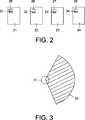
Ausführungsbeispiele der Erfindung sind exemplarisch in den beigefügten schematischen Zeichnungen dargestellt. Es zeigen:Embodiments of the invention are illustrated by way of example in the accompanying schematic drawings. Show it:
Die
Jede der Achsen
Im Falle des vorliegenden Ausführungsbeispiels ist der Steuerrechner
Im Falle des vorliegenden Ausführungsbeispiels ist es vorgesehen, dass der Steuerrechner
Damit im Falle des vorliegenden Ausführungsbeispiels der Steuerrechner
Im Falle des vorliegenden Ausführungsbeispiels sind in jedem der Transponder
Ferner ist im Falle des vorliegenden Ausführungsbeispiels am Flansch
Wird nun eines der Werkzeuge
Der Steuerrechner
Die Ermittlung und Einstellung des dem Werkzeug
Es ist ebenso möglich über einen sicheren Rückkanal vom Steuerrechner
Anstelle einer Speicherung der für das Einstellen des Arbeitsbereichs
Ist keine Information über das Werkzeug
Die Steuervorrichtung
The
Es ist aber auch möglich, dass der Roboter R das an seinem Flansch
Sowohl das Anfahren der Posen (Achsenstellungen S1–S3) als auch das Bestimmen und/oder die Berechnung der Drehmomente geschieht dabei vorzugsweise in sicherer Technik. Aus dieser Information können nun (ebenfalls in sicherer Technik) die Lastparameter (Masse und Schwerpunkt) des am Roboter R befestigten Werkzeugs berechnet und der relevante Arbeitsbereich
Claims (14)
Translated fromGermanPriority Applications (7)
| Application Number | Priority Date | Filing Date | Title |
|---|---|---|---|
| DE102008001664.0ADE102008001664B4 (en) | 2008-05-08 | 2008-05-08 | Medical robot and method for meeting the performance requirement of a medical robot |
| JP2011507890AJP5325976B2 (en) | 2008-05-08 | 2009-05-05 | Medical robot and method for meeting performance requirements of medical robot |
| EP09742053AEP2271466B1 (en) | 2008-05-08 | 2009-05-05 | Medical robot and method for meeting the performance requirements of a medical robot |
| AT09742053TATE539852T1 (en) | 2008-05-08 | 2009-05-05 | MEDICAL ROBOT AND METHOD FOR FULFILLING THE PERFORMANCE REQUIREMENTS OF A MEDICAL ROBOT |
| PCT/EP2009/055408WO2009135835A1 (en) | 2008-05-08 | 2009-05-05 | Medical robot and method for meeting the performance requirements of a medical robot |
| US12/991,196US8831779B2 (en) | 2008-05-08 | 2009-05-05 | Medical robot and method for meeting the performance requirements of a medical robot |
| KR1020107025568AKR20110007193A (en) | 2008-05-08 | 2009-05-05 | Medical Robots, and Methods to Meet the Performance Needs of Medical Robots |
Applications Claiming Priority (1)
| Application Number | Priority Date | Filing Date | Title |
|---|---|---|---|
| DE102008001664.0ADE102008001664B4 (en) | 2008-05-08 | 2008-05-08 | Medical robot and method for meeting the performance requirement of a medical robot |
Publications (2)
| Publication Number | Publication Date |
|---|---|
| DE102008001664A1 DE102008001664A1 (en) | 2009-11-19 |
| DE102008001664B4true DE102008001664B4 (en) | 2015-07-30 |
Family
ID=41059725
Family Applications (1)
| Application Number | Title | Priority Date | Filing Date |
|---|---|---|---|
| DE102008001664.0AExpired - Fee RelatedDE102008001664B4 (en) | 2008-05-08 | 2008-05-08 | Medical robot and method for meeting the performance requirement of a medical robot |
Country Status (7)
| Country | Link |
|---|---|
| US (1) | US8831779B2 (en) |
| EP (1) | EP2271466B1 (en) |
| JP (1) | JP5325976B2 (en) |
| KR (1) | KR20110007193A (en) |
| AT (1) | ATE539852T1 (en) |
| DE (1) | DE102008001664B4 (en) |
| WO (1) | WO2009135835A1 (en) |
Cited By (3)
| Publication number | Priority date | Publication date | Assignee | Title |
|---|---|---|---|---|
| US20190321990A1 (en)* | 2018-04-24 | 2019-10-24 | Fanuc Corporation | Device, method and program for estimating weight and position of gravity center of load by using robot |
| DE102021212134B3 (en) | 2021-10-27 | 2023-02-02 | Kuka Deutschland Gmbh | Method and system for operating a robot |
| DE102022115462B3 (en) | 2022-06-21 | 2023-07-06 | Deutsches Zentrum für Luft- und Raumfahrt e.V. | Robot manipulator with task null space |
Families Citing this family (395)
| Publication number | Priority date | Publication date | Assignee | Title |
|---|---|---|---|---|
| US20070084897A1 (en) | 2003-05-20 | 2007-04-19 | Shelton Frederick E Iv | Articulating surgical stapling instrument incorporating a two-piece e-beam firing mechanism |
| US9060770B2 (en) | 2003-05-20 | 2015-06-23 | Ethicon Endo-Surgery, Inc. | Robotically-driven surgical instrument with E-beam driver |
| US11890012B2 (en) | 2004-07-28 | 2024-02-06 | Cilag Gmbh International | Staple cartridge comprising cartridge body and attached support |
| US8215531B2 (en) | 2004-07-28 | 2012-07-10 | Ethicon Endo-Surgery, Inc. | Surgical stapling instrument having a medical substance dispenser |
| US11998198B2 (en) | 2004-07-28 | 2024-06-04 | Cilag Gmbh International | Surgical stapling instrument incorporating a two-piece E-beam firing mechanism |
| US9072535B2 (en) | 2011-05-27 | 2015-07-07 | Ethicon Endo-Surgery, Inc. | Surgical stapling instruments with rotatable staple deployment arrangements |
| US11484312B2 (en) | 2005-08-31 | 2022-11-01 | Cilag Gmbh International | Staple cartridge comprising a staple driver arrangement |
| US11246590B2 (en) | 2005-08-31 | 2022-02-15 | Cilag Gmbh International | Staple cartridge including staple drivers having different unfired heights |
| US7934630B2 (en) | 2005-08-31 | 2011-05-03 | Ethicon Endo-Surgery, Inc. | Staple cartridges for forming staples having differing formed staple heights |
| US9237891B2 (en) | 2005-08-31 | 2016-01-19 | Ethicon Endo-Surgery, Inc. | Robotically-controlled surgical stapling devices that produce formed staples having different lengths |
| US10159482B2 (en) | 2005-08-31 | 2018-12-25 | Ethicon Llc | Fastener cartridge assembly comprising a fixed anvil and different staple heights |
| US7669746B2 (en) | 2005-08-31 | 2010-03-02 | Ethicon Endo-Surgery, Inc. | Staple cartridges for forming staples having differing formed staple heights |
| US20070106317A1 (en) | 2005-11-09 | 2007-05-10 | Shelton Frederick E Iv | Hydraulically and electrically actuated articulation joints for surgical instruments |
| US20110295295A1 (en) | 2006-01-31 | 2011-12-01 | Ethicon Endo-Surgery, Inc. | Robotically-controlled surgical instrument having recording capabilities |
| US11278279B2 (en) | 2006-01-31 | 2022-03-22 | Cilag Gmbh International | Surgical instrument assembly |
| US20120292367A1 (en) | 2006-01-31 | 2012-11-22 | Ethicon Endo-Surgery, Inc. | Robotically-controlled end effector |
| US7753904B2 (en) | 2006-01-31 | 2010-07-13 | Ethicon Endo-Surgery, Inc. | Endoscopic surgical instrument with a handle that can articulate with respect to the shaft |
| US7845537B2 (en) | 2006-01-31 | 2010-12-07 | Ethicon Endo-Surgery, Inc. | Surgical instrument having recording capabilities |
| US11224427B2 (en) | 2006-01-31 | 2022-01-18 | Cilag Gmbh International | Surgical stapling system including a console and retraction assembly |
| US11793518B2 (en) | 2006-01-31 | 2023-10-24 | Cilag Gmbh International | Powered surgical instruments with firing system lockout arrangements |
| US8708213B2 (en) | 2006-01-31 | 2014-04-29 | Ethicon Endo-Surgery, Inc. | Surgical instrument having a feedback system |
| US8186555B2 (en) | 2006-01-31 | 2012-05-29 | Ethicon Endo-Surgery, Inc. | Motor-driven surgical cutting and fastening instrument with mechanical closure system |
| US20110024477A1 (en) | 2009-02-06 | 2011-02-03 | Hall Steven G | Driven Surgical Stapler Improvements |
| US8820603B2 (en) | 2006-01-31 | 2014-09-02 | Ethicon Endo-Surgery, Inc. | Accessing data stored in a memory of a surgical instrument |
| US8992422B2 (en) | 2006-03-23 | 2015-03-31 | Ethicon Endo-Surgery, Inc. | Robotically-controlled endoscopic accessory channel |
| US8322455B2 (en) | 2006-06-27 | 2012-12-04 | Ethicon Endo-Surgery, Inc. | Manually driven surgical cutting and fastening instrument |
| US10568652B2 (en) | 2006-09-29 | 2020-02-25 | Ethicon Llc | Surgical staples having attached drivers of different heights and stapling instruments for deploying the same |
| US11980366B2 (en) | 2006-10-03 | 2024-05-14 | Cilag Gmbh International | Surgical instrument |
| US11291441B2 (en) | 2007-01-10 | 2022-04-05 | Cilag Gmbh International | Surgical instrument with wireless communication between control unit and remote sensor |
| US8684253B2 (en) | 2007-01-10 | 2014-04-01 | Ethicon Endo-Surgery, Inc. | Surgical instrument with wireless communication between a control unit of a robotic system and remote sensor |
| US8632535B2 (en) | 2007-01-10 | 2014-01-21 | Ethicon Endo-Surgery, Inc. | Interlock and surgical instrument including same |
| US11039836B2 (en) | 2007-01-11 | 2021-06-22 | Cilag Gmbh International | Staple cartridge for use with a surgical stapling instrument |
| US20080169333A1 (en) | 2007-01-11 | 2008-07-17 | Shelton Frederick E | Surgical stapler end effector with tapered distal end |
| US7673782B2 (en) | 2007-03-15 | 2010-03-09 | Ethicon Endo-Surgery, Inc. | Surgical stapling instrument having a releasable buttress material |
| US8931682B2 (en) | 2007-06-04 | 2015-01-13 | Ethicon Endo-Surgery, Inc. | Robotically-controlled shaft based rotary drive systems for surgical instruments |
| US11564682B2 (en) | 2007-06-04 | 2023-01-31 | Cilag Gmbh International | Surgical stapler device |
| US7753245B2 (en) | 2007-06-22 | 2010-07-13 | Ethicon Endo-Surgery, Inc. | Surgical stapling instruments |
| US11849941B2 (en) | 2007-06-29 | 2023-12-26 | Cilag Gmbh International | Staple cartridge having staple cavities extending at a transverse angle relative to a longitudinal cartridge axis |
| US7866527B2 (en) | 2008-02-14 | 2011-01-11 | Ethicon Endo-Surgery, Inc. | Surgical stapling apparatus with interlockable firing system |
| US8758391B2 (en) | 2008-02-14 | 2014-06-24 | Ethicon Endo-Surgery, Inc. | Interchangeable tools for surgical instruments |
| US8573465B2 (en) | 2008-02-14 | 2013-11-05 | Ethicon Endo-Surgery, Inc. | Robotically-controlled surgical end effector system with rotary actuated closure systems |
| US9179912B2 (en) | 2008-02-14 | 2015-11-10 | Ethicon Endo-Surgery, Inc. | Robotically-controlled motorized surgical cutting and fastening instrument |
| US7819298B2 (en) | 2008-02-14 | 2010-10-26 | Ethicon Endo-Surgery, Inc. | Surgical stapling apparatus with control features operable with one hand |
| US11986183B2 (en) | 2008-02-14 | 2024-05-21 | Cilag Gmbh International | Surgical cutting and fastening instrument comprising a plurality of sensors to measure an electrical parameter |
| JP5410110B2 (en) | 2008-02-14 | 2014-02-05 | エシコン・エンド−サージェリィ・インコーポレイテッド | Surgical cutting / fixing instrument with RF electrode |
| US8636736B2 (en) | 2008-02-14 | 2014-01-28 | Ethicon Endo-Surgery, Inc. | Motorized surgical cutting and fastening instrument |
| US9585657B2 (en) | 2008-02-15 | 2017-03-07 | Ethicon Endo-Surgery, Llc | Actuator for releasing a layer of material from a surgical end effector |
| US9005230B2 (en) | 2008-09-23 | 2015-04-14 | Ethicon Endo-Surgery, Inc. | Motorized surgical instrument |
| US8210411B2 (en) | 2008-09-23 | 2012-07-03 | Ethicon Endo-Surgery, Inc. | Motor-driven surgical cutting instrument |
| US9386983B2 (en) | 2008-09-23 | 2016-07-12 | Ethicon Endo-Surgery, Llc | Robotically-controlled motorized surgical instrument |
| US11648005B2 (en) | 2008-09-23 | 2023-05-16 | Cilag Gmbh International | Robotically-controlled motorized surgical instrument with an end effector |
| US8608045B2 (en) | 2008-10-10 | 2013-12-17 | Ethicon Endo-Sugery, Inc. | Powered surgical cutting and stapling apparatus with manually retractable firing system |
| US8517239B2 (en) | 2009-02-05 | 2013-08-27 | Ethicon Endo-Surgery, Inc. | Surgical stapling instrument comprising a magnetic element driver |
| RU2525225C2 (en) | 2009-02-06 | 2014-08-10 | Этикон Эндо-Серджери, Инк. | Improvement of drive surgical suturing instrument |
| US11090104B2 (en) | 2009-10-09 | 2021-08-17 | Cilag Gmbh International | Surgical generator for ultrasonic and electrosurgical devices |
| US8851354B2 (en) | 2009-12-24 | 2014-10-07 | Ethicon Endo-Surgery, Inc. | Surgical cutting instrument that analyzes tissue thickness |
| US8220688B2 (en) | 2009-12-24 | 2012-07-17 | Ethicon Endo-Surgery, Inc. | Motor-driven surgical cutting instrument with electric actuator directional control assembly |
| US8783543B2 (en) | 2010-07-30 | 2014-07-22 | Ethicon Endo-Surgery, Inc. | Tissue acquisition arrangements and methods for surgical stapling devices |
| US9386988B2 (en) | 2010-09-30 | 2016-07-12 | Ethicon End-Surgery, LLC | Retainer assembly including a tissue thickness compensator |
| US12213666B2 (en) | 2010-09-30 | 2025-02-04 | Cilag Gmbh International | Tissue thickness compensator comprising layers |
| US11925354B2 (en) | 2010-09-30 | 2024-03-12 | Cilag Gmbh International | Staple cartridge comprising staples positioned within a compressible portion thereof |
| US9788834B2 (en) | 2010-09-30 | 2017-10-17 | Ethicon Llc | Layer comprising deployable attachment members |
| US10945731B2 (en) | 2010-09-30 | 2021-03-16 | Ethicon Llc | Tissue thickness compensator comprising controlled release and expansion |
| US11298125B2 (en) | 2010-09-30 | 2022-04-12 | Cilag Gmbh International | Tissue stapler having a thickness compensator |
| US9351730B2 (en) | 2011-04-29 | 2016-05-31 | Ethicon Endo-Surgery, Llc | Tissue thickness compensator comprising channels |
| US9016542B2 (en) | 2010-09-30 | 2015-04-28 | Ethicon Endo-Surgery, Inc. | Staple cartridge comprising compressible distortion resistant components |
| US9629814B2 (en) | 2010-09-30 | 2017-04-25 | Ethicon Endo-Surgery, Llc | Tissue thickness compensator configured to redistribute compressive forces |
| US11812965B2 (en) | 2010-09-30 | 2023-11-14 | Cilag Gmbh International | Layer of material for a surgical end effector |
| US8695866B2 (en) | 2010-10-01 | 2014-04-15 | Ethicon Endo-Surgery, Inc. | Surgical instrument having a power control circuit |
| JP5839929B2 (en)* | 2010-11-19 | 2016-01-06 | キヤノン株式会社 | Information processing apparatus, information processing system, information processing method, and program |
| WO2012074564A1 (en) | 2010-12-02 | 2012-06-07 | Freehand Endoscopic Devices, Inc. | Surgical tool |
| US9119655B2 (en) | 2012-08-03 | 2015-09-01 | Stryker Corporation | Surgical manipulator capable of controlling a surgical instrument in multiple modes |
| US9921712B2 (en) | 2010-12-29 | 2018-03-20 | Mako Surgical Corp. | System and method for providing substantially stable control of a surgical tool |
| DE102011008856A1 (en)* | 2011-01-18 | 2012-07-19 | Fresenius Medical Care Deutschland Gmbh | Method for carrying out a query of a specification feature of a medical-technical functional device, medical-technical functional device, medical-technical treatment device and control device |
| AU2012250197B2 (en) | 2011-04-29 | 2017-08-10 | Ethicon Endo-Surgery, Inc. | Staple cartridge comprising staples positioned within a compressible portion thereof |
| US11207064B2 (en) | 2011-05-27 | 2021-12-28 | Cilag Gmbh International | Automated end effector component reloading system for use with a robotic system |
| US9437005B2 (en)* | 2011-07-08 | 2016-09-06 | Canon Kabushiki Kaisha | Information processing apparatus and information processing method |
| EP2737375B1 (en)* | 2011-07-27 | 2016-11-16 | ABB Schweiz AG | System for commanding a robot |
| JP6224070B2 (en) | 2012-03-28 | 2017-11-01 | エシコン・エンド−サージェリィ・インコーポレイテッドEthicon Endo−Surgery,Inc. | Retainer assembly including tissue thickness compensator |
| BR112014024098B1 (en) | 2012-03-28 | 2021-05-25 | Ethicon Endo-Surgery, Inc. | staple cartridge |
| MX358135B (en) | 2012-03-28 | 2018-08-06 | Ethicon Endo Surgery Inc | Tissue thickness compensator comprising a plurality of layers. |
| US9101358B2 (en) | 2012-06-15 | 2015-08-11 | Ethicon Endo-Surgery, Inc. | Articulatable surgical instrument comprising a firing drive |
| US11278284B2 (en) | 2012-06-28 | 2022-03-22 | Cilag Gmbh International | Rotary drive arrangements for surgical instruments |
| JP6290201B2 (en) | 2012-06-28 | 2018-03-07 | エシコン・エンド−サージェリィ・インコーポレイテッドEthicon Endo−Surgery,Inc. | Lockout for empty clip cartridge |
| US20140001231A1 (en) | 2012-06-28 | 2014-01-02 | Ethicon Endo-Surgery, Inc. | Firing system lockout arrangements for surgical instruments |
| BR112014032776B1 (en) | 2012-06-28 | 2021-09-08 | Ethicon Endo-Surgery, Inc | SURGICAL INSTRUMENT SYSTEM AND SURGICAL KIT FOR USE WITH A SURGICAL INSTRUMENT SYSTEM |
| US9408606B2 (en) | 2012-06-28 | 2016-08-09 | Ethicon Endo-Surgery, Llc | Robotically powered surgical device with manually-actuatable reversing system |
| US9282974B2 (en) | 2012-06-28 | 2016-03-15 | Ethicon Endo-Surgery, Llc | Empty clip cartridge lockout |
| US9289256B2 (en) | 2012-06-28 | 2016-03-22 | Ethicon Endo-Surgery, Llc | Surgical end effectors having angled tissue-contacting surfaces |
| US12383267B2 (en) | 2012-06-28 | 2025-08-12 | Cilag Gmbh International | Robotically powered surgical device with manually-actuatable reversing system |
| CN107198567B (en) | 2012-08-03 | 2021-02-09 | 史赛克公司 | Systems and methods for robotic surgery |
| US9820818B2 (en) | 2012-08-03 | 2017-11-21 | Stryker Corporation | System and method for controlling a surgical manipulator based on implant parameters |
| US9226796B2 (en) | 2012-08-03 | 2016-01-05 | Stryker Corporation | Method for detecting a disturbance as an energy applicator of a surgical instrument traverses a cutting path |
| WO2014043702A1 (en) | 2012-09-17 | 2014-03-20 | Rethink Robotics, Inc. | Constraining robotic manipulators with redundant degrees of freedom |
| JP2014140913A (en)* | 2013-01-22 | 2014-08-07 | Jtekt Corp | Robot control device, robot control system, and robot control method |
| BR112015021082B1 (en) | 2013-03-01 | 2022-05-10 | Ethicon Endo-Surgery, Inc | surgical instrument |
| RU2672520C2 (en) | 2013-03-01 | 2018-11-15 | Этикон Эндо-Серджери, Инк. | Hingedly turnable surgical instruments with conducting ways for signal transfer |
| US9808244B2 (en) | 2013-03-14 | 2017-11-07 | Ethicon Llc | Sensor arrangements for absolute positioning system for surgical instruments |
| US9629629B2 (en) | 2013-03-14 | 2017-04-25 | Ethicon Endo-Surgey, LLC | Control systems for surgical instruments |
| US9826976B2 (en) | 2013-04-16 | 2017-11-28 | Ethicon Llc | Motor driven surgical instruments with lockable dual drive shafts |
| BR112015026109B1 (en) | 2013-04-16 | 2022-02-22 | Ethicon Endo-Surgery, Inc | surgical instrument |
| MX369362B (en) | 2013-08-23 | 2019-11-06 | Ethicon Endo Surgery Llc | Firing member retraction devices for powered surgical instruments. |
| US9775609B2 (en) | 2013-08-23 | 2017-10-03 | Ethicon Llc | Tamper proof circuit for surgical instrument battery pack |
| US9962161B2 (en) | 2014-02-12 | 2018-05-08 | Ethicon Llc | Deliverable surgical instrument |
| US12232723B2 (en) | 2014-03-26 | 2025-02-25 | Cilag Gmbh International | Systems and methods for controlling a segmented circuit |
| US20150272580A1 (en) | 2014-03-26 | 2015-10-01 | Ethicon Endo-Surgery, Inc. | Verification of number of battery exchanges/procedure count |
| US10004497B2 (en) | 2014-03-26 | 2018-06-26 | Ethicon Llc | Interface systems for use with surgical instruments |
| US10013049B2 (en) | 2014-03-26 | 2018-07-03 | Ethicon Llc | Power management through sleep options of segmented circuit and wake up control |
| BR112016021943B1 (en) | 2014-03-26 | 2022-06-14 | Ethicon Endo-Surgery, Llc | SURGICAL INSTRUMENT FOR USE BY AN OPERATOR IN A SURGICAL PROCEDURE |
| BR112016023825B1 (en) | 2014-04-16 | 2022-08-02 | Ethicon Endo-Surgery, Llc | STAPLE CARTRIDGE FOR USE WITH A SURGICAL STAPLER AND STAPLE CARTRIDGE FOR USE WITH A SURGICAL INSTRUMENT |
| US10470768B2 (en) | 2014-04-16 | 2019-11-12 | Ethicon Llc | Fastener cartridge including a layer attached thereto |
| CN106456176B (en) | 2014-04-16 | 2019-06-28 | 伊西康内外科有限责任公司 | Fastener Cartridge Including Extensions With Different Configurations |
| US20150297225A1 (en) | 2014-04-16 | 2015-10-22 | Ethicon Endo-Surgery, Inc. | Fastener cartridges including extensions having different configurations |
| CN106456159B (en) | 2014-04-16 | 2019-03-08 | 伊西康内外科有限责任公司 | Fastener Cartridge Assembly and Nail Retainer Cover Arrangement |
| US10327764B2 (en) | 2014-09-26 | 2019-06-25 | Ethicon Llc | Method for creating a flexible staple line |
| NL2013369B1 (en)* | 2014-08-26 | 2016-09-26 | Univ Eindhoven Tech | Surgical robotic system and control of surgical robotic system. |
| BR112017004361B1 (en) | 2014-09-05 | 2023-04-11 | Ethicon Llc | ELECTRONIC SYSTEM FOR A SURGICAL INSTRUMENT |
| US10135242B2 (en) | 2014-09-05 | 2018-11-20 | Ethicon Llc | Smart cartridge wake up operation and data retention |
| US11311294B2 (en) | 2014-09-05 | 2022-04-26 | Cilag Gmbh International | Powered medical device including measurement of closure state of jaws |
| US10105142B2 (en) | 2014-09-18 | 2018-10-23 | Ethicon Llc | Surgical stapler with plurality of cutting elements |
| CN107427300B (en) | 2014-09-26 | 2020-12-04 | 伊西康有限责任公司 | Surgical suture buttresses and auxiliary materials |
| US11523821B2 (en) | 2014-09-26 | 2022-12-13 | Cilag Gmbh International | Method for creating a flexible staple line |
| US9924944B2 (en) | 2014-10-16 | 2018-03-27 | Ethicon Llc | Staple cartridge comprising an adjunct material |
| JP5896003B1 (en)* | 2014-10-29 | 2016-03-30 | 株式会社安川電機 | Processing apparatus, teaching method, workpiece production method, controller, and control method |
| JP2016087705A (en)* | 2014-10-29 | 2016-05-23 | 株式会社安川電機 | Processing device and work production method |
| US10517594B2 (en) | 2014-10-29 | 2019-12-31 | Ethicon Llc | Cartridge assemblies for surgical staplers |
| US11141153B2 (en) | 2014-10-29 | 2021-10-12 | Cilag Gmbh International | Staple cartridges comprising driver arrangements |
| WO2016067689A1 (en) | 2014-10-29 | 2016-05-06 | 株式会社安川電機 | Machining device and production method of workpiece |
| US9844376B2 (en) | 2014-11-06 | 2017-12-19 | Ethicon Llc | Staple cartridge comprising a releasable adjunct material |
| US10736636B2 (en) | 2014-12-10 | 2020-08-11 | Ethicon Llc | Articulatable surgical instrument system |
| MX389118B (en) | 2014-12-18 | 2025-03-20 | Ethicon Llc | SURGICAL INSTRUMENT WITH AN ANVIL THAT CAN BE SELECTIVELY MOVED ON A DISCRETE, NON-MOBILE AXIS RELATIVE TO A STAPLE CARTRIDGE. |
| US10085748B2 (en) | 2014-12-18 | 2018-10-02 | Ethicon Llc | Locking arrangements for detachable shaft assemblies with articulatable surgical end effectors |
| US9943309B2 (en) | 2014-12-18 | 2018-04-17 | Ethicon Llc | Surgical instruments with articulatable end effectors and movable firing beam support arrangements |
| US9844375B2 (en) | 2014-12-18 | 2017-12-19 | Ethicon Llc | Drive arrangements for articulatable surgical instruments |
| US9844374B2 (en) | 2014-12-18 | 2017-12-19 | Ethicon Llc | Surgical instrument systems comprising an articulatable end effector and means for adjusting the firing stroke of a firing member |
| US9987000B2 (en) | 2014-12-18 | 2018-06-05 | Ethicon Llc | Surgical instrument assembly comprising a flexible articulation system |
| US11154301B2 (en) | 2015-02-27 | 2021-10-26 | Cilag Gmbh International | Modular stapling assembly |
| JP5975129B1 (en) | 2015-03-02 | 2016-08-23 | 株式会社安川電機 | robot |
| US10441279B2 (en) | 2015-03-06 | 2019-10-15 | Ethicon Llc | Multiple level thresholds to modify operation of powered surgical instruments |
| US9901342B2 (en) | 2015-03-06 | 2018-02-27 | Ethicon Endo-Surgery, Llc | Signal and power communication system positioned on a rotatable shaft |
| US9993248B2 (en) | 2015-03-06 | 2018-06-12 | Ethicon Endo-Surgery, Llc | Smart sensors with local signal processing |
| US10548504B2 (en) | 2015-03-06 | 2020-02-04 | Ethicon Llc | Overlaid multi sensor radio frequency (RF) electrode system to measure tissue compression |
| JP2020121162A (en) | 2015-03-06 | 2020-08-13 | エシコン エルエルシーEthicon LLC | Time dependent evaluation of sensor data to determine stability element, creep element and viscoelastic element of measurement |
| US10245033B2 (en) | 2015-03-06 | 2019-04-02 | Ethicon Llc | Surgical instrument comprising a lockable battery housing |
| US10433844B2 (en) | 2015-03-31 | 2019-10-08 | Ethicon Llc | Surgical instrument with selectively disengageable threaded drive systems |
| JP6464945B2 (en)* | 2015-07-03 | 2019-02-06 | 株式会社デンソーウェーブ | Robot system |
| US10835249B2 (en) | 2015-08-17 | 2020-11-17 | Ethicon Llc | Implantable layers for a surgical instrument |
| US10238386B2 (en) | 2015-09-23 | 2019-03-26 | Ethicon Llc | Surgical stapler having motor control based on an electrical parameter related to a motor current |
| US10105139B2 (en) | 2015-09-23 | 2018-10-23 | Ethicon Llc | Surgical stapler having downstream current-based motor control |
| US10299878B2 (en) | 2015-09-25 | 2019-05-28 | Ethicon Llc | Implantable adjunct systems for determining adjunct skew |
| US10478188B2 (en) | 2015-09-30 | 2019-11-19 | Ethicon Llc | Implantable layer comprising a constricted configuration |
| US11890015B2 (en) | 2015-09-30 | 2024-02-06 | Cilag Gmbh International | Compressible adjunct with crossing spacer fibers |
| US10433846B2 (en) | 2015-09-30 | 2019-10-08 | Ethicon Llc | Compressible adjunct with crossing spacer fibers |
| US10980539B2 (en) | 2015-09-30 | 2021-04-20 | Ethicon Llc | Implantable adjunct comprising bonded layers |
| US10292704B2 (en) | 2015-12-30 | 2019-05-21 | Ethicon Llc | Mechanisms for compensating for battery pack failure in powered surgical instruments |
| US10265068B2 (en) | 2015-12-30 | 2019-04-23 | Ethicon Llc | Surgical instruments with separable motors and motor control circuits |
| US10368865B2 (en) | 2015-12-30 | 2019-08-06 | Ethicon Llc | Mechanisms for compensating for drivetrain failure in powered surgical instruments |
| US11129670B2 (en) | 2016-01-15 | 2021-09-28 | Cilag Gmbh International | Modular battery powered handheld surgical instrument with selective application of energy based on button displacement, intensity, or local tissue characterization |
| US11051840B2 (en) | 2016-01-15 | 2021-07-06 | Ethicon Llc | Modular battery powered handheld surgical instrument with reusable asymmetric handle housing |
| BR112018016098B1 (en) | 2016-02-09 | 2023-02-23 | Ethicon Llc | SURGICAL INSTRUMENT |
| US11213293B2 (en) | 2016-02-09 | 2022-01-04 | Cilag Gmbh International | Articulatable surgical instruments with single articulation link arrangements |
| US10448948B2 (en) | 2016-02-12 | 2019-10-22 | Ethicon Llc | Mechanisms for compensating for drivetrain failure in powered surgical instruments |
| US11224426B2 (en) | 2016-02-12 | 2022-01-18 | Cilag Gmbh International | Mechanisms for compensating for drivetrain failure in powered surgical instruments |
| US11607239B2 (en) | 2016-04-15 | 2023-03-21 | Cilag Gmbh International | Systems and methods for controlling a surgical stapling and cutting instrument |
| US11179150B2 (en) | 2016-04-15 | 2021-11-23 | Cilag Gmbh International | Systems and methods for controlling a surgical stapling and cutting instrument |
| US10426467B2 (en) | 2016-04-15 | 2019-10-01 | Ethicon Llc | Surgical instrument with detection sensors |
| US10357247B2 (en) | 2016-04-15 | 2019-07-23 | Ethicon Llc | Surgical instrument with multiple program responses during a firing motion |
| US10335145B2 (en) | 2016-04-15 | 2019-07-02 | Ethicon Llc | Modular surgical instrument with configurable operating mode |
| US10456137B2 (en) | 2016-04-15 | 2019-10-29 | Ethicon Llc | Staple formation detection mechanisms |
| US10828028B2 (en) | 2016-04-15 | 2020-11-10 | Ethicon Llc | Surgical instrument with multiple program responses during a firing motion |
| US10492783B2 (en) | 2016-04-15 | 2019-12-03 | Ethicon, Llc | Surgical instrument with improved stop/start control during a firing motion |
| US10363037B2 (en) | 2016-04-18 | 2019-07-30 | Ethicon Llc | Surgical instrument system comprising a magnetic lockout |
| US20170296173A1 (en) | 2016-04-18 | 2017-10-19 | Ethicon Endo-Surgery, Llc | Method for operating a surgical instrument |
| US11317917B2 (en) | 2016-04-18 | 2022-05-03 | Cilag Gmbh International | Surgical stapling system comprising a lockable firing assembly |
| US10500000B2 (en) | 2016-08-16 | 2019-12-10 | Ethicon Llc | Surgical tool with manual control of end effector jaws |
| US11266430B2 (en) | 2016-11-29 | 2022-03-08 | Cilag Gmbh International | End effector control and calibration |
| US11202682B2 (en) | 2016-12-16 | 2021-12-21 | Mako Surgical Corp. | Techniques for modifying tool operation in a surgical robotic system based on comparing actual and commanded states of the tool relative to a surgical site |
| US10813638B2 (en) | 2016-12-21 | 2020-10-27 | Ethicon Llc | Surgical end effectors with expandable tissue stop arrangements |
| US10542982B2 (en) | 2016-12-21 | 2020-01-28 | Ethicon Llc | Shaft assembly comprising first and second articulation lockouts |
| US10898186B2 (en) | 2016-12-21 | 2021-01-26 | Ethicon Llc | Staple forming pocket arrangements comprising primary sidewalls and pocket sidewalls |
| US10582928B2 (en) | 2016-12-21 | 2020-03-10 | Ethicon Llc | Articulation lock arrangements for locking an end effector in an articulated position in response to actuation of a jaw closure system |
| US10973516B2 (en) | 2016-12-21 | 2021-04-13 | Ethicon Llc | Surgical end effectors and adaptable firing members therefor |
| JP7010956B2 (en) | 2016-12-21 | 2022-01-26 | エシコン エルエルシー | How to staple tissue |
| CN110087565A (en) | 2016-12-21 | 2019-08-02 | 爱惜康有限责任公司 | Surgical stapling system |
| US11134942B2 (en) | 2016-12-21 | 2021-10-05 | Cilag Gmbh International | Surgical stapling instruments and staple-forming anvils |
| US10568625B2 (en) | 2016-12-21 | 2020-02-25 | Ethicon Llc | Staple cartridges and arrangements of staples and staple cavities therein |
| JP2020501815A (en) | 2016-12-21 | 2020-01-23 | エシコン エルエルシーEthicon LLC | Surgical stapling system |
| MX2019007295A (en) | 2016-12-21 | 2019-10-15 | Ethicon Llc | Surgical instrument system comprising an end effector lockout and a firing assembly lockout. |
| US10980536B2 (en) | 2016-12-21 | 2021-04-20 | Ethicon Llc | No-cartridge and spent cartridge lockout arrangements for surgical staplers |
| US20180168615A1 (en) | 2016-12-21 | 2018-06-21 | Ethicon Endo-Surgery, Llc | Method of deforming staples from two different types of staple cartridges with the same surgical stapling instrument |
| JP6983893B2 (en) | 2016-12-21 | 2021-12-17 | エシコン エルエルシーEthicon LLC | Lockout configuration for surgical end effectors and replaceable tool assemblies |
| JP7010957B2 (en) | 2016-12-21 | 2022-01-26 | エシコン エルエルシー | Shaft assembly with lockout |
| US20180168625A1 (en) | 2016-12-21 | 2018-06-21 | Ethicon Endo-Surgery, Llc | Surgical stapling instruments with smart staple cartridges |
| US11090048B2 (en) | 2016-12-21 | 2021-08-17 | Cilag Gmbh International | Method for resetting a fuse of a surgical instrument shaft |
| US10485543B2 (en) | 2016-12-21 | 2019-11-26 | Ethicon Llc | Anvil having a knife slot width |
| US11419606B2 (en) | 2016-12-21 | 2022-08-23 | Cilag Gmbh International | Shaft assembly comprising a clutch configured to adapt the output of a rotary firing member to two different systems |
| USD879809S1 (en) | 2017-06-20 | 2020-03-31 | Ethicon Llc | Display panel with changeable graphical user interface |
| US10881399B2 (en) | 2017-06-20 | 2021-01-05 | Ethicon Llc | Techniques for adaptive control of motor velocity of a surgical stapling and cutting instrument |
| US10980537B2 (en) | 2017-06-20 | 2021-04-20 | Ethicon Llc | Closed loop feedback control of motor velocity of a surgical stapling and cutting instrument based on measured time over a specified number of shaft rotations |
| US10779820B2 (en) | 2017-06-20 | 2020-09-22 | Ethicon Llc | Systems and methods for controlling motor speed according to user input for a surgical instrument |
| US11090046B2 (en) | 2017-06-20 | 2021-08-17 | Cilag Gmbh International | Systems and methods for controlling displacement member motion of a surgical stapling and cutting instrument |
| US11071554B2 (en) | 2017-06-20 | 2021-07-27 | Cilag Gmbh International | Closed loop feedback control of motor velocity of a surgical stapling and cutting instrument based on magnitude of velocity error measurements |
| US10307170B2 (en) | 2017-06-20 | 2019-06-04 | Ethicon Llc | Method for closed loop control of motor velocity of a surgical stapling and cutting instrument |
| US11382638B2 (en) | 2017-06-20 | 2022-07-12 | Cilag Gmbh International | Closed loop feedback control of motor velocity of a surgical stapling and cutting instrument based on measured time over a specified displacement distance |
| US10888321B2 (en) | 2017-06-20 | 2021-01-12 | Ethicon Llc | Systems and methods for controlling velocity of a displacement member of a surgical stapling and cutting instrument |
| US11653914B2 (en) | 2017-06-20 | 2023-05-23 | Cilag Gmbh International | Systems and methods for controlling motor velocity of a surgical stapling and cutting instrument according to articulation angle of end effector |
| US11517325B2 (en) | 2017-06-20 | 2022-12-06 | Cilag Gmbh International | Closed loop feedback control of motor velocity of a surgical stapling and cutting instrument based on measured displacement distance traveled over a specified time interval |
| US11266405B2 (en) | 2017-06-27 | 2022-03-08 | Cilag Gmbh International | Surgical anvil manufacturing methods |
| US11090049B2 (en) | 2017-06-27 | 2021-08-17 | Cilag Gmbh International | Staple forming pocket arrangements |
| US10993716B2 (en) | 2017-06-27 | 2021-05-04 | Ethicon Llc | Surgical anvil arrangements |
| US11324503B2 (en) | 2017-06-27 | 2022-05-10 | Cilag Gmbh International | Surgical firing member arrangements |
| US11564686B2 (en) | 2017-06-28 | 2023-01-31 | Cilag Gmbh International | Surgical shaft assemblies with flexible interfaces |
| US11246592B2 (en) | 2017-06-28 | 2022-02-15 | Cilag Gmbh International | Surgical instrument comprising an articulation system lockable to a frame |
| US10758232B2 (en) | 2017-06-28 | 2020-09-01 | Ethicon Llc | Surgical instrument with positive jaw opening features |
| US11484310B2 (en) | 2017-06-28 | 2022-11-01 | Cilag Gmbh International | Surgical instrument comprising a shaft including a closure tube profile |
| US10903685B2 (en) | 2017-06-28 | 2021-01-26 | Ethicon Llc | Surgical shaft assemblies with slip ring assemblies forming capacitive channels |
| US11259805B2 (en) | 2017-06-28 | 2022-03-01 | Cilag Gmbh International | Surgical instrument comprising firing member supports |
| EP3420947B1 (en) | 2017-06-28 | 2022-05-25 | Cilag GmbH International | Surgical instrument comprising selectively actuatable rotatable couplers |
| US10765427B2 (en) | 2017-06-28 | 2020-09-08 | Ethicon Llc | Method for articulating a surgical instrument |
| USD906355S1 (en) | 2017-06-28 | 2020-12-29 | Ethicon Llc | Display screen or portion thereof with a graphical user interface for a surgical instrument |
| US10932772B2 (en) | 2017-06-29 | 2021-03-02 | Ethicon Llc | Methods for closed loop velocity control for robotic surgical instrument |
| US11304695B2 (en) | 2017-08-03 | 2022-04-19 | Cilag Gmbh International | Surgical system shaft interconnection |
| US11944300B2 (en) | 2017-08-03 | 2024-04-02 | Cilag Gmbh International | Method for operating a surgical system bailout |
| US11471155B2 (en) | 2017-08-03 | 2022-10-18 | Cilag Gmbh International | Surgical system bailout |
| US11974742B2 (en) | 2017-08-03 | 2024-05-07 | Cilag Gmbh International | Surgical system comprising an articulation bailout |
| USD917500S1 (en) | 2017-09-29 | 2021-04-27 | Ethicon Llc | Display screen or portion thereof with graphical user interface |
| USD907647S1 (en) | 2017-09-29 | 2021-01-12 | Ethicon Llc | Display screen or portion thereof with animated graphical user interface |
| US11399829B2 (en) | 2017-09-29 | 2022-08-02 | Cilag Gmbh International | Systems and methods of initiating a power shutdown mode for a surgical instrument |
| USD907648S1 (en) | 2017-09-29 | 2021-01-12 | Ethicon Llc | Display screen or portion thereof with animated graphical user interface |
| US10743872B2 (en) | 2017-09-29 | 2020-08-18 | Ethicon Llc | System and methods for controlling a display of a surgical instrument |
| US11090075B2 (en) | 2017-10-30 | 2021-08-17 | Cilag Gmbh International | Articulation features for surgical end effector |
| US11134944B2 (en) | 2017-10-30 | 2021-10-05 | Cilag Gmbh International | Surgical stapler knife motion controls |
| US10842490B2 (en) | 2017-10-31 | 2020-11-24 | Ethicon Llc | Cartridge body design with force reduction based on firing completion |
| US10779825B2 (en) | 2017-12-15 | 2020-09-22 | Ethicon Llc | Adapters with end effector position sensing and control arrangements for use in connection with electromechanical surgical instruments |
| US10743875B2 (en) | 2017-12-15 | 2020-08-18 | Ethicon Llc | Surgical end effectors with jaw stiffener arrangements configured to permit monitoring of firing member |
| US11197670B2 (en) | 2017-12-15 | 2021-12-14 | Cilag Gmbh International | Surgical end effectors with pivotal jaws configured to touch at their respective distal ends when fully closed |
| US11033267B2 (en) | 2017-12-15 | 2021-06-15 | Ethicon Llc | Systems and methods of controlling a clamping member firing rate of a surgical instrument |
| US10828033B2 (en) | 2017-12-15 | 2020-11-10 | Ethicon Llc | Handheld electromechanical surgical instruments with improved motor control arrangements for positioning components of an adapter coupled thereto |
| US10869666B2 (en) | 2017-12-15 | 2020-12-22 | Ethicon Llc | Adapters with control systems for controlling multiple motors of an electromechanical surgical instrument |
| US10779826B2 (en) | 2017-12-15 | 2020-09-22 | Ethicon Llc | Methods of operating surgical end effectors |
| US10966718B2 (en) | 2017-12-15 | 2021-04-06 | Ethicon Llc | Dynamic clamping assemblies with improved wear characteristics for use in connection with electromechanical surgical instruments |
| US11071543B2 (en) | 2017-12-15 | 2021-07-27 | Cilag Gmbh International | Surgical end effectors with clamping assemblies configured to increase jaw aperture ranges |
| US10835330B2 (en) | 2017-12-19 | 2020-11-17 | Ethicon Llc | Method for determining the position of a rotatable jaw of a surgical instrument attachment assembly |
| US10729509B2 (en) | 2017-12-19 | 2020-08-04 | Ethicon Llc | Surgical instrument comprising closure and firing locking mechanism |
| USD910847S1 (en) | 2017-12-19 | 2021-02-16 | Ethicon Llc | Surgical instrument assembly |
| US11020112B2 (en) | 2017-12-19 | 2021-06-01 | Ethicon Llc | Surgical tools configured for interchangeable use with different controller interfaces |
| US11311290B2 (en) | 2017-12-21 | 2022-04-26 | Cilag Gmbh International | Surgical instrument comprising an end effector dampener |
| US11179151B2 (en) | 2017-12-21 | 2021-11-23 | Cilag Gmbh International | Surgical instrument comprising a display |
| US12336705B2 (en) | 2017-12-21 | 2025-06-24 | Cilag Gmbh International | Continuous use self-propelled stapling instrument |
| US11076853B2 (en) | 2017-12-21 | 2021-08-03 | Cilag Gmbh International | Systems and methods of displaying a knife position during transection for a surgical instrument |
| US11129680B2 (en) | 2017-12-21 | 2021-09-28 | Cilag Gmbh International | Surgical instrument comprising a projector |
| US11207065B2 (en) | 2018-08-20 | 2021-12-28 | Cilag Gmbh International | Method for fabricating surgical stapler anvils |
| US11039834B2 (en) | 2018-08-20 | 2021-06-22 | Cilag Gmbh International | Surgical stapler anvils with staple directing protrusions and tissue stability features |
| US10856870B2 (en) | 2018-08-20 | 2020-12-08 | Ethicon Llc | Switching arrangements for motor powered articulatable surgical instruments |
| US20200054321A1 (en) | 2018-08-20 | 2020-02-20 | Ethicon Llc | Surgical instruments with progressive jaw closure arrangements |
| US10912559B2 (en) | 2018-08-20 | 2021-02-09 | Ethicon Llc | Reinforced deformable anvil tip for surgical stapler anvil |
| US11083458B2 (en) | 2018-08-20 | 2021-08-10 | Cilag Gmbh International | Powered surgical instruments with clutching arrangements to convert linear drive motions to rotary drive motions |
| US11324501B2 (en) | 2018-08-20 | 2022-05-10 | Cilag Gmbh International | Surgical stapling devices with improved closure members |
| US11045192B2 (en) | 2018-08-20 | 2021-06-29 | Cilag Gmbh International | Fabricating techniques for surgical stapler anvils |
| US11253256B2 (en) | 2018-08-20 | 2022-02-22 | Cilag Gmbh International | Articulatable motor powered surgical instruments with dedicated articulation motor arrangements |
| US11291440B2 (en) | 2018-08-20 | 2022-04-05 | Cilag Gmbh International | Method for operating a powered articulatable surgical instrument |
| USD914878S1 (en) | 2018-08-20 | 2021-03-30 | Ethicon Llc | Surgical instrument anvil |
| US11172929B2 (en) | 2019-03-25 | 2021-11-16 | Cilag Gmbh International | Articulation drive arrangements for surgical systems |
| US11696761B2 (en) | 2019-03-25 | 2023-07-11 | Cilag Gmbh International | Firing drive arrangements for surgical systems |
| US11147551B2 (en) | 2019-03-25 | 2021-10-19 | Cilag Gmbh International | Firing drive arrangements for surgical systems |
| US11147553B2 (en) | 2019-03-25 | 2021-10-19 | Cilag Gmbh International | Firing drive arrangements for surgical systems |
| US11903581B2 (en) | 2019-04-30 | 2024-02-20 | Cilag Gmbh International | Methods for stapling tissue using a surgical instrument |
| US11471157B2 (en) | 2019-04-30 | 2022-10-18 | Cilag Gmbh International | Articulation control mapping for a surgical instrument |
| US11648009B2 (en) | 2019-04-30 | 2023-05-16 | Cilag Gmbh International | Rotatable jaw tip for a surgical instrument |
| US11253254B2 (en) | 2019-04-30 | 2022-02-22 | Cilag Gmbh International | Shaft rotation actuator on a surgical instrument |
| US11432816B2 (en) | 2019-04-30 | 2022-09-06 | Cilag Gmbh International | Articulation pin for a surgical instrument |
| US11452528B2 (en) | 2019-04-30 | 2022-09-27 | Cilag Gmbh International | Articulation actuators for a surgical instrument |
| US11426251B2 (en) | 2019-04-30 | 2022-08-30 | Cilag Gmbh International | Articulation directional lights on a surgical instrument |
| US11660163B2 (en) | 2019-06-28 | 2023-05-30 | Cilag Gmbh International | Surgical system with RFID tags for updating motor assembly parameters |
| US11241235B2 (en) | 2019-06-28 | 2022-02-08 | Cilag Gmbh International | Method of using multiple RFID chips with a surgical assembly |
| US11298132B2 (en) | 2019-06-28 | 2022-04-12 | Cilag GmbH Inlernational | Staple cartridge including a honeycomb extension |
| US11627959B2 (en) | 2019-06-28 | 2023-04-18 | Cilag Gmbh International | Surgical instruments including manual and powered system lockouts |
| US11553971B2 (en) | 2019-06-28 | 2023-01-17 | Cilag Gmbh International | Surgical RFID assemblies for display and communication |
| US11426167B2 (en) | 2019-06-28 | 2022-08-30 | Cilag Gmbh International | Mechanisms for proper anvil attachment surgical stapling head assembly |
| US11246678B2 (en) | 2019-06-28 | 2022-02-15 | Cilag Gmbh International | Surgical stapling system having a frangible RFID tag |
| US11259803B2 (en) | 2019-06-28 | 2022-03-01 | Cilag Gmbh International | Surgical stapling system having an information encryption protocol |
| US11478241B2 (en) | 2019-06-28 | 2022-10-25 | Cilag Gmbh International | Staple cartridge including projections |
| US11298127B2 (en) | 2019-06-28 | 2022-04-12 | Cilag GmbH Interational | Surgical stapling system having a lockout mechanism for an incompatible cartridge |
| US11051807B2 (en) | 2019-06-28 | 2021-07-06 | Cilag Gmbh International | Packaging assembly including a particulate trap |
| US11291451B2 (en) | 2019-06-28 | 2022-04-05 | Cilag Gmbh International | Surgical instrument with battery compatibility verification functionality |
| US11376098B2 (en) | 2019-06-28 | 2022-07-05 | Cilag Gmbh International | Surgical instrument system comprising an RFID system |
| US11771419B2 (en) | 2019-06-28 | 2023-10-03 | Cilag Gmbh International | Packaging for a replaceable component of a surgical stapling system |
| US11523822B2 (en) | 2019-06-28 | 2022-12-13 | Cilag Gmbh International | Battery pack including a circuit interrupter |
| US11399837B2 (en) | 2019-06-28 | 2022-08-02 | Cilag Gmbh International | Mechanisms for motor control adjustments of a motorized surgical instrument |
| US11497492B2 (en) | 2019-06-28 | 2022-11-15 | Cilag Gmbh International | Surgical instrument including an articulation lock |
| US11684434B2 (en) | 2019-06-28 | 2023-06-27 | Cilag Gmbh International | Surgical RFID assemblies for instrument operational setting control |
| US11638587B2 (en) | 2019-06-28 | 2023-05-02 | Cilag Gmbh International | RFID identification systems for surgical instruments |
| US11224497B2 (en) | 2019-06-28 | 2022-01-18 | Cilag Gmbh International | Surgical systems with multiple RFID tags |
| US11464601B2 (en) | 2019-06-28 | 2022-10-11 | Cilag Gmbh International | Surgical instrument comprising an RFID system for tracking a movable component |
| US12004740B2 (en) | 2019-06-28 | 2024-06-11 | Cilag Gmbh International | Surgical stapling system having an information decryption protocol |
| US11219455B2 (en) | 2019-06-28 | 2022-01-11 | Cilag Gmbh International | Surgical instrument including a lockout key |
| US11464512B2 (en) | 2019-12-19 | 2022-10-11 | Cilag Gmbh International | Staple cartridge comprising a curved deck surface |
| US11911032B2 (en) | 2019-12-19 | 2024-02-27 | Cilag Gmbh International | Staple cartridge comprising a seating cam |
| US11304696B2 (en) | 2019-12-19 | 2022-04-19 | Cilag Gmbh International | Surgical instrument comprising a powered articulation system |
| US11559304B2 (en) | 2019-12-19 | 2023-01-24 | Cilag Gmbh International | Surgical instrument comprising a rapid closure mechanism |
| US11291447B2 (en) | 2019-12-19 | 2022-04-05 | Cilag Gmbh International | Stapling instrument comprising independent jaw closing and staple firing systems |
| US11446029B2 (en) | 2019-12-19 | 2022-09-20 | Cilag Gmbh International | Staple cartridge comprising projections extending from a curved deck surface |
| US11607219B2 (en) | 2019-12-19 | 2023-03-21 | Cilag Gmbh International | Staple cartridge comprising a detachable tissue cutting knife |
| US11234698B2 (en) | 2019-12-19 | 2022-02-01 | Cilag Gmbh International | Stapling system comprising a clamp lockout and a firing lockout |
| US11529139B2 (en) | 2019-12-19 | 2022-12-20 | Cilag Gmbh International | Motor driven surgical instrument |
| US11701111B2 (en) | 2019-12-19 | 2023-07-18 | Cilag Gmbh International | Method for operating a surgical stapling instrument |
| US12035913B2 (en) | 2019-12-19 | 2024-07-16 | Cilag Gmbh International | Staple cartridge comprising a deployable knife |
| US11529137B2 (en) | 2019-12-19 | 2022-12-20 | Cilag Gmbh International | Staple cartridge comprising driver retention members |
| US11576672B2 (en) | 2019-12-19 | 2023-02-14 | Cilag Gmbh International | Surgical instrument comprising a closure system including a closure member and an opening member driven by a drive screw |
| US11931033B2 (en) | 2019-12-19 | 2024-03-19 | Cilag Gmbh International | Staple cartridge comprising a latch lockout |
| US11504122B2 (en) | 2019-12-19 | 2022-11-22 | Cilag Gmbh International | Surgical instrument comprising a nested firing member |
| US11844520B2 (en) | 2019-12-19 | 2023-12-19 | Cilag Gmbh International | Staple cartridge comprising driver retention members |
| CN114901166A (en)* | 2019-12-30 | 2022-08-12 | 西拉格国际有限公司 | Control program for modular combined energy devices |
| US12343063B2 (en) | 2019-12-30 | 2025-07-01 | Cilag Gmbh International | Multi-layer clamp arm pad for enhanced versatility and performance of a surgical device |
| US11937866B2 (en) | 2019-12-30 | 2024-03-26 | Cilag Gmbh International | Method for an electrosurgical procedure |
| US12023086B2 (en) | 2019-12-30 | 2024-07-02 | Cilag Gmbh International | Electrosurgical instrument for delivering blended energy modalities to tissue |
| US12336747B2 (en) | 2019-12-30 | 2025-06-24 | Cilag Gmbh International | Method of operating a combination ultrasonic / bipolar RF surgical device with a combination energy modality end-effector |
| US11786294B2 (en)* | 2019-12-30 | 2023-10-17 | Cilag Gmbh International | Control program for modular combination energy device |
| US20210196357A1 (en) | 2019-12-30 | 2021-07-01 | Ethicon Llc | Electrosurgical instrument with asynchronous energizing electrodes |
| CN111618857B (en)* | 2020-05-28 | 2021-04-20 | 杭州键嘉机器人有限公司 | A Multi-Load Adaptive Gravity Compensation Method for Manipulators |
| USD966512S1 (en) | 2020-06-02 | 2022-10-11 | Cilag Gmbh International | Staple cartridge |
| USD975850S1 (en) | 2020-06-02 | 2023-01-17 | Cilag Gmbh International | Staple cartridge |
| USD975278S1 (en) | 2020-06-02 | 2023-01-10 | Cilag Gmbh International | Staple cartridge |
| USD974560S1 (en) | 2020-06-02 | 2023-01-03 | Cilag Gmbh International | Staple cartridge |
| USD975851S1 (en) | 2020-06-02 | 2023-01-17 | Cilag Gmbh International | Staple cartridge |
| USD976401S1 (en) | 2020-06-02 | 2023-01-24 | Cilag Gmbh International | Staple cartridge |
| USD967421S1 (en) | 2020-06-02 | 2022-10-18 | Cilag Gmbh International | Staple cartridge |
| US11871925B2 (en) | 2020-07-28 | 2024-01-16 | Cilag Gmbh International | Surgical instruments with dual spherical articulation joint arrangements |
| US11452526B2 (en) | 2020-10-29 | 2022-09-27 | Cilag Gmbh International | Surgical instrument comprising a staged voltage regulation start-up system |
| US11534259B2 (en) | 2020-10-29 | 2022-12-27 | Cilag Gmbh International | Surgical instrument comprising an articulation indicator |
| US12053175B2 (en) | 2020-10-29 | 2024-08-06 | Cilag Gmbh International | Surgical instrument comprising a stowed closure actuator stop |
| US11617577B2 (en) | 2020-10-29 | 2023-04-04 | Cilag Gmbh International | Surgical instrument comprising a sensor configured to sense whether an articulation drive of the surgical instrument is actuatable |
| USD980425S1 (en) | 2020-10-29 | 2023-03-07 | Cilag Gmbh International | Surgical instrument assembly |
| USD1013170S1 (en) | 2020-10-29 | 2024-01-30 | Cilag Gmbh International | Surgical instrument assembly |
| US11779330B2 (en) | 2020-10-29 | 2023-10-10 | Cilag Gmbh International | Surgical instrument comprising a jaw alignment system |
| US11931025B2 (en) | 2020-10-29 | 2024-03-19 | Cilag Gmbh International | Surgical instrument comprising a releasable closure drive lock |
| US11517390B2 (en) | 2020-10-29 | 2022-12-06 | Cilag Gmbh International | Surgical instrument comprising a limited travel switch |
| US11717289B2 (en) | 2020-10-29 | 2023-08-08 | Cilag Gmbh International | Surgical instrument comprising an indicator which indicates that an articulation drive is actuatable |
| US11844518B2 (en) | 2020-10-29 | 2023-12-19 | Cilag Gmbh International | Method for operating a surgical instrument |
| US11896217B2 (en) | 2020-10-29 | 2024-02-13 | Cilag Gmbh International | Surgical instrument comprising an articulation lock |
| US11653920B2 (en) | 2020-12-02 | 2023-05-23 | Cilag Gmbh International | Powered surgical instruments with communication interfaces through sterile barrier |
| US11627960B2 (en) | 2020-12-02 | 2023-04-18 | Cilag Gmbh International | Powered surgical instruments with smart reload with separately attachable exteriorly mounted wiring connections |
| US11678882B2 (en) | 2020-12-02 | 2023-06-20 | Cilag Gmbh International | Surgical instruments with interactive features to remedy incidental sled movements |
| US11737751B2 (en) | 2020-12-02 | 2023-08-29 | Cilag Gmbh International | Devices and methods of managing energy dissipated within sterile barriers of surgical instrument housings |
| US11849943B2 (en) | 2020-12-02 | 2023-12-26 | Cilag Gmbh International | Surgical instrument with cartridge release mechanisms |
| US11890010B2 (en) | 2020-12-02 | 2024-02-06 | Cllag GmbH International | Dual-sided reinforced reload for surgical instruments |
| US11653915B2 (en) | 2020-12-02 | 2023-05-23 | Cilag Gmbh International | Surgical instruments with sled location detection and adjustment features |
| US11944296B2 (en) | 2020-12-02 | 2024-04-02 | Cilag Gmbh International | Powered surgical instruments with external connectors |
| US11744581B2 (en) | 2020-12-02 | 2023-09-05 | Cilag Gmbh International | Powered surgical instruments with multi-phase tissue treatment |
| US11751869B2 (en) | 2021-02-26 | 2023-09-12 | Cilag Gmbh International | Monitoring of multiple sensors over time to detect moving characteristics of tissue |
| US11925349B2 (en) | 2021-02-26 | 2024-03-12 | Cilag Gmbh International | Adjustment to transfer parameters to improve available power |
| US11812964B2 (en) | 2021-02-26 | 2023-11-14 | Cilag Gmbh International | Staple cartridge comprising a power management circuit |
| US11696757B2 (en) | 2021-02-26 | 2023-07-11 | Cilag Gmbh International | Monitoring of internal systems to detect and track cartridge motion status |
| US11793514B2 (en) | 2021-02-26 | 2023-10-24 | Cilag Gmbh International | Staple cartridge comprising sensor array which may be embedded in cartridge body |
| US11723657B2 (en) | 2021-02-26 | 2023-08-15 | Cilag Gmbh International | Adjustable communication based on available bandwidth and power capacity |
| US11744583B2 (en) | 2021-02-26 | 2023-09-05 | Cilag Gmbh International | Distal communication array to tune frequency of RF systems |
| US12108951B2 (en) | 2021-02-26 | 2024-10-08 | Cilag Gmbh International | Staple cartridge comprising a sensing array and a temperature control system |
| US11749877B2 (en) | 2021-02-26 | 2023-09-05 | Cilag Gmbh International | Stapling instrument comprising a signal antenna |
| US12324580B2 (en) | 2021-02-26 | 2025-06-10 | Cilag Gmbh International | Method of powering and communicating with a staple cartridge |
| US11950779B2 (en) | 2021-02-26 | 2024-04-09 | Cilag Gmbh International | Method of powering and communicating with a staple cartridge |
| US11950777B2 (en) | 2021-02-26 | 2024-04-09 | Cilag Gmbh International | Staple cartridge comprising an information access control system |
| US11980362B2 (en) | 2021-02-26 | 2024-05-14 | Cilag Gmbh International | Surgical instrument system comprising a power transfer coil |
| US11730473B2 (en) | 2021-02-26 | 2023-08-22 | Cilag Gmbh International | Monitoring of manufacturing life-cycle |
| US11701113B2 (en) | 2021-02-26 | 2023-07-18 | Cilag Gmbh International | Stapling instrument comprising a separate power antenna and a data transfer antenna |
| US11806011B2 (en) | 2021-03-22 | 2023-11-07 | Cilag Gmbh International | Stapling instrument comprising tissue compression systems |
| US11737749B2 (en) | 2021-03-22 | 2023-08-29 | Cilag Gmbh International | Surgical stapling instrument comprising a retraction system |
| US11759202B2 (en) | 2021-03-22 | 2023-09-19 | Cilag Gmbh International | Staple cartridge comprising an implantable layer |
| US11717291B2 (en) | 2021-03-22 | 2023-08-08 | Cilag Gmbh International | Staple cartridge comprising staples configured to apply different tissue compression |
| US11826042B2 (en) | 2021-03-22 | 2023-11-28 | Cilag Gmbh International | Surgical instrument comprising a firing drive including a selectable leverage mechanism |
| US11723658B2 (en) | 2021-03-22 | 2023-08-15 | Cilag Gmbh International | Staple cartridge comprising a firing lockout |
| US11826012B2 (en) | 2021-03-22 | 2023-11-28 | Cilag Gmbh International | Stapling instrument comprising a pulsed motor-driven firing rack |
| US11903582B2 (en) | 2021-03-24 | 2024-02-20 | Cilag Gmbh International | Leveraging surfaces for cartridge installation |
| US11896218B2 (en) | 2021-03-24 | 2024-02-13 | Cilag Gmbh International | Method of using a powered stapling device |
| US12102323B2 (en) | 2021-03-24 | 2024-10-01 | Cilag Gmbh International | Rotary-driven surgical stapling assembly comprising a floatable component |
| US11832816B2 (en) | 2021-03-24 | 2023-12-05 | Cilag Gmbh International | Surgical stapling assembly comprising nonplanar staples and planar staples |
| US11944336B2 (en) | 2021-03-24 | 2024-04-02 | Cilag Gmbh International | Joint arrangements for multi-planar alignment and support of operational drive shafts in articulatable surgical instruments |
| US11793516B2 (en) | 2021-03-24 | 2023-10-24 | Cilag Gmbh International | Surgical staple cartridge comprising longitudinal support beam |
| US11786239B2 (en) | 2021-03-24 | 2023-10-17 | Cilag Gmbh International | Surgical instrument articulation joint arrangements comprising multiple moving linkage features |
| US11849945B2 (en) | 2021-03-24 | 2023-12-26 | Cilag Gmbh International | Rotary-driven surgical stapling assembly comprising eccentrically driven firing member |
| US11857183B2 (en) | 2021-03-24 | 2024-01-02 | Cilag Gmbh International | Stapling assembly components having metal substrates and plastic bodies |
| US11896219B2 (en) | 2021-03-24 | 2024-02-13 | Cilag Gmbh International | Mating features between drivers and underside of a cartridge deck |
| US11744603B2 (en) | 2021-03-24 | 2023-09-05 | Cilag Gmbh International | Multi-axis pivot joints for surgical instruments and methods for manufacturing same |
| US11786243B2 (en) | 2021-03-24 | 2023-10-17 | Cilag Gmbh International | Firing members having flexible portions for adapting to a load during a surgical firing stroke |
| US11849944B2 (en) | 2021-03-24 | 2023-12-26 | Cilag Gmbh International | Drivers for fastener cartridge assemblies having rotary drive screws |
| KR20220152790A (en) | 2021-05-10 | 2022-11-17 | 삼성전자주식회사 | Electronic device and method for controlling the same |
| US11826047B2 (en) | 2021-05-28 | 2023-11-28 | Cilag Gmbh International | Stapling instrument comprising jaw mounts |
| US12082896B2 (en)* | 2021-08-04 | 2024-09-10 | Pixee Medical | Surgical navigation system on wearable computer combining augmented reality and robotics |
| US11980363B2 (en) | 2021-10-18 | 2024-05-14 | Cilag Gmbh International | Row-to-row staple array variations |
| US11957337B2 (en) | 2021-10-18 | 2024-04-16 | Cilag Gmbh International | Surgical stapling assembly with offset ramped drive surfaces |
| US12239317B2 (en) | 2021-10-18 | 2025-03-04 | Cilag Gmbh International | Anvil comprising an arrangement of forming pockets proximal to tissue stop |
| US11877745B2 (en) | 2021-10-18 | 2024-01-23 | Cilag Gmbh International | Surgical stapling assembly having longitudinally-repeating staple leg clusters |
| US12432790B2 (en) | 2021-10-28 | 2025-09-30 | Cilag Gmbh International | Method and device for transmitting UART communications over a security short range wireless communication |
| US12089841B2 (en) | 2021-10-28 | 2024-09-17 | Cilag CmbH International | Staple cartridge identification systems |
| US11937816B2 (en) | 2021-10-28 | 2024-03-26 | Cilag Gmbh International | Electrical lead arrangements for surgical instruments |
| US20240269828A1 (en)* | 2023-02-11 | 2024-08-15 | Ghost Robotics Corporation | Decoupled Wrist-Agnostic Control for Modular Robotic Arm |
Citations (6)
| Publication number | Priority date | Publication date | Assignee | Title |
|---|---|---|---|---|
| DE20010529U1 (en)* | 2000-06-14 | 2000-10-05 | Aesculap AG & Co. KG, 78532 Tuttlingen | Control system for an operating robot |
| US20050251156A1 (en)* | 2004-05-04 | 2005-11-10 | Intuitive Surgical, Inc. | Tool memory-based software upgrades for robotic surgery |
| DE102004043514A1 (en)* | 2004-09-08 | 2006-03-09 | Sick Ag | Method and device for controlling a safety-related function of a machine |
| DE102005011143A1 (en)* | 2005-03-10 | 2006-09-14 | Sick Ag | Device for controlling safety relevant function of robot or machine tool has means to change contour of safety area depending on displacement, position and operational data and on transmitted control data of robot or machine tool |
| US20070005002A1 (en)* | 2005-06-30 | 2007-01-04 | Intuitive Surgical Inc. | Robotic surgical instruments for irrigation, aspiration, and blowing |
| DE102006061752A1 (en)* | 2006-12-28 | 2008-07-03 | Kuka Roboter Gmbh | Method for programming robot, involves manual starting of space points with robot, which carries determined force or torque in started space point, where force or torque is stored |
Family Cites Families (9)
| Publication number | Priority date | Publication date | Assignee | Title |
|---|---|---|---|---|
| SE9700767D0 (en) | 1997-03-04 | 1997-03-04 | Asea Brown Boveri | Method for determining load parameters of an industrial robot |
| JP4531943B2 (en) | 2000-07-25 | 2010-08-25 | 株式会社デンソーウェーブ | Robot end effector |
| TW200304608A (en) | 2002-03-06 | 2003-10-01 | Z Kat Inc | System and method for using a haptic device in combination with a computer-assisted surgery system |
| JP3934524B2 (en) | 2002-10-09 | 2007-06-20 | 株式会社日立製作所 | Surgical manipulator |
| US9266239B2 (en)* | 2005-12-27 | 2016-02-23 | Intuitive Surgical Operations, Inc. | Constraint based control in a minimally invasive surgical apparatus |
| EP1815950A1 (en)* | 2006-02-03 | 2007-08-08 | The European Atomic Energy Community (EURATOM), represented by the European Commission | Robotic surgical system for performing minimally invasive medical procedures |
| DE102006046759B4 (en) | 2006-09-29 | 2018-05-17 | Abb Ag | Method for increasing the safety during operation of a robot |
| US8560118B2 (en)* | 2007-04-16 | 2013-10-15 | Neuroarm Surgical Ltd. | Methods, devices, and systems for non-mechanically restricting and/or programming movement of a tool of a manipulator along a single axis |
| WO2008133956A2 (en)* | 2007-04-23 | 2008-11-06 | Hansen Medical, Inc. | Robotic instrument control system |
- 2008
- 2008-05-08DEDE102008001664.0Apatent/DE102008001664B4/ennot_activeExpired - Fee Related
- 2009
- 2009-05-05JPJP2011507890Apatent/JP5325976B2/enactiveActive
- 2009-05-05WOPCT/EP2009/055408patent/WO2009135835A1/enactiveApplication Filing
- 2009-05-05ATAT09742053Tpatent/ATE539852T1/enactive
- 2009-05-05KRKR1020107025568Apatent/KR20110007193A/ennot_activeCeased
- 2009-05-05USUS12/991,196patent/US8831779B2/enactiveActive
- 2009-05-05EPEP09742053Apatent/EP2271466B1/enactiveActive
Patent Citations (6)
| Publication number | Priority date | Publication date | Assignee | Title |
|---|---|---|---|---|
| DE20010529U1 (en)* | 2000-06-14 | 2000-10-05 | Aesculap AG & Co. KG, 78532 Tuttlingen | Control system for an operating robot |
| US20050251156A1 (en)* | 2004-05-04 | 2005-11-10 | Intuitive Surgical, Inc. | Tool memory-based software upgrades for robotic surgery |
| DE102004043514A1 (en)* | 2004-09-08 | 2006-03-09 | Sick Ag | Method and device for controlling a safety-related function of a machine |
| DE102005011143A1 (en)* | 2005-03-10 | 2006-09-14 | Sick Ag | Device for controlling safety relevant function of robot or machine tool has means to change contour of safety area depending on displacement, position and operational data and on transmitted control data of robot or machine tool |
| US20070005002A1 (en)* | 2005-06-30 | 2007-01-04 | Intuitive Surgical Inc. | Robotic surgical instruments for irrigation, aspiration, and blowing |
| DE102006061752A1 (en)* | 2006-12-28 | 2008-07-03 | Kuka Roboter Gmbh | Method for programming robot, involves manual starting of space points with robot, which carries determined force or torque in started space point, where force or torque is stored |
Cited By (5)
| Publication number | Priority date | Publication date | Assignee | Title |
|---|---|---|---|---|
| US20190321990A1 (en)* | 2018-04-24 | 2019-10-24 | Fanuc Corporation | Device, method and program for estimating weight and position of gravity center of load by using robot |
| US11602863B2 (en)* | 2018-04-24 | 2023-03-14 | Fanuc Corporation | Device, method and program for estimating weight and position of gravity center of load by using robot |
| US12011825B2 (en) | 2018-04-24 | 2024-06-18 | Fanuc Corporation | Device, method and program for estimating weight and position of gravity center of load by using robot |
| DE102021212134B3 (en) | 2021-10-27 | 2023-02-02 | Kuka Deutschland Gmbh | Method and system for operating a robot |
| DE102022115462B3 (en) | 2022-06-21 | 2023-07-06 | Deutsches Zentrum für Luft- und Raumfahrt e.V. | Robot manipulator with task null space |
Also Published As
| Publication number | Publication date |
|---|---|
| JP2011519741A (en) | 2011-07-14 |
| JP5325976B2 (en) | 2013-10-23 |
| ATE539852T1 (en) | 2012-01-15 |
| KR20110007193A (en) | 2011-01-21 |
| US20110118872A1 (en) | 2011-05-19 |
| WO2009135835A1 (en) | 2009-11-12 |
| DE102008001664A1 (en) | 2009-11-19 |
| EP2271466B1 (en) | 2012-01-04 |
| EP2271466A1 (en) | 2011-01-12 |
| US8831779B2 (en) | 2014-09-09 |
Similar Documents
| Publication | Publication Date | Title |
|---|---|---|
| DE102008001664B4 (en) | Medical robot and method for meeting the performance requirement of a medical robot | |
| EP2415417B1 (en) | Medical workstation | |
| DE102008041260A1 (en) | Method for operating a medical robot, medical robot and medical workstation | |
| EP2205409B1 (en) | Manipulator, particularly industrial robot, having a redundant sensor arrangement, and method for the control thereof | |
| DE102004042489B4 (en) | Medical examination or treatment facility with associated method | |
| DE102016216441B3 (en) | Method and device for human-robot cooperation | |
| DE102007037077B4 (en) | Method for maintaining working space limits of a working means of a robot | |
| DE102008019345A1 (en) | X-ray device and medical workstation | |
| DE112016002013T5 (en) | Systems and methods for controlling robotic manipulation | |
| DE102018009169A1 (en) | Control device for limiting the speed of a robot | |
| DE102016012040A1 (en) | ROBOT CONTROL DEVICE, ROBOT SYSTEM AND METHOD FOR CONTROLLING A ROBOT CARRYING A SUBJECT MATTER IN COOPERATION WITH A PERSON | |
| DE202014000027U1 (en) | surgical robots | |
| EP3693137A1 (en) | Method for producing a path planning module and for operating a robot, path planning module and robot | |
| DE102008006982A1 (en) | Robot and method for parameterizing a robot model | |
| DE102014019752A1 (en) | Holding arm for medical purposes with two mechatronic interfaces | |
| DE102019202456B4 (en) | Method and system for performing a given task by a robot | |
| DE102022126205B4 (en) | Robotic system for moving a payload with minimal payload sway and increased positioning accuracy | |
| EP2999574B1 (en) | Safety monitoring system of a serial kinematic system | |
| WO2019243128A1 (en) | Method and system for transferring an end effector of a robot between an end effector pose and a further end effector pose | |
| DE102022204210A1 (en) | Control system for a medical facility and medical facility | |
| DE102021102509A1 (en) | Process for the compliant control of a robot | |
| EP3448631A1 (en) | Robot comprising a mobile support and a manipulator | |
| EP4470727B1 (en) | Method for safely operating a machine | |
| DE102022200943B3 (en) | Controlling a telerobot | |
| DE102005032336B4 (en) | Method for influencing a control or for controlling a movement device and control or control component of a movement device |
Legal Events
| Date | Code | Title | Description |
|---|---|---|---|
| OP8 | Request for examination as to paragraph 44 patent law | ||
| 8127 | New person/name/address of the applicant | Owner name:DEUTSCHES ZENTRUM FUER LUFT- UND RAUMFAHRT E.V, DE Owner name:KUKA LABORATORIES GMBH, 86165 AUGSBURG, DE | |
| R081 | Change of applicant/patentee | Owner name:DEUTSCHES ZENTRUM FUER LUFT- UND RAUMFAHRT E.V, DE Free format text:FORMER OWNERS: DEUTSCHES ZENTRUM FUER LUFT- UND RAUMFAHRT E.V., 51147 KOELN, DE; KUKA ROBOTER GMBH, 86165 AUGSBURG, DE Effective date:20110304 Owner name:KUKA ROBOTER GMBH, DE Free format text:FORMER OWNERS: DEUTSCHES ZENTRUM FUER LUFT- UND RAUMFAHRT E.V., 51147 KOELN, DE; KUKA ROBOTER GMBH, 86165 AUGSBURG, DE Effective date:20110304 Owner name:DEUTSCHES ZENTRUM FUER LUFT- UND RAUMFAHRT E.V, DE Free format text:FORMER OWNER: DEUTSCHES ZENTRUM FUER LUFT- UND, KUKA ROBOTER GMBH, , DE Effective date:20110304 Owner name:KUKA LABORATORIES GMBH, DE Free format text:FORMER OWNER: DEUTSCHES ZENTRUM FUER LUFT- UND, KUKA ROBOTER GMBH, , DE Effective date:20110304 Owner name:KUKA ROBOTER GMBH, DE Free format text:FORMER OWNER: DEUTSCHES ZENTRUM FUER LUFT- UND, KUKA ROBOTER GMBH, , DE Effective date:20110304 | |
| R016 | Response to examination communication | ||
| R018 | Grant decision by examination section/examining division | ||
| R081 | Change of applicant/patentee | Owner name:KUKA ROBOTER GMBH, DE Free format text:FORMER OWNER: DEUTSCHES ZENTRUM FUER LUFT- UND, KUKA LABORATORIES GMBH, , DE Owner name:DEUTSCHES ZENTRUM FUER LUFT- UND RAUMFAHRT E.V, DE Free format text:FORMER OWNER: DEUTSCHES ZENTRUM FUER LUFT- UND, KUKA LABORATORIES GMBH, , DE Owner name:DEUTSCHES ZENTRUM FUER LUFT- UND RAUMFAHRT E.V, DE Free format text:FORMER OWNERS: DEUTSCHES ZENTRUM FUER LUFT- UND RAUMFAHRT E.V., 51147 KOELN, DE; KUKA LABORATORIES GMBH, 86165 AUGSBURG, DE Owner name:KUKA ROBOTER GMBH, DE Free format text:FORMER OWNERS: DEUTSCHES ZENTRUM FUER LUFT- UND RAUMFAHRT E.V., 51147 KOELN, DE; KUKA LABORATORIES GMBH, 86165 AUGSBURG, DE | |
| R082 | Change of representative | Representative=s name:EGE LEE & PARTNER PATENTANWAELTE PARTGMBB, DE Representative=s name:FUNK & BOESS GBR, DE | |
| R020 | Patent grant now final | ||
| R082 | Change of representative | Representative=s name:EGE LEE & PARTNER PATENTANWAELTE PARTGMBB, DE Representative=s name:BOESS, DIETER ALEXANDER, DIPL.-ING. (UNIV.), DE | |
| R081 | Change of applicant/patentee | Owner name:KUKA DEUTSCHLAND GMBH, DE Free format text:FORMER OWNERS: DEUTSCHES ZENTRUM FUER LUFT- UND RAUMFAHRT E.V., 51147 KOELN, DE; KUKA ROBOTER GMBH, 86165 AUGSBURG, DE Owner name:DEUTSCHES ZENTRUM FUER LUFT- UND RAUMFAHRT E.V, DE Free format text:FORMER OWNERS: DEUTSCHES ZENTRUM FUER LUFT- UND RAUMFAHRT E.V., 51147 KOELN, DE; KUKA ROBOTER GMBH, 86165 AUGSBURG, DE | |
| R082 | Change of representative | Representative=s name:BOESS, DIETER ALEXANDER, DIPL.-ING. (UNIV.), DE Representative=s name:EGE LEE & PARTNER PATENTANWAELTE PARTGMBB, DE | |
| R119 | Application deemed withdrawn, or ip right lapsed, due to non-payment of renewal fee | ||
| R082 | Change of representative | Representative=s name:BOESS, DIETER ALEXANDER, DIPL.-ING. (UNIV.), DE |