DE102007050232B4 - Handling robot and method for controlling a handling robot - Google Patents
Handling robot and method for controlling a handling robotDownload PDFInfo
- Publication number
- DE102007050232B4 DE102007050232B4DE102007050232.1ADE102007050232ADE102007050232B4DE 102007050232 B4DE102007050232 B4DE 102007050232B4DE 102007050232 ADE102007050232 ADE 102007050232ADE 102007050232 B4DE102007050232 B4DE 102007050232B4
- Authority
- DE
- Germany
- Prior art keywords
- axis
- sensors
- redundancy
- manipulator
- handling robot
- Prior art date
- Legal status (The legal status is an assumption and is not a legal conclusion. Google has not performed a legal analysis and makes no representation as to the accuracy of the status listed.)
- Active
Links
Images

Classifications
- B—PERFORMING OPERATIONS; TRANSPORTING
- B25—HAND TOOLS; PORTABLE POWER-DRIVEN TOOLS; MANIPULATORS
- B25J—MANIPULATORS; CHAMBERS PROVIDED WITH MANIPULATION DEVICES
- B25J13/00—Controls for manipulators
- B25J13/08—Controls for manipulators by means of sensing devices, e.g. viewing or touching devices
- B25J13/085—Force or torque sensors
- G—PHYSICS
- G05—CONTROLLING; REGULATING
- G05B—CONTROL OR REGULATING SYSTEMS IN GENERAL; FUNCTIONAL ELEMENTS OF SUCH SYSTEMS; MONITORING OR TESTING ARRANGEMENTS FOR SUCH SYSTEMS OR ELEMENTS
- G05B2219/00—Program-control systems
- G05B2219/30—Nc systems
- G05B2219/39—Robotics, robotics to robotics hand
- G05B2219/39319—Force control, force as reference, active compliance
- G—PHYSICS
- G05—CONTROLLING; REGULATING
- G05B—CONTROL OR REGULATING SYSTEMS IN GENERAL; FUNCTIONAL ELEMENTS OF SUCH SYSTEMS; MONITORING OR TESTING ARRANGEMENTS FOR SUCH SYSTEMS OR ELEMENTS
- G05B2219/00—Program-control systems
- G05B2219/30—Nc systems
- G05B2219/40—Robotics, robotics mapping to robotics vision
- G05B2219/40582—Force sensor in robot fixture, base
- G—PHYSICS
- G05—CONTROLLING; REGULATING
- G05B—CONTROL OR REGULATING SYSTEMS IN GENERAL; FUNCTIONAL ELEMENTS OF SUCH SYSTEMS; MONITORING OR TESTING ARRANGEMENTS FOR SUCH SYSTEMS OR ELEMENTS
- G05B2219/00—Program-control systems
- G05B2219/30—Nc systems
- G05B2219/42—Servomotor, servo controller kind till VSS
- G05B2219/42318—Using two, more, redundant measurements or scales to detect bad function
Landscapes
- Engineering & Computer Science (AREA)
- Human Computer Interaction (AREA)
- Robotics (AREA)
- Mechanical Engineering (AREA)
- Manipulator (AREA)
Abstract
Translated fromGerman
Description
Translated fromGermanDie Erfindung bezieht sich auf einen Handhabungsroboter mit einem Manipulator mit mehren Bewegungsachsen sowie auf ein Verfahren zur Steuerung eines derartigen Handhabungsroboters.The invention relates to a handling robot with a manipulator with multiple axes of motion and to a method for controlling such a handling robot.
Handhabungsroboter nach dem Stand der Technik weisen einen Manipulator mit in der Regel zwei bis sechs Bewegungsachsen auf, bei denen es sich in der Regel um rotatorische Bewegungsachsen handelt. Den Bewegungsachsen des Manipulators können jeweils Kraft/Drehmomentsensoren und/oder Positionssensoren zugeordnet sein, mit denen die Position und die Kräfte bzw. die Drehmomente der betreffenden Bewegungsachsen direkt erfasst werden. Die Bewegungsachsen sind in der Regel Gelenke eines mehrgliedrigen Manipulatorarms bzw. ein Drehgelenk zwischen dem Manipulatorarm und der Roboterbasis. An dem freien Ende des Manipulators bzw. des Manipulatorarms ist in der Regel ein Endeffektor, beispielsweise ein Greifer, angeordnet. Neben der reinen Positionssteuerung bzw. -regelung mit Hilfe der den Bewegungsachsen zugeordneten Positionssensoren werden gegebenenfalls Kraft- und/oder Momenten-Sensoren der Bewegungsachsen für eine Kontrolle bzw. eine Steuerung der an dem Manipulatorarm auftretenden Kräfte und Drehmomente eingesetzt.Handling robots according to the state of the art have a manipulator with usually two to six axes of motion, which are usually rotary axes of motion. The axes of motion of the manipulator can each be assigned force/torque sensors and/or position sensors with which the position and the forces or torques of the relevant axes of motion are directly recorded. The axes of motion are usually joints of a multi-joint manipulator arm or a rotary joint between the manipulator arm and the robot base. An end effector, for example a gripper, is usually arranged at the free end of the manipulator or the manipulator arm. In addition to pure position control or regulation with the help of the position sensors assigned to the axes of motion, force and/or torque sensors of the axes of motion are used if necessary to monitor or control the forces and torques occurring on the manipulator arm.
Die Kontrolle, Steuerung und Regelung von Drehmomenten und Kräften, die auf den Manipulator wirken, ist bei vielen Anwendungen eine erforderliche oder wenigstens gewünschte Regelungs-Art. Beispielsweise kann der Manipulator über Kraft- und Momenten-Achsensensoren des Manipulators zur Generierung einer bestimmten Kraft oder eines bestimmten Drehmomentes an einem Bauteil gesteuert bzw. geregelt werden. Mit Kraft- und/oder Momenten-Achsensensoren am Manipulator kann bei bewegten Anbau- und/oder Basisbauteilen eine Nachführung des Manipulators zur Vermeidung von Verkantungen realisiert werden. Mit den Kraft- und Momenten-Sensoren des Manipulators können ferner Kollisionen festgestellt werden.The control, regulation and regulation of torques and forces acting on the manipulator is a necessary or at least desired type of control in many applications. For example, the manipulator can be controlled or regulated using the manipulator's force and moment axis sensors to generate a specific force or torque on a component. With force and/or moment axis sensors on the manipulator, the manipulator can be tracked to avoid jamming when attachments and/or base components are moving. The manipulator's force and moment sensors can also be used to detect collisions.
Bei industriellen Anwendungen wird der Handhabungsroboter in der Regel in einem Automatikbetrieb betrieben. Der Handhabungsroboter führt mit seinem Manipulator selbständig vorprogrammierte Bewegungsmuster wiederholt aus. Da eine unmittelbare menschliche Kontrolle im Automatikbetrieb nicht stattfindet, ist eine zuverlässige Funktion aller Steuerungs- und Regelungskreise zur Vermeidung von Fehlinterpretationen der Position und Bewegung des Manipulators unerlässlich.In industrial applications, the handling robot is usually operated in automatic mode. The handling robot uses its manipulator to independently and repeatedly carry out pre-programmed movement patterns. Since there is no direct human control in automatic mode, reliable function of all control and regulation circuits is essential to avoid misinterpretation of the position and movement of the manipulator.
Über die Manipulator-Achsensensoren kann bei einer Telepräsenz-Steuerung des Manipulators dem Bediener eine Rückmeldung über die auf den Manipulator wirkenden Kräfte gegeben werden. Dieses Verfahren wird im Allgemeinen als Kraftreflexion bezeichnet. Ein mögliches Eingabegerät kann beispielsweise ein sogenannter Joystick sein, der kleine Elektromotoren aufweist, um dem Bediener entsprechende Rückkopplungen über die auf den Manipulator wirkenden Kräfte geben zu können.When the manipulator is controlled telepresence-based, the manipulator axis sensors can be used to give the operator feedback on the forces acting on the manipulator. This process is generally referred to as force reflection. One possible input device could be a joystick, for example, which has small electric motors to give the operator appropriate feedback on the forces acting on the manipulator.
Fehlerhafte Messwerte der Kraft- und/oder Momenten-Sensoren des Manipulators können unter Umständen verheerende Auswirkungen haben. So kann beispielsweise ein Sprung eines Drehmoment-Messwertes, der durch einen beschädigten Drehmoment-Sensor verursacht wird, einen Drehmoment-Regler veranlassen, einen entsprechenden Positionssprung anzuordnen. Hierbei können angesichts der hohen möglichen Beschleunigungen des Manipulators schwere Verletzungen und Beschädigungen durch den außer Kontrolle geratenen Manipulator verursacht werden.Incorrect measurements from the manipulator's force and/or torque sensors can have devastating consequences. For example, a jump in a torque measurement caused by a damaged torque sensor can cause a torque controller to initiate a corresponding jump in position. Given the high accelerations of the manipulator, this can cause serious injuries and damage from the manipulator getting out of control.
Aufgabe der Erfindung ist es, einen Handhabungsroboter bzw. ein Handhabungsroboter-Steuerungsverfahren zu schaffen, der bzw. das eine hohe Sicherheit in Bezug auf Fehler der Achsensensoren aufweist.The object of the invention is to provide a handling robot or a handling robot control method which has a high level of reliability with respect to errors of the axis sensors.
Diese Aufgabe wird erfindungsgemäß gelöst mit einem Handhabungsroboter mit den Merkmalen des Patentanspruchs 1 bzw. mit einem Handhabungsroboter-Steuerungsverfahren mit den Merkmalen des Patentanspruches 5.This object is achieved according to the invention with a handling robot having the features of patent claim 1 or with a handling robot control method having the features of patent claim 5.
Bei dem erfindungsgemäßen Handhabungsroboter ist zusätzlich zu den Achsensensoren eine mehrachsige Redundanz-Sensoranordnung vorgesehen, die ausschließlich aus Redundanzsensoren darstellenden Kraft- und/oder Drehmoment-Sensoren gebildet ist.In the handling robot according to the invention, in addition to the axis sensors, a multi-axis redundancy sensor arrangement is provided, which is formed exclusively from force and/or torque sensors representing redundancy sensors.
Die Redundanz-Sensoranordnung erfasst also an einem einzigen Ort des Handhabungsroboters mehrachsig die in dem betreffenden Teil auftretenden Kräfte bzw. Drehmomente. Die Redundanz-Sensoranordnung ist also nicht parallel zu einer Bewegungsachse bzw. einen Achsensensor angeordnet, sondern gewissermaßen in Reihe vor bzw. hinter einem Achsensensor der betreffenden Bewegungsachsen angeordnet. Die Redundanz-Sensoranordnung detektiert die Drehmomente und Kräfte, die zwischen zwei Bewegungsachsen oder zwischen einer Bewegungsachse und der Einspannung bzw. Fixierung der Roboterbasis übertragen werden.The redundancy sensor arrangement therefore records the forces or torques occurring in the relevant part in a single location on the handling robot. The redundancy sensor arrangement is therefore not arranged parallel to a movement axis or an axis sensor, but rather in a series in front of or behind an axis sensor of the relevant movement axes. The redundancy sensor arrangement detects the torques and forces that are transmitted between two movement axes or between a movement axis and the clamping or fixing of the robot base.
Die Redundanz-Sensoranordnung ermittelt also einen Summenwert aller auf das betreffende Bauteil wirkenden Kräfte, die gleichzeitig achsenweise mit Hilfe der von den Achsensensoren gelieferten Werte als einzelne Summanden ermittelt werden.The redundancy sensor arrangement therefore determines a total value of all forces acting on the component in question, which are simultaneously determined axis by axis as individual summands using the values provided by the axis sensors.
Die Redundanz-Sensoranordnung, und damit die Erfassung des Summenwertes, kann grundsätzlich an jedem Ort des Handhabungsroboters angeordnet sein, also irgendwo zwischen der Fixierung der Roboterbasis und dem Krafteinleitungspunkt. Bevorzugt ist die Redundanz-Sensoranordnung in der Roboterbasis vorgesehen.The redundancy sensor arrangement, and thus the recording of the total value, can in principle be arranged at any location on the handling robot, i.e. anywhere between the fixation of the robot base and the force introduction point. The redundancy sensor arrangement is preferably provided in the robot base.
Die von der Redundanz-Sensoranordnung ermittelten Kräfte und Drehmomente in dem betreffenden Bauteil des Handhabungsroboters müssen der Summe der Kräfte bzw. Momente entsprechen, die durch die Achsensensoren direkt oder indirekt ermittelt wurden. Die Redundanz-Sensoranordnung bietet die Möglichkeit, die von den Achsensensoren gelieferten Kraft- und Momentenwerte auf Schlüssigkeit hin zu überprüfen. Auf diese Weise kann ein fehlerhafter Kraft- oder Momentenwert eines Achsensensors sofort festgestellt werden, und eine gefährliche Entgleisung einer entsprechenden Kraft-Momentenregelung des oder der zugeordneten Aktoren rechtzeitig verhindert werden.The forces and torques determined by the redundancy sensor arrangement in the relevant component of the handling robot must correspond to the sum of the forces or torques determined directly or indirectly by the axis sensors. The redundancy sensor arrangement offers the possibility of checking the force and torque values provided by the axis sensors for consistency. In this way, an incorrect force or torque value of an axis sensor can be determined immediately and a dangerous derailment of the corresponding force-torque control of the assigned actuator(s) can be prevented in good time.
Wenn der Handhabungsroboter als Achsensensoren ausschließlich über Positionssensoren verfügt, lassen sich durch die Erfassung der Kräfte und Drehmomente durch die Redundanz-Sensoranordnung die Messwerte der Positionssensoren auf ihre Plausibilität hin überprüfen. Hierfür ist Voraussetzung, dass die sog. Nutzlast, die die Kräfte und Drehmomente generiert, bezüglich ihrer Größe und ihres Schwerpunktes bekannt ist.If the handling robot only has position sensors as axis sensors, the measured values of the position sensors can be checked for plausibility by recording the forces and torques using the redundant sensor arrangement. The prerequisite for this is that the size and center of gravity of the so-called payload that generates the forces and torques are known.
Die Steuerung und Regelung der Aktoren des Handhabungsroboters beruht weiterhin auf den Messwerten der Achsensensoren, da diese sehr genaue Messwerte liefern. Wird eine unerwartete Abweichung der von der Redundanz-Sensoranordnung erfassten Messwerte von den zu erwartenden Messwerten, die auf Grundlage der Achsensensor-Messwerte ermittelt werden, festgestellt, so kann auf einen Fehler des oder der betreffenden Achsensensoren oder der Redundanz-Sensoranordnung, oder auf eine unerwartete oder erwartete Kollision des Handhabungsroboter-Manipulators mit der Umgebung geschlossen werden. Durch die Redundanz lässt sich unter Umständen eindeutig feststellen, ob es sich um einen Sensorfehler oder um eine unerwartete bzw. erwartete Kollision handelt. Eine erwartete bzw. gewünschte Kollision des Manipulators kann vorliegen, wenn beispielsweise eine gewünschte Berührung eines durch den Manipulator geführten Werkzeugs mit einem Werkstück erkannt werden soll.The control and regulation of the handling robot's actuators is still based on the measured values of the axis sensors, as these provide very precise measured values. If an unexpected deviation is detected between the measured values recorded by the redundant sensor arrangement and the expected measured values determined on the basis of the axis sensor measured values, this can indicate a fault in the relevant axis sensor(s) or the redundant sensor arrangement, or an unexpected or expected collision of the handling robot manipulator with the environment. The redundancy can make it possible to clearly determine whether it is a sensor fault or an unexpected or expected collision. An expected or desired collision of the manipulator can occur if, for example, a desired contact of a tool guided by the manipulator with a workpiece is to be detected.
Gemäß einer bevorzugten Ausgestaltung sind die Redundanzsensoren der Redundanz-Sensoranordnung drei eindimensionale Kraftsensoren, die an der in Bezug auf den Manipulator ortsfesten Roboterbasis angeordnet sind, die den Manipulator trägt. Besonders bevorzugt sind die drei Kraftsensoren räumlich zueinander angeordnet, beispielsweise kartesisch.According to a preferred embodiment, the redundancy sensors of the redundancy sensor arrangement are three one-dimensional force sensors that are arranged on the robot base that is stationary with respect to the manipulator and that carries the manipulator. The three force sensors are particularly preferably arranged spatially relative to one another, for example Cartesian.
Gemäß dem nebengeordneten Verfahrensanspruch weist das Verfahren zur Steuerung eines Handhabungsroboters mit den Vorrichtungsmerkmalen des Patentanspruchs 1 folgende Verfahrensschritte auf:
- Erfassen eines Achsenwertes durch die Positionssensoren,
- Erfassen mindestens eines Redundanz-Manipulatorwertes durch die Redundanz-Sensoranordnung,
- Ermitteln eines Ist-Lastwerts aus dem erfassten Redundanz-Manipulatorwertes und des erfassten Positionssensor-Achsenwertes, und
- Ausgabe eines Signals in Abhängigkeit von dem Abgleich-Ergebnis.
- Detecting an axis value by the position sensors,
- Detecting at least one redundancy manipulator value by the redundancy sensor arrangement,
- Determining an actual load value from the detected redundancy manipulator value and the detected position sensor axis value, and
- Output of a signal depending on the adjustment result.
Durch das ausgegebene Signal kann eine bestimmte Aktion ausgelöst werden, die beispielsweise von der Signalgröße abhängt. Eine auszulösende Aktion, insbesondere eine im Fehlerfall sicherheitsrelevante Aktion, kann das Überführen des Handhabungsroboters in einen sogenannten sicheren Zustand sein. Beispielsweise ist ein derartiger sicherer Zustand erreicht, wenn alle Achsbremsen greifen und der Handhabungsroboter bzw. der Manipulator keine Bewegung mehr ausführt bzw. ausführen kann, also beispielsweise auch ein Durchsacken von Bewegungsachsen durch die Schwerkraft nicht mehr möglich ist.The signal output can trigger a specific action, which depends on the signal size, for example. An action to be triggered, especially an action that is safety-relevant in the event of an error, can be to transfer the handling robot to a so-called safe state. For example, such a safe state is achieved when all axis brakes are engaged and the handling robot or manipulator no longer carries out or can no longer carry out any movement, i.e., for example, sagging of movement axes due to gravity is no longer possible.
Bei Feststellung einer gewünschten Kollision bzw. Berührung durch das Abgleichen kann die Zentralsteuerung des Handhabungsroboters die folgenden Arbeitsschritte, beispielsweise des durch den Manipulator geführten Werkzeugs, auslösen.If a desired collision or contact is detected by the alignment, the central control of the handling robot can trigger the following work steps, for example of the tool guided by the manipulator.
Durch die Redundanz-Sensoranordnung bzw. das Steuerungsverfahren kann alternativ oder ergänzend auch eine Lastermittlung bzw. eine Fehllasterkennung durchgeführt werden. In der Robotik werden verschiedene Regelungsverfahren eingesetzt, die als Eingangsgröße u. a. die Masse des Werkzeugs und des Werkstücks erfordern. Hierzu muss der Bediener den Lastwert manuell in die Robotersteuerung eintragen. Mit dem erfindungsgemäßen Handhabungsroboter bzw. dem erfindungsgemäßen Steuerungsverfahren kann erkannt werden, ob der von dem Bediener eingegebene Lastwert mit der tatsächlich an dem Handhabungsroboter befindlichen Last übereinstimmt oder davon abweicht. Auf diese Weise können falsch eingegebene Lastwerte erkannt werden und in diesem Fall beispielsweise ein entsprechendes Warnsignal ausgegeben werden. Alternativ kann ohne Eingabe eines Lastwertes durch die Redundanz-Sensoranordnung bzw. das Steuerungsverfahren der tatsächliche Lastwert ermittelt und beispielsweise automatisch in ein Steuerungsprogramm eingetragen werden.The redundant sensor arrangement or the control method can also be used to determine the load or detect incorrect loads alternatively or in addition. Various control methods are used in robotics which require the mass of the tool and the workpiece as an input variable. To do this, the operator must manually enter the load value into the robot control system. The handling robot according to the invention or the control method according to the invention can be used to detect whether the load value entered by the operator matches or deviates from the load actually on the handling robot. Incorrectly entered load values can be detected in this way and, in this case, a corresponding warning signal can be issued, for example. Alternatively, the load can be entered without input. of a load value by the redundant sensor arrangement or the control method, the actual load value can be determined and, for example, automatically entered into a control program.
Vorzugsweise ist der Verfahrensschritt des Abgleichens durch folgende Verfahrensschritte gekennzeichnet:
- Ermitteln von Redundanz-Achsenwerten aus den Redundanz-Manipulatorwerten, und
- Vergleichen der Redundanz-Achsenwerte mit den Achsensensor-Achsenwerten.
- Determining redundancy axis values from the redundancy manipulator values, and
- Compare the redundancy axis values with the axis sensor axis values.
Aus den Messwerten der Redundanz-Sensoranordnung werden also Vergleichs-Achsenwerte errechnet, die wiederum mit den unmittelbar durch die Achsensensoren gemessenen Achsensensor-Achsenwerten verglichen werden. Hierzu sind der Achsenanzahl entsprechende Vergleichsoperationen erforderlich. Durch die Errechnung von Redundanz-Achsenwerten für jede Bewegungsachse und den Vergleich mit den durch die Achsensensoren gemessenen Achsenwerten kann festgestellt werden, an welcher Bewegungsachse kritische Abweichungen des Redundanz-Achsenwertes von dem Achsensensor-Achsenwert auftreten, an welcher Bewegungsachse also möglicherweise ein fehlerhafte Achsensensor zu finden ist bzw. in welcher Bewegungsrichtung des Manipulators eine gewünschte oder ungewünschte Kollision stattgefunden hat.Comparison axis values are calculated from the measured values of the redundancy sensor arrangement, which in turn are compared with the axis sensor axis values measured directly by the axis sensors. This requires comparison operations corresponding to the number of axes. By calculating redundancy axis values for each movement axis and comparing them with the axis values measured by the axis sensors, it can be determined on which movement axis critical deviations of the redundancy axis value from the axis sensor axis value occur, i.e. on which movement axis a faulty axis sensor may be found or in which direction of movement of the manipulator a desired or undesired collision has occurred.
Vorzugsweise ist der Verfahrensschritt des Abgleichens gekennzeichnet, durch folgende Verfahrensschritte:
- Errechnen eines Soll-Manipulatorwertes aus den Achsensensor-Achsenwerten, und
- Vergleichen des Soll-Manipulatorwertes mit den Redundanz-Manipulatorwert.
- Calculating a target manipulator value from the axis sensor axis values, and
- Compare the target manipulator value with the redundancy manipulator value.
Bei dieser Abgleich-Variante ist nur ein einziger Vergleich durchzuführen, nämlich ein Vergleich des Soll-Manipulatorwertes mit dem Redundanz-Manipulatorwert. Diese Variante stellt eine relativ einfache Prüfung der Redundanz dar. Allerdings kann bei diesem Abgleich-Verfahren lediglich festgestellt werden, ob mindestens einer der Achsensensoren nicht funktionsfähig ist. Welcher bzw. welche Achsensensoren nicht funktionsfähig sind, kann hierbei nicht festgestellt werden.With this calibration variant, only a single comparison needs to be made, namely a comparison of the target manipulator value with the redundancy manipulator value. This variant represents a relatively simple test of redundancy. However, with this calibration procedure, it can only be determined whether at least one of the axis sensors is not functioning. It is not possible to determine which axis sensor(s) are not functioning.
Gemäß einer weiteren bevorzugten Abgleich-Variante ist vorgesehen:
- Vergleichen abgespeicherter Soll-Werte mit den erfassten Achsensensor-Achsenwerten und den erfassten Manipulatorwerten.
- Comparing stored target values with the recorded axis sensor axis values and the recorded manipulator values.
Bei dieser Auslegung des Abgleichens werden für alle abzuarbeitenden Arbeitsschritte des Handhabungsroboters und/ oder für jede statische und dynamische Situation des Manipulators in einer Bibliothek die entsprechenden Soll-Achsenwerte und Soll-Redundanz-Manipulatorwerte abgespeichert. Die während des Betriebes des Handhabungsroboters bzw. des Manipulatorarmes von den Achsensensoren und den Redundanzsensoren erfassten Achsenwerte und Redundanz-Manipulatorwerte werden mit den abgespeicherten Soll-Werten kontinuierlich vergleichen und in Bezug auf Abweichungen ausgewertet. Es findet also kein Abgleich der unmittelbar erfassten Achsenwerte mit den unmittelbar erfassten Redundanz-Manipulatorwerten statt. Der Rechenaufwand während des Betriebs des Handhabungsroboters beschränkt sich auf den Vergleich der abgespeicherten Soll-Werte mit den gerade erfassten Redundanz-Manipulatorwerten.With this design of the comparison, the corresponding target axis values and target redundancy manipulator values are saved in a library for all work steps to be carried out by the handling robot and/or for each static and dynamic situation of the manipulator. The axis values and redundancy manipulator values recorded by the axis sensors and the redundancy sensors during operation of the handling robot or the manipulator arm are continuously compared with the stored target values and evaluated with regard to deviations. There is therefore no comparison of the directly recorded axis values with the directly recorded redundancy manipulator values. The computing effort during operation of the handling robot is limited to comparing the stored target values with the redundancy manipulator values just recorded.
Dieses Verfahren eignet sich im Wesentlichen für die Abarbeitung stets gleicher Aufgaben in gleicher Geschwindigkeit mit gleichen Massen etc. Die abgespeicherten Soll-Werte können beispielsweise durch Referenzfahrten ermittelt werden. Selbstverständlich können die Soll-Werte auch rechnerisch ermittelt werden.This method is essentially suitable for processing the same tasks at the same speed with the same masses, etc. The stored target values can be determined, for example, by reference runs. Of course, the target values can also be determined mathematically.
Grundlage für einen rechnerischen Vergleich zwischen den Messwerten der Redundanz-Sensoranordnung und der Achsensensoren ist die Kenntnis der aktuellen Gelenkpositionen, der genauen Gelenkanordnung, der Manipulatorgelenke sowie der Massenträgheiten der Manipulatorsegmente. Nur mit diesen Werten lässt sich beispielsweise der Einfluss des Manipulator-Eigengewichts herausrechnen und lassen sich im Idealfall Redundanz-Drehmomente für jede Bewegungsachse ermitteln, die dann unmittelbar mit den von den betreffenden Achsensensoren gemessenen Drehmomenten verglichen werden können. Für komplexe nicht wiederholte Aufgaben, beispielsweise eine manuelle Fernsteuerung, muss diese Rechnung im Betrieb stets aufs Neue durchgeführt werden.The basis for a mathematical comparison between the measured values of the redundant sensor arrangement and the axis sensors is knowledge of the current joint positions, the exact joint arrangement, the manipulator joints and the mass inertia of the manipulator segments. Only with these values can the influence of the manipulator's own weight be calculated and, ideally, redundant torques can be determined for each axis of movement, which can then be directly compared with the torques measured by the relevant axis sensors. For complex, non-repeated tasks, such as manual remote control, this calculation must always be carried out anew during operation.
Im Folgenden wird anhand der Zeichnungen ein Ausführungsbeispiel der Erfindung näher erläutert.In the following, an embodiment of the invention is explained in more detail with reference to the drawings.
Es zeigen:
1 einen Handhabungsroboter mit einer ortsfesten Roboterbasis und einem darauf beweglich angeordneten Manipulator, und2 eine schematische Darstellung der Kraft- und Momenten-Sensoren des Handhabungsroboters der1 , einschließlich einer Robotersteuerung mit einem Redundanz-Modul.
1 a handling robot with a stationary robot base and a manipulator movably arranged thereon, and2 a schematic representation of the force and torque sensors of the handling robot of the1 , including a robot controller with a redundancy module.
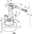
In der
Der Manipulator 12 weist insgesamt 6 rotatorische Bewegungsachsen 13 - 18 auf, die durch als Elektromotoren ausgebildete Aktoren 33 - 38 angetrieben werden. Den Aktoren 33 - 38 sind jeweils in
Die Achsensensoren 43 - 48 können als separate Drehmoment-Kraftsensoren ausgebildet sein. Es ist alternativ auch möglich, dass das übertragene Drehmoment bzw. die übertragene Kraft aus dem jeweiligen Motorstrom des betreffenden Elektromotor-Aktors 33 - 38 hergeleitet wird und daraus das betreffende Bewegungsachsen- Drehmoment errechnet wird. Zusätzlich sind als Achsensensoren 73 - 78 Positionssensoren vorgesehen, mit denen die rotatorische Position der betreffenden Bewegungsachse 13 - 18 bestimmt wird. Alternativ kann diese Position aus der Anzahl an Motorumdrehungen der betreffenden Aktoren- Motoren hergeleitet werdenThe axis sensors 43 - 48 can be designed as separate torque force sensors. Alternatively, it is also possible for the transmitted torque or the transmitted force to be derived from the respective motor current of the relevant electric motor actuator 33 - 38 and the relevant movement axis torque to be calculated from this. In addition, position sensors are provided as axis sensors 73 - 78, with which the rotary position of the relevant movement axis 13 - 18 is determined. Alternatively, this position can be derived from the number of motor revolutions of the relevant actuator motors.
In der Roboterbasis 20 sind drei als Kraftsensoren ausgebildete Redundanzsensoren 22, 23, 24 angeordnet, die gemeinsam eine Redundanz-Sensoranordnung 26 bilden. Die drei Redundanzsensoren 22 - 24 sind als eindimensionale Kraftsensoren ausgebildet und kartesisch, also rechtwinklig zueinander angeordnet. Die Roboterbasis 20 kann beispielsweise aus zwei übereinanderliegenden Scheiben bestehen, die ausschließlich über sehr steife Federkörper miteinander verbunden sind, wobei zwischen den beiden Scheiben die als hochpräzise Wegsensoren ausgebildeten Redundanzsensoren 22 - 24 angeordnet sind.Three
Die Redundanzsensoren 22 - 24 sind über eine separate Redundanzleitung 25 mit einer Robotersteuerung 60 verbunden. Ebenso sind die Achsensensoren 43 - 48, 73 - 78 mit der Robotersteuerung 60 über eigene Datenleitungen verbunden. Die Messwerte der Achsensensoren 43 - 48, 73 - 78 und der Redundanzsensoren 22 - 24 laufen in einem Redundanz-Modul 62 in der Robotersteuerung 60 zusammen.The redundancy sensors 22 - 24 are connected to a
Das Redundanzmodul 62 ermittelt beispielsweise aus den Redundanz-Manipulatorwerten der Redundanzsensoren 22 - 24 und den Achsenwerten der Achsensensoren 43 - 48, 73 - 78 sowie gegebenenfalls weiteren Sensorwerten und Informationen aus einem Modellspeicher 64 Redundanz-Achsenwerte, die dann in dem Redundanzmodul 62 mit den Achsenwerten verglichen bzw. abgeglichen werden. Schließlich wird über die Ausgabeleitung 66 ein entsprechendes Signal in Abhängigkeit von dem zuvor ausgeführten Abgleich bzw. Vergleich ausgegeben.The
Bei weitgehender Übereinstimmung der Redundanz-Achsenwerte mit den Achsensensor-Achsenwerten wird ein Übereinstimmungssignal über die Ausgabeleitung 66 ausgegeben. Bei nicht ausreichender Übereinstimmung wird durch das Redundanzmodul 62 über die Ausgabeleitung 66 ein Fehlersignal ausgegeben und werden hierdurch geeignete Aktionen ausgelöst, beispielsweise eine Sicherheitsschaltung angesteuert. Bei Feststellung einer unzulässigen Abweichung einer Bewegungsachse kann auf einen Sensorfehler eines Achsensensors oder eines oder mehrerer Redundanzsensoren geschlossen werden.If the redundancy axis values largely match the axis sensor axis values, a match signal is output via the
Voraussetzung für das zuvor beschriebene Verfahren ist, dass die Robotersteuerung 60 über genaue und sichere Informationen über die Physik des Manipulators verfügt, die in dem Modellspeicher 64 abgespeichert ist. Im einzelnen sind dies Informationen über die Massen und Massenschwerpunkte der Manipulator-Armsegmente, die Lage der Bewegungsachsen etc. Auf Basis dieser Informationen können aus allen ermittelten Messwerten der Sensoren Redundanz-Informationen gewonnen werden.The prerequisite for the method described above is that the
Alternativ zu dem zuvor beschriebenen Verfahren können aus den Achsensensor-Achsenwerten auch die entsprechenden Soll-Manipulatorwerte errechnet werden, die dann unmittelbar mit den gemessenen Redundanz-Manipulatorwerten verglichen werden.As an alternative to the method described above, the corresponding target manipulator values can also be calculated from the axis sensor axis values, which are then directly compared with the measured redundancy manipulator values.
In dem Modellspeicher 64 können alternativ auch durch sogenannte Einlernfahrten ermittelte Soll-Werte für alle Sensoren und Bewegungsphasen bzw. -situationen abgespeichert sein, die stets mit den durch die Sensoren 43 - 48, 73 - 78, 22 - 24 erfassten Werten unmittelbar verglichen bzw. abgeglichen werden können.Alternatively, the
Die Regelung der Manipulator-Bewegungen im Normalbetrieb beruht weiterhin auf den Messwerten, die von den Achsensensoren 43 - 48, 73 - 78 ermittelt werden, da diese Messwerte eine hohe Genauigkeit aufweisen.The control of the manipulator movements in normal operation continues to be based on the measured values determined by the axis sensors 43 - 48, 73 - 78, since these measured values have a high degree of accuracy.
Mit den Redundanzsensoren 22 - 24 bzw. der Redundanz-Sensoranordnung 26 kann unabhängig von der Überprüfung der Achsensensoren auch die absolute Last ermittelt werden, die auf den Manipulator 12 wirkt, so dass hierdurch auf einfache Weise eine Überlasterkennung und damit ein Überlastschutz realisiert werden kann.With the redundancy sensors 22 - 24 or the
Claims (7)
Translated fromGermanPriority Applications (4)
| Application Number | Priority Date | Filing Date | Title |
|---|---|---|---|
| DE102007050232.1ADE102007050232B4 (en) | 2007-10-20 | 2007-10-20 | Handling robot and method for controlling a handling robot |
| PCT/EP2008/064048WO2009050271A1 (en) | 2007-10-20 | 2008-10-17 | Manipulator, particularly industrial robot, having a redundant sensor arrangement, and method for the control thereof |
| US12/738,765US8594847B2 (en) | 2007-10-20 | 2008-10-17 | Manipulator, particularly industrial robot, having a redundant sensor arrangement, and method for the control thereof |
| EP08838744AEP2205409B1 (en) | 2007-10-20 | 2008-10-17 | Manipulator, particularly industrial robot, having a redundant sensor arrangement, and method for the control thereof |
Applications Claiming Priority (1)
| Application Number | Priority Date | Filing Date | Title |
|---|---|---|---|
| DE102007050232.1ADE102007050232B4 (en) | 2007-10-20 | 2007-10-20 | Handling robot and method for controlling a handling robot |
Publications (2)
| Publication Number | Publication Date |
|---|---|
| DE102007050232A1 DE102007050232A1 (en) | 2009-04-23 |
| DE102007050232B4true DE102007050232B4 (en) | 2024-05-02 |
Family
ID=40227911
Family Applications (1)
| Application Number | Title | Priority Date | Filing Date |
|---|---|---|---|
| DE102007050232.1AActiveDE102007050232B4 (en) | 2007-10-20 | 2007-10-20 | Handling robot and method for controlling a handling robot |
Country Status (4)
| Country | Link |
|---|---|
| US (1) | US8594847B2 (en) |
| EP (1) | EP2205409B1 (en) |
| DE (1) | DE102007050232B4 (en) |
| WO (1) | WO2009050271A1 (en) |
Cited By (1)
| Publication number | Priority date | Publication date | Assignee | Title |
|---|---|---|---|---|
| US20240190595A1 (en)* | 2022-12-08 | 2024-06-13 | as Strömungstechnik GmbH | Dispensing System and Method of Operating a Dispensing System |
Families Citing this family (149)
| Publication number | Priority date | Publication date | Assignee | Title |
|---|---|---|---|---|
| DE102009047033A1 (en)* | 2009-11-24 | 2011-05-26 | Robert Bosch Gmbh | System and method for collision detection in production or assembly machines |
| DE102010044644B4 (en) | 2010-09-07 | 2018-12-27 | Robert Bosch Gmbh | Method for collision detection for a drive unit |
| US11871901B2 (en) | 2012-05-20 | 2024-01-16 | Cilag Gmbh International | Method for situational awareness for surgical network or surgical network connected device capable of adjusting function based on a sensed situation or usage |
| DE102013010290A1 (en)* | 2013-06-19 | 2014-12-24 | Kuka Laboratories Gmbh | Monitoring a kinematic redundant robot |
| DE202013105036U1 (en)* | 2013-11-08 | 2015-02-10 | Daimler Ag | detector |
| USD774578S1 (en) | 2014-04-09 | 2016-12-20 | Fanuc Corporation | Industrial robot |
| WO2016049006A1 (en) | 2014-09-22 | 2016-03-31 | Kuka Systems Corporation North America | Robotic apparatus and process for the installation of collars and nuts onto fasteners |
| USD774580S1 (en)* | 2014-09-26 | 2016-12-20 | Fanuc Corporation | Industrial robot |
| USD774579S1 (en)* | 2014-09-26 | 2016-12-20 | Fanuc Corporation | Industrial robot |
| US11504192B2 (en) | 2014-10-30 | 2022-11-22 | Cilag Gmbh International | Method of hub communication with surgical instrument systems |
| DE102014223419A1 (en)* | 2014-11-17 | 2016-05-19 | Krones Aktiengesellschaft | Method and device for handling and / or manipulating articles such as containers or piece goods |
| DE102014225252A1 (en)* | 2014-12-09 | 2016-06-09 | Kuka Systems Gmbh | Method for monitoring at least one industrial robot, industrial robot and system with several industrial robots |
| USD768219S1 (en)* | 2014-12-17 | 2016-10-04 | Aktormed Gmbh | Robot system for medical surgeries |
| DE102014119654A1 (en) | 2014-12-29 | 2016-06-30 | Brötje-Automation GmbH | Method for compensating for a deviation of a working point |
| US10201901B2 (en)* | 2015-01-29 | 2019-02-12 | Canon Kabushiki Kaisha | Robot apparatus, method for controlling robot, program, and recording medium |
| DE102015001741A1 (en) | 2015-02-11 | 2016-08-11 | Kuka Roboter Gmbh | Method and system for operating a multi-axis machine, in particular a robot |
| US9897507B2 (en)* | 2015-04-17 | 2018-02-20 | Raytheon Company | Automated work piece center of mass identification system and method for same |
| USD825066S1 (en)* | 2015-08-03 | 2018-08-07 | Imperial Innovations Limited | Surgical arm |
| US10350766B2 (en)* | 2015-09-21 | 2019-07-16 | GM Global Technology Operations LLC | Extended-reach assist device for performing assembly tasks |
| DE102015119424A1 (en) | 2015-11-11 | 2017-05-11 | Reis Gmbh & Co. Kg Maschinenfabrik | Method for processing at least one workpiece |
| DE102016212407A1 (en) | 2016-07-07 | 2018-01-11 | Kuka Systems Gmbh | Sensor plate for attachment to a manipulator |
| US10369702B2 (en) | 2016-10-17 | 2019-08-06 | Raytheon Company | Automated work piece moment of inertia (MOI) identification system and method for same |
| US10828767B2 (en) | 2016-11-11 | 2020-11-10 | Sarcos Corp. | Tunable actuator joint modules having energy recovering quasi-passive elastic actuators with internal valve arrangements |
| US10821614B2 (en) | 2016-11-11 | 2020-11-03 | Sarcos Corp. | Clutched joint modules having a quasi-passive elastic actuator for a robotic assembly |
| US11291510B2 (en) | 2017-10-30 | 2022-04-05 | Cilag Gmbh International | Method of hub communication with surgical instrument systems |
| US11911045B2 (en) | 2017-10-30 | 2024-02-27 | Cllag GmbH International | Method for operating a powered articulating multi-clip applier |
| US11311342B2 (en) | 2017-10-30 | 2022-04-26 | Cilag Gmbh International | Method for communicating with surgical instrument systems |
| US11317919B2 (en) | 2017-10-30 | 2022-05-03 | Cilag Gmbh International | Clip applier comprising a clip crimping system |
| US11510741B2 (en) | 2017-10-30 | 2022-11-29 | Cilag Gmbh International | Method for producing a surgical instrument comprising a smart electrical system |
| US11229436B2 (en) | 2017-10-30 | 2022-01-25 | Cilag Gmbh International | Surgical system comprising a surgical tool and a surgical hub |
| US11026687B2 (en) | 2017-10-30 | 2021-06-08 | Cilag Gmbh International | Clip applier comprising clip advancing systems |
| US11925373B2 (en) | 2017-10-30 | 2024-03-12 | Cilag Gmbh International | Surgical suturing instrument comprising a non-circular needle |
| US11801098B2 (en) | 2017-10-30 | 2023-10-31 | Cilag Gmbh International | Method of hub communication with surgical instrument systems |
| US11564756B2 (en) | 2017-10-30 | 2023-01-31 | Cilag Gmbh International | Method of hub communication with surgical instrument systems |
| US11132462B2 (en) | 2017-12-28 | 2021-09-28 | Cilag Gmbh International | Data stripping method to interrogate patient records and create anonymized record |
| US11896443B2 (en) | 2017-12-28 | 2024-02-13 | Cilag Gmbh International | Control of a surgical system through a surgical barrier |
| US11464535B2 (en) | 2017-12-28 | 2022-10-11 | Cilag Gmbh International | Detection of end effector emersion in liquid |
| US11284936B2 (en) | 2017-12-28 | 2022-03-29 | Cilag Gmbh International | Surgical instrument having a flexible electrode |
| US11304763B2 (en) | 2017-12-28 | 2022-04-19 | Cilag Gmbh International | Image capturing of the areas outside the abdomen to improve placement and control of a surgical device in use |
| US11234756B2 (en) | 2017-12-28 | 2022-02-01 | Cilag Gmbh International | Powered surgical tool with predefined adjustable control algorithm for controlling end effector parameter |
| US11179175B2 (en) | 2017-12-28 | 2021-11-23 | Cilag Gmbh International | Controlling an ultrasonic surgical instrument according to tissue location |
| US11202570B2 (en) | 2017-12-28 | 2021-12-21 | Cilag Gmbh International | Communication hub and storage device for storing parameters and status of a surgical device to be shared with cloud based analytics systems |
| US11786245B2 (en) | 2017-12-28 | 2023-10-17 | Cilag Gmbh International | Surgical systems with prioritized data transmission capabilities |
| US11076921B2 (en) | 2017-12-28 | 2021-08-03 | Cilag Gmbh International | Adaptive control program updates for surgical hubs |
| US20190201142A1 (en) | 2017-12-28 | 2019-07-04 | Ethicon Llc | Automatic tool adjustments for robot-assisted surgical platforms |
| US11659023B2 (en) | 2017-12-28 | 2023-05-23 | Cilag Gmbh International | Method of hub communication |
| US11376002B2 (en) | 2017-12-28 | 2022-07-05 | Cilag Gmbh International | Surgical instrument cartridge sensor assemblies |
| US11571234B2 (en) | 2017-12-28 | 2023-02-07 | Cilag Gmbh International | Temperature control of ultrasonic end effector and control system therefor |
| US11273001B2 (en) | 2017-12-28 | 2022-03-15 | Cilag Gmbh International | Surgical hub and modular device response adjustment based on situational awareness |
| US11291495B2 (en) | 2017-12-28 | 2022-04-05 | Cilag Gmbh International | Interruption of energy due to inadvertent capacitive coupling |
| US11786251B2 (en) | 2017-12-28 | 2023-10-17 | Cilag Gmbh International | Method for adaptive control schemes for surgical network control and interaction |
| US10892995B2 (en) | 2017-12-28 | 2021-01-12 | Ethicon Llc | Surgical network determination of prioritization of communication, interaction, or processing based on system or device needs |
| US11304745B2 (en) | 2017-12-28 | 2022-04-19 | Cilag Gmbh International | Surgical evacuation sensing and display |
| US11308075B2 (en) | 2017-12-28 | 2022-04-19 | Cilag Gmbh International | Surgical network, instrument, and cloud responses based on validation of received dataset and authentication of its source and integrity |
| US11464559B2 (en) | 2017-12-28 | 2022-10-11 | Cilag Gmbh International | Estimating state of ultrasonic end effector and control system therefor |
| US20190206569A1 (en) | 2017-12-28 | 2019-07-04 | Ethicon Llc | Method of cloud based data analytics for use with the hub |
| US11903601B2 (en) | 2017-12-28 | 2024-02-20 | Cilag Gmbh International | Surgical instrument comprising a plurality of drive systems |
| US11529187B2 (en) | 2017-12-28 | 2022-12-20 | Cilag Gmbh International | Surgical evacuation sensor arrangements |
| US11602393B2 (en) | 2017-12-28 | 2023-03-14 | Cilag Gmbh International | Surgical evacuation sensing and generator control |
| US11304699B2 (en) | 2017-12-28 | 2022-04-19 | Cilag Gmbh International | Method for adaptive control schemes for surgical network control and interaction |
| US11832899B2 (en) | 2017-12-28 | 2023-12-05 | Cilag Gmbh International | Surgical systems with autonomously adjustable control programs |
| US11013563B2 (en) | 2017-12-28 | 2021-05-25 | Ethicon Llc | Drive arrangements for robot-assisted surgical platforms |
| US11540855B2 (en) | 2017-12-28 | 2023-01-03 | Cilag Gmbh International | Controlling activation of an ultrasonic surgical instrument according to the presence of tissue |
| US11026751B2 (en) | 2017-12-28 | 2021-06-08 | Cilag Gmbh International | Display of alignment of staple cartridge to prior linear staple line |
| US11559308B2 (en) | 2017-12-28 | 2023-01-24 | Cilag Gmbh International | Method for smart energy device infrastructure |
| US12396806B2 (en) | 2017-12-28 | 2025-08-26 | Cilag Gmbh International | Adjustment of a surgical device function based on situational awareness |
| US11389164B2 (en) | 2017-12-28 | 2022-07-19 | Cilag Gmbh International | Method of using reinforced flexible circuits with multiple sensors to optimize performance of radio frequency devices |
| US11832840B2 (en) | 2017-12-28 | 2023-12-05 | Cilag Gmbh International | Surgical instrument having a flexible circuit |
| US11666331B2 (en) | 2017-12-28 | 2023-06-06 | Cilag Gmbh International | Systems for detecting proximity of surgical end effector to cancerous tissue |
| US11253315B2 (en) | 2017-12-28 | 2022-02-22 | Cilag Gmbh International | Increasing radio frequency to create pad-less monopolar loop |
| US12376855B2 (en) | 2017-12-28 | 2025-08-05 | Cilag Gmbh International | Safety systems for smart powered surgical stapling |
| US11744604B2 (en) | 2017-12-28 | 2023-09-05 | Cilag Gmbh International | Surgical instrument with a hardware-only control circuit |
| US11896322B2 (en) | 2017-12-28 | 2024-02-13 | Cilag Gmbh International | Sensing the patient position and contact utilizing the mono-polar return pad electrode to provide situational awareness to the hub |
| US20190201112A1 (en) | 2017-12-28 | 2019-07-04 | Ethicon Llc | Computer implemented interactive surgical systems |
| US12127729B2 (en) | 2017-12-28 | 2024-10-29 | Cilag Gmbh International | Method for smoke evacuation for surgical hub |
| US12062442B2 (en) | 2017-12-28 | 2024-08-13 | Cilag Gmbh International | Method for operating surgical instrument systems |
| US11419630B2 (en) | 2017-12-28 | 2022-08-23 | Cilag Gmbh International | Surgical system distributed processing |
| US11266468B2 (en) | 2017-12-28 | 2022-03-08 | Cilag Gmbh International | Cooperative utilization of data derived from secondary sources by intelligent surgical hubs |
| US11969216B2 (en) | 2017-12-28 | 2024-04-30 | Cilag Gmbh International | Surgical network recommendations from real time analysis of procedure variables against a baseline highlighting differences from the optimal solution |
| US12096916B2 (en) | 2017-12-28 | 2024-09-24 | Cilag Gmbh International | Method of sensing particulate from smoke evacuated from a patient, adjusting the pump speed based on the sensed information, and communicating the functional parameters of the system to the hub |
| US11424027B2 (en) | 2017-12-28 | 2022-08-23 | Cilag Gmbh International | Method for operating surgical instrument systems |
| US11937769B2 (en) | 2017-12-28 | 2024-03-26 | Cilag Gmbh International | Method of hub communication, processing, storage and display |
| US11324557B2 (en) | 2017-12-28 | 2022-05-10 | Cilag Gmbh International | Surgical instrument with a sensing array |
| WO2019133144A1 (en) | 2017-12-28 | 2019-07-04 | Ethicon Llc | Detection and escalation of security responses of surgical instruments to increasing severity threats |
| US11998193B2 (en) | 2017-12-28 | 2024-06-04 | Cilag Gmbh International | Method for usage of the shroud as an aspect of sensing or controlling a powered surgical device, and a control algorithm to adjust its default operation |
| US11818052B2 (en) | 2017-12-28 | 2023-11-14 | Cilag Gmbh International | Surgical network determination of prioritization of communication, interaction, or processing based on system or device needs |
| US10918310B2 (en) | 2018-01-03 | 2021-02-16 | Biosense Webster (Israel) Ltd. | Fast anatomical mapping (FAM) using volume filling |
| US11559307B2 (en) | 2017-12-28 | 2023-01-24 | Cilag Gmbh International | Method of robotic hub communication, detection, and control |
| US11166772B2 (en) | 2017-12-28 | 2021-11-09 | Cilag Gmbh International | Surgical hub coordination of control and communication of operating room devices |
| US20190201039A1 (en) | 2017-12-28 | 2019-07-04 | Ethicon Llc | Situational awareness of electrosurgical systems |
| US11576677B2 (en) | 2017-12-28 | 2023-02-14 | Cilag Gmbh International | Method of hub communication, processing, display, and cloud analytics |
| US11317937B2 (en) | 2018-03-08 | 2022-05-03 | Cilag Gmbh International | Determining the state of an ultrasonic end effector |
| US11696760B2 (en) | 2017-12-28 | 2023-07-11 | Cilag Gmbh International | Safety systems for smart powered surgical stapling |
| US11423007B2 (en) | 2017-12-28 | 2022-08-23 | Cilag Gmbh International | Adjustment of device control programs based on stratified contextual data in addition to the data |
| US11589888B2 (en) | 2017-12-28 | 2023-02-28 | Cilag Gmbh International | Method for controlling smart energy devices |
| US11857152B2 (en) | 2017-12-28 | 2024-01-02 | Cilag Gmbh International | Surgical hub spatial awareness to determine devices in operating theater |
| US11678881B2 (en) | 2017-12-28 | 2023-06-20 | Cilag Gmbh International | Spatial awareness of surgical hubs in operating rooms |
| US11633237B2 (en) | 2017-12-28 | 2023-04-25 | Cilag Gmbh International | Usage and technique analysis of surgeon / staff performance against a baseline to optimize device utilization and performance for both current and future procedures |
| US11278281B2 (en) | 2017-12-28 | 2022-03-22 | Cilag Gmbh International | Interactive surgical system |
| US11612444B2 (en) | 2017-12-28 | 2023-03-28 | Cilag Gmbh International | Adjustment of a surgical device function based on situational awareness |
| US11364075B2 (en) | 2017-12-28 | 2022-06-21 | Cilag Gmbh International | Radio frequency energy device for delivering combined electrical signals |
| US11446052B2 (en) | 2017-12-28 | 2022-09-20 | Cilag Gmbh International | Variation of radio frequency and ultrasonic power level in cooperation with varying clamp arm pressure to achieve predefined heat flux or power applied to tissue |
| US11257589B2 (en) | 2017-12-28 | 2022-02-22 | Cilag Gmbh International | Real-time analysis of comprehensive cost of all instrumentation used in surgery utilizing data fluidity to track instruments through stocking and in-house processes |
| US11304720B2 (en) | 2017-12-28 | 2022-04-19 | Cilag Gmbh International | Activation of energy devices |
| US11109866B2 (en) | 2017-12-28 | 2021-09-07 | Cilag Gmbh International | Method for circular stapler control algorithm adjustment based on situational awareness |
| US11969142B2 (en) | 2017-12-28 | 2024-04-30 | Cilag Gmbh International | Method of compressing tissue within a stapling device and simultaneously displaying the location of the tissue within the jaws |
| US11432885B2 (en)* | 2017-12-28 | 2022-09-06 | Cilag Gmbh International | Sensing arrangements for robot-assisted surgical platforms |
| US11311306B2 (en) | 2017-12-28 | 2022-04-26 | Cilag Gmbh International | Surgical systems for detecting end effector tissue distribution irregularities |
| US11419667B2 (en) | 2017-12-28 | 2022-08-23 | Cilag Gmbh International | Ultrasonic energy device which varies pressure applied by clamp arm to provide threshold control pressure at a cut progression location |
| US11410259B2 (en) | 2017-12-28 | 2022-08-09 | Cilag Gmbh International | Adaptive control program updates for surgical devices |
| US11179208B2 (en) | 2017-12-28 | 2021-11-23 | Cilag Gmbh International | Cloud-based medical analytics for security and authentication trends and reactive measures |
| US11864728B2 (en) | 2017-12-28 | 2024-01-09 | Cilag Gmbh International | Characterization of tissue irregularities through the use of mono-chromatic light refractivity |
| US10758310B2 (en) | 2017-12-28 | 2020-09-01 | Ethicon Llc | Wireless pairing of a surgical device with another device within a sterile surgical field based on the usage and situational awareness of devices |
| US20190201090A1 (en) | 2017-12-28 | 2019-07-04 | Ethicon Llc | Capacitive coupled return path pad with separable array elements |
| US11259830B2 (en) | 2018-03-08 | 2022-03-01 | Cilag Gmbh International | Methods for controlling temperature in ultrasonic device |
| US11986233B2 (en) | 2018-03-08 | 2024-05-21 | Cilag Gmbh International | Adjustment of complex impedance to compensate for lost power in an articulating ultrasonic device |
| US11534196B2 (en) | 2018-03-08 | 2022-12-27 | Cilag Gmbh International | Using spectroscopy to determine device use state in combo instrument |
| US12303159B2 (en) | 2018-03-08 | 2025-05-20 | Cilag Gmbh International | Methods for estimating and controlling state of ultrasonic end effector |
| US11213294B2 (en) | 2018-03-28 | 2022-01-04 | Cilag Gmbh International | Surgical instrument comprising co-operating lockout features |
| US11278280B2 (en) | 2018-03-28 | 2022-03-22 | Cilag Gmbh International | Surgical instrument comprising a jaw closure lockout |
| US11589865B2 (en) | 2018-03-28 | 2023-02-28 | Cilag Gmbh International | Methods for controlling a powered surgical stapler that has separate rotary closure and firing systems |
| US11471156B2 (en) | 2018-03-28 | 2022-10-18 | Cilag Gmbh International | Surgical stapling devices with improved rotary driven closure systems |
| US11219453B2 (en) | 2018-03-28 | 2022-01-11 | Cilag Gmbh International | Surgical stapling devices with cartridge compatible closure and firing lockout arrangements |
| US11090047B2 (en) | 2018-03-28 | 2021-08-17 | Cilag Gmbh International | Surgical instrument comprising an adaptive control system |
| US11027435B2 (en) | 2018-12-04 | 2021-06-08 | Raytheon Company | Automated work piece testing system and method for same |
| US11198227B2 (en) | 2018-12-04 | 2021-12-14 | Raytheon Company | Adjustable ballast system and method for same |
| US11241801B2 (en) | 2018-12-31 | 2022-02-08 | Sarcos Corp. | Robotic end effector with dorsally supported actuation mechanism |
| US11357503B2 (en) | 2019-02-19 | 2022-06-14 | Cilag Gmbh International | Staple cartridge retainers with frangible retention features and methods of using same |
| US11464511B2 (en) | 2019-02-19 | 2022-10-11 | Cilag Gmbh International | Surgical staple cartridges with movable authentication key arrangements |
| US11331100B2 (en) | 2019-02-19 | 2022-05-17 | Cilag Gmbh International | Staple cartridge retainer system with authentication keys |
| US11317915B2 (en) | 2019-02-19 | 2022-05-03 | Cilag Gmbh International | Universal cartridge based key feature that unlocks multiple lockout arrangements in different surgical staplers |
| US11369377B2 (en) | 2019-02-19 | 2022-06-28 | Cilag Gmbh International | Surgical stapling assembly with cartridge based retainer configured to unlock a firing lockout |
| JP7057316B2 (en) | 2019-04-26 | 2022-04-19 | ファナック株式会社 | robot |
| DE102019111168B3 (en) | 2019-04-30 | 2020-08-06 | Franka Emika Gmbh | Force that can be generated depending on the measuring range of a torque sensor of a robot manipulator |
| USD950728S1 (en) | 2019-06-25 | 2022-05-03 | Cilag Gmbh International | Surgical staple cartridge |
| USD952144S1 (en) | 2019-06-25 | 2022-05-17 | Cilag Gmbh International | Surgical staple cartridge retainer with firing system authentication key |
| USD964564S1 (en) | 2019-06-25 | 2022-09-20 | Cilag Gmbh International | Surgical staple cartridge retainer with a closure system authentication key |
| DE102020120301A1 (en)* | 2020-07-31 | 2022-02-03 | Bayerische Motoren Werke Aktiengesellschaft | Driving assistance system and driving assistance method for a vehicle |
| US11833676B2 (en) | 2020-12-07 | 2023-12-05 | Sarcos Corp. | Combining sensor output data to prevent unsafe operation of an exoskeleton |
| US20220176559A1 (en)* | 2020-12-07 | 2022-06-09 | Sarcos Corp. | Method for Redundant Control Policies for Safe Operation of an Exoskeleton |
| US20220176558A1 (en)* | 2020-12-07 | 2022-06-09 | Sarcos Corp. | Redundant Control Policies for Safe Operation of an Exoskeleton |
| WO2023099794A1 (en)* | 2021-11-30 | 2023-06-08 | Desarrollo De Máquinas Y Soluciones Automáticas S.L. (Desmasa) | Mechanical grapple for high-pressure processing containers and method for handling high-pressure processing containers using said mechanical grapple |
| CN114454217B (en)* | 2021-12-07 | 2024-06-04 | 苏州艾利特机器人有限公司 | Redundant sensing multidimensional force sensor and force control robot |
| US11826907B1 (en) | 2022-08-17 | 2023-11-28 | Sarcos Corp. | Robotic joint system with length adapter |
| US11717956B1 (en) | 2022-08-29 | 2023-08-08 | Sarcos Corp. | Robotic joint system with integrated safety |
| WO2024098070A1 (en) | 2022-11-04 | 2024-05-10 | Sarcos Corp. | Robotic end-effector having dynamic stiffening elements with resilient spacers for conforming object interaction |
| US11897132B1 (en) | 2022-11-17 | 2024-02-13 | Sarcos Corp. | Systems and methods for redundant network communication in a robot |
| US11924023B1 (en) | 2022-11-17 | 2024-03-05 | Sarcos Corp. | Systems and methods for redundant network communication in a robot |
| DE102023211163A1 (en)* | 2023-11-10 | 2025-05-15 | Bizlink Industry Germany Gmbh | Articulated arm robot and method for monitoring an articulated arm robot |
Citations (6)
| Publication number | Priority date | Publication date | Assignee | Title |
|---|---|---|---|---|
| DE3902247A1 (en) | 1989-01-26 | 1990-08-09 | Bodenseewerk Geraetetech | Device for controlling the movement sequences of handling systems or robots |
| US5339014A (en) | 1990-07-12 | 1994-08-16 | Elge Elektronik-Geratewerk Gmbh & Co. | Apparatus for safety monitoring in protective arrangements with normal and enhanced safety of machinery performing multiple-axis rotations |
| DE4330823A1 (en) | 1993-09-13 | 1995-03-16 | Bosch Gmbh Robert | Drive device with a safety device for special operation |
| DE10162412A1 (en) | 2001-12-19 | 2003-07-10 | Kuka Roboter Gmbh | Device and method for securing devices with freely movable parts |
| DE60010649T2 (en) | 1999-01-19 | 2005-05-19 | Abb Ab | Device for monitoring the operation of a drive arrangement |
| DE102006022889A1 (en) | 2006-05-15 | 2007-11-22 | Kuka Roboter Gmbh | articulated robot |
Family Cites Families (9)
| Publication number | Priority date | Publication date | Assignee | Title |
|---|---|---|---|---|
| US5086401A (en)* | 1990-05-11 | 1992-02-04 | International Business Machines Corporation | Image-directed robotic system for precise robotic surgery including redundant consistency checking |
| ATE318422T1 (en) | 1998-09-09 | 2006-03-15 | Kuka Roboter Gmbh | METHOD AND DEVICE FOR IMPROVING THE DYNAMIC BEHAVIOR OF A ROBOT |
| WO2004103651A1 (en)* | 1999-06-01 | 2004-12-02 | Hirohiko Arai | Control method for cooperative object-carrying robot and device therefor |
| US8010180B2 (en)* | 2002-03-06 | 2011-08-30 | Mako Surgical Corp. | Haptic guidance system and method |
| TW200304608A (en)* | 2002-03-06 | 2003-10-01 | Z Kat Inc | System and method for using a haptic device in combination with a computer-assisted surgery system |
| DE10304019A1 (en) | 2003-02-01 | 2004-11-04 | Kuka Roboter Gmbh | Method for monitoring a machine and such a machine, in particular a robot |
| DE102004026185A1 (en) | 2004-05-28 | 2005-12-22 | Kuka Roboter Gmbh | Method and apparatus for operating a machine, such as a multi-axis industrial robot |
| JP4999012B2 (en)* | 2005-06-06 | 2012-08-15 | インチュイティブ サージカル,インコーポレイテッド | Laparoscopic ultrasonic robotic surgical system |
| DE102005054575B3 (en)* | 2005-11-16 | 2007-04-26 | Deutsches Zentrum für Luft- und Raumfahrt e.V. | Robot arm regulating method, for medical engineering, involves utilizing redundancy of hinges to optimize quality factor to adjust hinges at angle that is perpendicular to instrument axis, where force caused by regulating hinges is zero |
- 2007
- 2007-10-20DEDE102007050232.1Apatent/DE102007050232B4/enactiveActive
- 2008
- 2008-10-17EPEP08838744Apatent/EP2205409B1/enactiveActive
- 2008-10-17WOPCT/EP2008/064048patent/WO2009050271A1/enactiveApplication Filing
- 2008-10-17USUS12/738,765patent/US8594847B2/enactiveActive
Patent Citations (6)
| Publication number | Priority date | Publication date | Assignee | Title |
|---|---|---|---|---|
| DE3902247A1 (en) | 1989-01-26 | 1990-08-09 | Bodenseewerk Geraetetech | Device for controlling the movement sequences of handling systems or robots |
| US5339014A (en) | 1990-07-12 | 1994-08-16 | Elge Elektronik-Geratewerk Gmbh & Co. | Apparatus for safety monitoring in protective arrangements with normal and enhanced safety of machinery performing multiple-axis rotations |
| DE4330823A1 (en) | 1993-09-13 | 1995-03-16 | Bosch Gmbh Robert | Drive device with a safety device for special operation |
| DE60010649T2 (en) | 1999-01-19 | 2005-05-19 | Abb Ab | Device for monitoring the operation of a drive arrangement |
| DE10162412A1 (en) | 2001-12-19 | 2003-07-10 | Kuka Roboter Gmbh | Device and method for securing devices with freely movable parts |
| DE102006022889A1 (en) | 2006-05-15 | 2007-11-22 | Kuka Roboter Gmbh | articulated robot |
Cited By (1)
| Publication number | Priority date | Publication date | Assignee | Title |
|---|---|---|---|---|
| US20240190595A1 (en)* | 2022-12-08 | 2024-06-13 | as Strömungstechnik GmbH | Dispensing System and Method of Operating a Dispensing System |
Also Published As
| Publication number | Publication date |
|---|---|
| WO2009050271A1 (en) | 2009-04-23 |
| US8594847B2 (en) | 2013-11-26 |
| US20100234996A1 (en) | 2010-09-16 |
| EP2205409B1 (en) | 2012-05-30 |
| DE102007050232A1 (en) | 2009-04-23 |
| EP2205409A1 (en) | 2010-07-14 |
Similar Documents
| Publication | Publication Date | Title |
|---|---|---|
| DE102007050232B4 (en) | Handling robot and method for controlling a handling robot | |
| EP2231369B1 (en) | Robot and method for monitoring the torque on such a robot | |
| DE3810691C2 (en) | ||
| DE102010023736B4 (en) | Robot system with problem detection function | |
| DE102007010067B3 (en) | Singularity-based machine testing and calibration procedure | |
| DE102008062622A1 (en) | Method for command input in controller of manipulator, particularly robot, involves detecting force, which acts on manipulator in specific direction, and comparing detected force with stored forces | |
| WO2010069429A1 (en) | Method and device for inputting commands into a control of a manipulator | |
| DE102018124595A1 (en) | Device for detecting a position and location of a robot end effector | |
| EP4124789B1 (en) | Securing of a movable part of a machine | |
| DE102019122416B4 (en) | robot | |
| EP3037219B1 (en) | Secure robot with path progress variables | |
| DE102010048369A1 (en) | Method for safely monitoring manipulator of industrial robot, involves monitoring different security functionalities of robot in between the two states of machine | |
| DE102007059481A1 (en) | Method and device for range monitoring of a manipulator | |
| DE102019134488B4 (en) | industrial robot system | |
| DE102018112370A1 (en) | Direction-dependent collision detection for a robot manipulator | |
| DE102020126209A1 (en) | ROBOT | |
| DE102020206568B4 (en) | Programming system for manually programming a movement of an industrial robot, industrial robot with such a programming system and method for manually programming a movement of an industrial robot | |
| EP2082852B1 (en) | Method and device for monitoring a manipulator | |
| WO2017080649A2 (en) | Sensitive robots using sensor technology arranged before the first robot axis | |
| DE102016013083B4 (en) | Calibrate a model of a process robot and operate a process robot | |
| EP4008497A1 (en) | Validation of a pose of a robot | |
| WO2020161037A1 (en) | Combining two individual robot manipulators to form a robot system by means of calibration | |
| DE102013007742B4 (en) | Method and device for restoring the operational readiness of a multi-axis movement device | |
| DE102012208252A1 (en) | Method for performing highly accurate positioning of guide tool of robot, involves calculating deviation between desired and actual positions of guide tools of robot arms using virtual mechanical model of plant including robots | |
| DE102020203671B4 (en) | Method for controlling a robot arm |
Legal Events
| Date | Code | Title | Description |
|---|---|---|---|
| OP8 | Request for examination as to paragraph 44 patent law | ||
| R081 | Change of applicant/patentee | Owner name:KUKA ROBOTER GMBH, DE Free format text:FORMER OWNERS: DEUTSCHES ZENTRUM FUER LUFT- UND RAUMFAHRT E.V., 51147 KOELN, DE; KUKA ROBOTER GMBH, 86165 AUGSBURG, DE Effective date:20110428 Owner name:DEUTSCHES ZENTRUM FUER LUFT- UND RAUMFAHRT E.V, DE Free format text:FORMER OWNERS: DEUTSCHES ZENTRUM FUER LUFT- UND RAUMFAHRT E.V., 51147 KOELN, DE; KUKA ROBOTER GMBH, 86165 AUGSBURG, DE Effective date:20110428 Owner name:KUKA ROBOTER GMBH, DE Free format text:FORMER OWNER: DEUTSCHES ZENTRUM FUER LUFT- UND, KUKA ROBOTER GMBH, , DE Effective date:20110428 Owner name:KUKA LABORATORIES GMBH, DE Free format text:FORMER OWNER: DEUTSCHES ZENTRUM FUER LUFT- UND, KUKA ROBOTER GMBH, , DE Effective date:20110428 Owner name:DEUTSCHES ZENTRUM FUER LUFT- UND RAUMFAHRT E.V, DE Free format text:FORMER OWNER: DEUTSCHES ZENTRUM FUER LUFT- UND, KUKA ROBOTER GMBH, , DE Effective date:20110428 | |
| R016 | Response to examination communication | ||
| R081 | Change of applicant/patentee | Owner name:DEUTSCHES ZENTRUM FUER LUFT- UND RAUMFAHRT E.V, DE Free format text:FORMER OWNERS: DEUTSCHES ZENTRUM FUER LUFT- UND RAUMFAHRT E.V., 51147 KOELN, DE; KUKA LABORATORIES GMBH, 86165 AUGSBURG, DE Owner name:KUKA ROBOTER GMBH, DE Free format text:FORMER OWNERS: DEUTSCHES ZENTRUM FUER LUFT- UND RAUMFAHRT E.V., 51147 KOELN, DE; KUKA LABORATORIES GMBH, 86165 AUGSBURG, DE Owner name:KUKA ROBOTER GMBH, DE Free format text:FORMER OWNER: DEUTSCHES ZENTRUM FUER LUFT- UND, KUKA LABORATORIES GMBH, , DE Owner name:DEUTSCHES ZENTRUM FUER LUFT- UND RAUMFAHRT E.V, DE Free format text:FORMER OWNER: DEUTSCHES ZENTRUM FUER LUFT- UND, KUKA LABORATORIES GMBH, , DE | |
| R082 | Change of representative | Representative=s name:DOMPATENT VON KREISLER SELTING WERNER - PARTNE, DE Representative=s name:VON KREISLER SELTING WERNER - PARTNERSCHAFT VO, DE | |
| R018 | Grant decision by examination section/examining division | ||
| R119 | Application deemed withdrawn, or ip right lapsed, due to non-payment of renewal fee | ||
| R020 | Patent grant now final |