DE102007030086B4 - Sensor device for driving a door or a window - Google Patents
Sensor device for driving a door or a windowDownload PDFInfo
- Publication number
- DE102007030086B4 DE102007030086B4DE200710030086DE102007030086ADE102007030086B4DE 102007030086 B4DE102007030086 B4DE 102007030086B4DE 200710030086DE200710030086DE 200710030086DE 102007030086 ADE102007030086 ADE 102007030086ADE 102007030086 B4DE102007030086 B4DE 102007030086B4
- Authority
- DE
- Germany
- Prior art keywords
- sensor
- pivot bearing
- bearing
- drive
- sensor device
- Prior art date
- Legal status (The legal status is an assumption and is not a legal conclusion. Google has not performed a legal analysis and makes no representation as to the accuracy of the status listed.)
- Withdrawn - After Issue
Links
- 230000033001locomotionEffects0.000claimsabstractdescription12
- 230000005855radiationEffects0.000description2
- 238000001514detection methodMethods0.000description1
- 238000001125extrusionMethods0.000description1
- 238000003780insertionMethods0.000description1
- 230000037431insertionEffects0.000description1
- 230000008054signal transmissionEffects0.000description1
- 230000001960triggered effectEffects0.000description1
Images
Classifications
- E—FIXED CONSTRUCTIONS
- E05—LOCKS; KEYS; WINDOW OR DOOR FITTINGS; SAFES
- E05F—DEVICES FOR MOVING WINGS INTO OPEN OR CLOSED POSITION; CHECKS FOR WINGS; WING FITTINGS NOT OTHERWISE PROVIDED FOR, CONCERNED WITH THE FUNCTIONING OF THE WING
- E05F15/00—Power-operated mechanisms for wings
- E05F15/60—Power-operated mechanisms for wings using electrical actuators
- E05F15/603—Power-operated mechanisms for wings using electrical actuators using rotary electromotors
- E05F15/611—Power-operated mechanisms for wings using electrical actuators using rotary electromotors for swinging wings
- E05F15/63—Power-operated mechanisms for wings using electrical actuators using rotary electromotors for swinging wings operated by swinging arms
- E—FIXED CONSTRUCTIONS
- E05—LOCKS; KEYS; WINDOW OR DOOR FITTINGS; SAFES
- E05F—DEVICES FOR MOVING WINGS INTO OPEN OR CLOSED POSITION; CHECKS FOR WINGS; WING FITTINGS NOT OTHERWISE PROVIDED FOR, CONCERNED WITH THE FUNCTIONING OF THE WING
- E05F15/00—Power-operated mechanisms for wings
- E05F15/40—Safety devices, e.g. detection of obstructions or end positions
- E05F15/42—Detection using safety edges
- E05F15/43—Detection using safety edges responsive to disruption of energy beams, e.g. light or sound
- E—FIXED CONSTRUCTIONS
- E05—LOCKS; KEYS; WINDOW OR DOOR FITTINGS; SAFES
- E05F—DEVICES FOR MOVING WINGS INTO OPEN OR CLOSED POSITION; CHECKS FOR WINGS; WING FITTINGS NOT OTHERWISE PROVIDED FOR, CONCERNED WITH THE FUNCTIONING OF THE WING
- E05F15/00—Power-operated mechanisms for wings
- E05F15/70—Power-operated mechanisms for wings with automatic actuation
- E05F15/73—Power-operated mechanisms for wings with automatic actuation responsive to movement or presence of persons or objects
- E—FIXED CONSTRUCTIONS
- E05—LOCKS; KEYS; WINDOW OR DOOR FITTINGS; SAFES
- E05F—DEVICES FOR MOVING WINGS INTO OPEN OR CLOSED POSITION; CHECKS FOR WINGS; WING FITTINGS NOT OTHERWISE PROVIDED FOR, CONCERNED WITH THE FUNCTIONING OF THE WING
- E05F15/00—Power-operated mechanisms for wings
- E05F15/40—Safety devices, e.g. detection of obstructions or end positions
- E05F15/42—Detection using safety edges
- E05F15/43—Detection using safety edges responsive to disruption of energy beams, e.g. light or sound
- E05F2015/434—Detection using safety edges responsive to disruption of energy beams, e.g. light or sound with cameras or optical sensors
- E—FIXED CONSTRUCTIONS
- E05—LOCKS; KEYS; WINDOW OR DOOR FITTINGS; SAFES
- E05Y—INDEXING SCHEME ASSOCIATED WITH SUBCLASSES E05D AND E05F, RELATING TO CONSTRUCTION ELEMENTS, ELECTRIC CONTROL, POWER SUPPLY, POWER SIGNAL OR TRANSMISSION, USER INTERFACES, MOUNTING OR COUPLING, DETAILS, ACCESSORIES, AUXILIARY OPERATIONS NOT OTHERWISE PROVIDED FOR, APPLICATION THEREOF
- E05Y2800/00—Details, accessories and auxiliary operations not otherwise provided for
- E05Y2800/20—Combinations of elements
- E05Y2800/21—Combinations of elements of identical elements, e.g. of identical compression springs
- E—FIXED CONSTRUCTIONS
- E05—LOCKS; KEYS; WINDOW OR DOOR FITTINGS; SAFES
- E05Y—INDEXING SCHEME ASSOCIATED WITH SUBCLASSES E05D AND E05F, RELATING TO CONSTRUCTION ELEMENTS, ELECTRIC CONTROL, POWER SUPPLY, POWER SIGNAL OR TRANSMISSION, USER INTERFACES, MOUNTING OR COUPLING, DETAILS, ACCESSORIES, AUXILIARY OPERATIONS NOT OTHERWISE PROVIDED FOR, APPLICATION THEREOF
- E05Y2900/00—Application of doors, windows, wings or fittings thereof
- E05Y2900/10—Application of doors, windows, wings or fittings thereof for buildings or parts thereof
- E05Y2900/13—Type of wing
- E05Y2900/132—Doors
Landscapes
- Power-Operated Mechanisms For Wings (AREA)
Abstract
Translated fromGermanDescription
Translated fromGermanDie Erfindung betrifft eine Sensorvorrichtung für einen Antrieb einer Tür oder eines Fensters nach dem Oberbegriff des Anspruchs 1.The invention relates to a sensor device for driving a door or a window according to the preamble of
Aus der
Diese Anordnung von Antrieb und Sensorleiste ist für eine Montage auf einem Türflügel mit einem schmalen Rahmen nicht geeignet.This arrangement of drive and sensor bar is not suitable for mounting on a door with a narrow frame.
Der Erfindung liegt die Aufgabe zugrunde, eine Anordnung von Antrieb und Sensorleiste zu schaffen, welche zur Anordnung auf schmalen Rahmen von Flügeln geeignet ist und dabei optisch vorteilhaft ist.The invention has for its object to provide an arrangement of drive and sensor bar, which is suitable for placement on narrow frame of wings and is optically advantageous.
Die Aufgabe wird durch die Merkmale des Anspruchs 1 gelöst.The object is solved by the features of
Die Unteransprüche bilden vorteilhafte Ausgestaltungsmöglichkeiten der Erfindung.The subclaims form advantageous embodiments of the invention.
Bei automatischen Drehtüren ist der Flügel der Tür in Bändern schwenkbar gelagert. Bei einer Anordnung des Türantriebs oberhalb des Flügels der Tür kann der Antrieb zum Verschwenken des Flügels über ein Gestänge aus zwei gelenkig miteinander verbundenen Hebeln mit dem Flügel verbunden sein. Dabei ist einer der Hebel drehfest mit einer Abtriebswelle des Antriebs verbunden, während sich der andere Hebel an einem Drehlager auf dem Flügel der Tür abstützt, das am oberen Rand des Flügels festgelegt ist.In automatic hinged doors, the wing of the door is pivotally mounted in bands. In an arrangement of the door drive above the wing of the door, the drive for pivoting the wing via a linkage of two hingedly interconnected levers may be connected to the wing. In this case, one of the levers is rotatably connected to an output shaft of the drive, while the other lever is supported on a pivot bearing on the wing of the door, which is fixed to the upper edge of the wing.
Die Betätigung des Antriebs kann über einen Bewegungsmelder oder einen Tastschalter erfolgen. Zur Absicherung der Bewegung des Flügels sind Sensorleisten vorgesehen, welche die Flügelbewegung anhalten oder reversieren, wenn eine Person oder ein Gegenstand im Schwenkbereich des Flügels erfasst wird. Diese Sensorleisten sind ebenfalls im oberen Bereich des Flügels angeordnet, wodurch insbesondere bei Flügeln, die eine Flügelrahmen – beispielsweise zur Aufnahme eines Türfutters oder einer Verglasung – aufweisen, keine Möglichkeit zur Anordnung des Drehlagers und der Sensorleiste besteht.The actuation of the drive can be done via a motion detector or a push button. To secure the movement of the wing sensor strips are provided which stop or reverse the wing movement when a person or an object is detected in the pivoting range of the wing. These sensor strips are also arranged in the upper region of the wing, which, in particular in the case of wings which have a casement frame, for example for receiving a door lining or a glazing, there is no possibility of arranging the pivot bearing and the sensor strip.
Dieses Problem wird erfindungsgemäß dadurch gelöst, dass die Sensorleiste zur Aufnahme des Drehlagers ausgebildet ist. Dabei kann das Drehlager einteilig oder zweiteilig sein, und es kann in die Sensorleiste einschiebbar oder durch eine Aussparung, die zum Einsetzten einer für die Strahlung der Sensoren durchlässigen Abdeckung vorgesehen ist, in die Sensorleiste einsetzbar sein. Weiterhin kann das Drehlager durch Verschrauben oder durch Klemmung in der Sensorleiste festgelegt werden. In einer weiteren Ausgestaltung kann ein von vorne einsetzbares Drehlager in seiner Außenform zumindest teilweise der Kontur der Abdeckung folgen, wodurch eine optisch homogene Ansicht gebildet wird. Das Drehlager kann auch zum Aufstecken an den seitlichen Enden der Sensorleiste vorgesehen sein.This problem is inventively achieved in that the sensor bar is designed for receiving the pivot bearing. In this case, the rotary bearing can be in one piece or in two parts, and it can be insertable into the sensor strip or insertable into the sensor strip by a recess which is provided for inserting a cover transparent to the radiation of the sensors. Furthermore, the pivot bearing can be determined by screwing or by clamping in the sensor bar. In a further embodiment, a pivot bearing which can be inserted from the front can at least partially follow the contour of the cover in its outer shape, whereby an optically homogeneous view is formed. The pivot bearing can also be provided for attachment to the lateral ends of the sensor bar.
Bei Verwendung eines zweiteiligen, aus einem Lagerbock und einem Lagerzapfen bestehenden Drehlagers, kann das Drehlager alternativ auch mit dem Lagerzapfen in der Sensorleiste festgelegt werden.When using a two-part, consisting of a bearing block and a bearing pivot bearing, the pivot bearing can alternatively be defined with the bearing pin in the sensor bar.
Die erfindungsgemäße Sensorleiste mit integriertem Drehlager ermöglicht insbesondere auch die Anordnung auf Flügeln mit besonders schmalen Flügelrahmen.The sensor strip according to the invention with integrated pivot bearing allows in particular the arrangement on wings with particularly narrow sash.
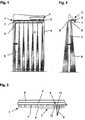
Im Nachfolgenden werden die Ausführungsbeispiele in der Zeichnung anhand der Figuren näher erläutert.In the following, the embodiments are explained in detail in the drawing with reference to FIGS.
Dabei zeigen:Showing:
Die
Am oberen horizontalen Rand des Flügels
In
Es ist in den
Da zur Betätigung des Flügels
Wie es in den
Das Gestänge
Die Sensorleiste
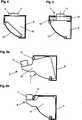
Eine alternative Festlegung des Drehlagers im Profil der Sensorleiste
Ein weiteres Ausführungsbeispiel ist in den
BezugszeichenlisteLIST OF REFERENCE NUMBERS
- 11
- Sensorvorrichtungsensor device
- 22
- Antriebdrive
- 33
- Flügelwing
- 44
- Flügelrahmencasement
- 55
- Gestängelinkage
- 6, 6'6, 6 '
- Sensorleistesensor bar
- 77
- Sensorsensor
- 88th
- Sensorstrahlsensor beam
- 99
- Drehlagerpivot bearing
- 1010
- Lagerbockbearing block
- 1111
- Lagerzapfenpivot
- 1212
- Klemmelementclamping element
- 1313
- Abdeckungcover
Claims (10)
Translated fromGermanPriority Applications (4)
| Application Number | Priority Date | Filing Date | Title |
|---|---|---|---|
| DE200710030086DE102007030086B4 (en) | 2007-06-28 | 2007-06-28 | Sensor device for driving a door or a window |
| DK08158772TDK2009215T3 (en) | 2007-06-28 | 2008-06-23 | Sensor device for a drive at a door or window |
| ES08158772TES2428380T3 (en) | 2007-06-28 | 2008-06-23 | Sensor device of a door or window drive |
| EP20080158772EP2009215B1 (en) | 2007-06-28 | 2008-06-23 | Sensor device for a drive to operate a door or window |
Applications Claiming Priority (1)
| Application Number | Priority Date | Filing Date | Title |
|---|---|---|---|
| DE200710030086DE102007030086B4 (en) | 2007-06-28 | 2007-06-28 | Sensor device for driving a door or a window |
Publications (2)
| Publication Number | Publication Date |
|---|---|
| DE102007030086A1 DE102007030086A1 (en) | 2009-01-02 |
| DE102007030086B4true DE102007030086B4 (en) | 2014-01-30 |
Family
ID=39789973
Family Applications (1)
| Application Number | Title | Priority Date | Filing Date |
|---|---|---|---|
| DE200710030086Withdrawn - After IssueDE102007030086B4 (en) | 2007-06-28 | 2007-06-28 | Sensor device for driving a door or a window |
Country Status (4)
| Country | Link |
|---|---|
| EP (1) | EP2009215B1 (en) |
| DE (1) | DE102007030086B4 (en) |
| DK (1) | DK2009215T3 (en) |
| ES (1) | ES2428380T3 (en) |
Families Citing this family (5)
| Publication number | Priority date | Publication date | Assignee | Title |
|---|---|---|---|---|
| US8225458B1 (en) | 2001-07-13 | 2012-07-24 | Hoffberg Steven M | Intelligent door restraint |
| US9163446B2 (en) | 2010-03-17 | 2015-10-20 | Yale Security Inc. | Door control apparatus |
| KR101951981B1 (en)* | 2015-08-13 | 2019-04-22 | (주)엘지하우시스 | Automatic opening and shutting device for window and smart window using the same |
| US11761253B2 (en) | 2018-04-16 | 2023-09-19 | Assa Abloy Entrance Systems Ab | Finger pinch protection for an entrance system |
| DE102018214215A1 (en)* | 2018-08-22 | 2020-02-27 | Geze Gmbh | Device for monitoring doors, windows or the like |
Citations (3)
| Publication number | Priority date | Publication date | Assignee | Title |
|---|---|---|---|---|
| DE19518397A1 (en)* | 1995-05-19 | 1996-11-21 | Geze Gmbh & Co | Automatic operating mechanism for hinged door |
| DE19630877A1 (en)* | 1996-07-31 | 1998-02-05 | Dorma Gmbh & Co Kg | Slide rail |
| DE10228930A1 (en)* | 2002-06-28 | 2004-01-15 | Geze Gmbh | Sensor device for an automatic swing door system |
Family Cites Families (1)
| Publication number | Priority date | Publication date | Assignee | Title |
|---|---|---|---|---|
| DE4339272A1 (en)* | 1993-11-18 | 1995-05-24 | Geze Gmbh & Co | Automatic door closing mechanism for hinged, manually opened door |
- 2007
- 2007-06-28DEDE200710030086patent/DE102007030086B4/ennot_activeWithdrawn - After Issue
- 2008
- 2008-06-23ESES08158772Tpatent/ES2428380T3/enactiveActive
- 2008-06-23EPEP20080158772patent/EP2009215B1/enactiveActive
- 2008-06-23DKDK08158772Tpatent/DK2009215T3/enactive
Patent Citations (3)
| Publication number | Priority date | Publication date | Assignee | Title |
|---|---|---|---|---|
| DE19518397A1 (en)* | 1995-05-19 | 1996-11-21 | Geze Gmbh & Co | Automatic operating mechanism for hinged door |
| DE19630877A1 (en)* | 1996-07-31 | 1998-02-05 | Dorma Gmbh & Co Kg | Slide rail |
| DE10228930A1 (en)* | 2002-06-28 | 2004-01-15 | Geze Gmbh | Sensor device for an automatic swing door system |
Also Published As
| Publication number | Publication date |
|---|---|
| DE102007030086A1 (en) | 2009-01-02 |
| EP2009215A1 (en) | 2008-12-31 |
| DK2009215T3 (en) | 2013-11-04 |
| EP2009215B1 (en) | 2013-07-31 |
| ES2428380T3 (en) | 2013-11-07 |
Similar Documents
| Publication | Publication Date | Title |
|---|---|---|
| EP1963606B1 (en) | Sliding door | |
| DE102007030086B4 (en) | Sensor device for driving a door or a window | |
| EP1707726B1 (en) | Device for opening and closing a window or door slidably arranged on a frame | |
| EP0531626B1 (en) | Fitting, in particular for tiltable and from one plane to a second parallel plane movable wings | |
| DE20019307U1 (en) | Security cabinet | |
| EP2365176B1 (en) | Device for unlocking a window, flap or similar | |
| DE102012202981B4 (en) | Fitting for a parallel storable and movable in this position the wing of a window, a door or the like | |
| DE10300653A1 (en) | Tilting mechanism for opening window has hinge on bottom edge and stop linkage at top edge or on side edge limiting movement | |
| DE10323704B4 (en) | A drive | |
| EP1813754B1 (en) | Door closer | |
| DE19745180A1 (en) | Lock mechanism for opening or closing window or door | |
| EP2728098B1 (en) | Drive for opening and/or closing a swinging door wing | |
| EP1614844A2 (en) | Pivot device | |
| DE102008015684B4 (en) | Drive for a wing of a window | |
| EP1757765B2 (en) | Fine-framed door | |
| DE19632952C2 (en) | Means for operating the pivotally mounted wing of a shutter or the like | |
| EP2674560A2 (en) | Window or door with drive device | |
| EP1780362B1 (en) | Motor drive for swinging wings | |
| EP1170448A1 (en) | Carriage for a parallel sliding and tiltable fitting of a building window or building door as well as a building window or building door with such a fitting | |
| DE19827813C2 (en) | Door or window hinge | |
| DE102006061857B4 (en) | Finger trap protection for sectional doors or folding doors | |
| DE102016123800A1 (en) | Sliding element | |
| DE9310791U1 (en) | Motorized drive device for a single or multi-leaf door leaf | |
| DE202005009745U1 (en) | fitting assembly | |
| DE102013210272B4 (en) | Closing device of a building opening |
Legal Events
| Date | Code | Title | Description |
|---|---|---|---|
| OP8 | Request for examination as to paragraph 44 patent law | ||
| R016 | Response to examination communication | ||
| R018 | Grant decision by examination section/examining division | ||
| R026 | Opposition filed against patent | ||
| R079 | Amendment of ipc main class | Free format text:PREVIOUS MAIN CLASS: E05F0015200000 Ipc:E05F0015730000 | |
| R026 | Opposition filed against patent | Effective date:20140424 | |
| R079 | Amendment of ipc main class | Free format text:PREVIOUS MAIN CLASS: E05F0015200000 Ipc:E05F0015730000 Effective date:20141217 | |
| R031 | Decision of examining division/federal patent court maintaining patent unamended now final | ||
| R120 | Application withdrawn or ip right abandoned |