DE102007029083B4 - Card carrier with Detektierplättchen - Google Patents
Card carrier with DetektierplättchenDownload PDFInfo
- Publication number
- DE102007029083B4 DE102007029083B4DE102007029083.9ADE102007029083ADE102007029083B4DE 102007029083 B4DE102007029083 B4DE 102007029083B4DE 102007029083 ADE102007029083 ADE 102007029083ADE 102007029083 B4DE102007029083 B4DE 102007029083B4
- Authority
- DE
- Germany
- Prior art keywords
- antenna
- chip
- data carrier
- card data
- detektierplättchen
- Prior art date
- Legal status (The legal status is an assumption and is not a legal conclusion. Google has not performed a legal analysis and makes no representation as to the accuracy of the status listed.)
- Expired - Fee Related
Links
Images

Classifications
- G—PHYSICS
- G06—COMPUTING OR CALCULATING; COUNTING
- G06K—GRAPHICAL DATA READING; PRESENTATION OF DATA; RECORD CARRIERS; HANDLING RECORD CARRIERS
- G06K19/00—Record carriers for use with machines and with at least a part designed to carry digital markings
- G06K19/06—Record carriers for use with machines and with at least a part designed to carry digital markings characterised by the kind of the digital marking, e.g. shape, nature, code
- G06K19/067—Record carriers with conductive marks, printed circuits or semiconductor circuit elements, e.g. credit or identity cards also with resonating or responding marks without active components
- G06K19/07—Record carriers with conductive marks, printed circuits or semiconductor circuit elements, e.g. credit or identity cards also with resonating or responding marks without active components with integrated circuit chips
- G06K19/077—Constructional details, e.g. mounting of circuits in the carrier
- G06K19/07749—Constructional details, e.g. mounting of circuits in the carrier the record carrier being capable of non-contact communication, e.g. constructional details of the antenna of a non-contact smart card
- G06K19/0775—Constructional details, e.g. mounting of circuits in the carrier the record carrier being capable of non-contact communication, e.g. constructional details of the antenna of a non-contact smart card arrangements for connecting the integrated circuit to the antenna
- G06K19/07756—Constructional details, e.g. mounting of circuits in the carrier the record carrier being capable of non-contact communication, e.g. constructional details of the antenna of a non-contact smart card arrangements for connecting the integrated circuit to the antenna the connection being non-galvanic, e.g. capacitive
- H—ELECTRICITY
- H01—ELECTRIC ELEMENTS
- H01Q—ANTENNAS, i.e. RADIO AERIALS
- H01Q1/00—Details of, or arrangements associated with, antennas
- H01Q1/12—Supports; Mounting means
- H01Q1/22—Supports; Mounting means by structural association with other equipment or articles
- H01Q1/2208—Supports; Mounting means by structural association with other equipment or articles associated with components used in interrogation type services, i.e. in systems for information exchange between an interrogator/reader and a tag/transponder, e.g. in Radio Frequency Identification [RFID] systems
- H—ELECTRICITY
- H01—ELECTRIC ELEMENTS
- H01Q—ANTENNAS, i.e. RADIO AERIALS
- H01Q1/00—Details of, or arrangements associated with, antennas
- H01Q1/36—Structural form of radiating elements, e.g. cone, spiral, umbrella; Particular materials used therewith
- H01Q1/38—Structural form of radiating elements, e.g. cone, spiral, umbrella; Particular materials used therewith formed by a conductive layer on an insulating support
- H—ELECTRICITY
- H01—ELECTRIC ELEMENTS
- H01Q—ANTENNAS, i.e. RADIO AERIALS
- H01Q7/00—Loop antennas with a substantially uniform current distribution around the loop and having a directional radiation pattern in a plane perpendicular to the plane of the loop
- H—ELECTRICITY
- H01—ELECTRIC ELEMENTS
- H01Q—ANTENNAS, i.e. RADIO AERIALS
- H01Q9/00—Electrically-short antennas having dimensions not more than twice the operating wavelength and consisting of conductive active radiating elements
- H01Q9/04—Resonant antennas
- H01Q9/0407—Substantially flat resonant element parallel to ground plane, e.g. patch antenna
Landscapes
- Engineering & Computer Science (AREA)
- Microelectronics & Electronic Packaging (AREA)
- Computer Hardware Design (AREA)
- Physics & Mathematics (AREA)
- General Physics & Mathematics (AREA)
- Theoretical Computer Science (AREA)
- Details Of Aerials (AREA)
- Credit Cards Or The Like (AREA)
- Support Of Aerials (AREA)
- Near-Field Transmission Systems (AREA)
Abstract
Translated fromGerman
Description
Translated fromGermanDie Erfindung betrifft einen Kartendatenträger mit einem Detektierplättchen nach dem Oberbegriff des Anspruchs 1.The invention relates to a card data carrier with a detection wafer according to the preamble of claim 1.
Kartendatenträger sind als Ausweis-, Berechtigungs- und Zugangsdatenträger bekannt und umfassen einen oder mehrere Datenspeicher auf einer Kunststoffkarte im Checkkartenformat. Das Checkkartenformat als einheitliche Größe hat sich inzwischen weltweit durchgesetzt, da es manuell gut handhabbar ist, eine visuell sichtbare Wiedergabe wichtiger Informationen erlaubt, einheitlich in sichtbaren Aufbewahrungstaschen am Körper getragen werden kann, wie auch in üblichen Aufbewahrungsfächern in Brieftaschen und Portemonnaies verstaut werden kann.Card media is known as a credential, credential, and credential medium and includes one or more data stores on a plastic card in check card format. The check card format as a uniform size has now become established worldwide, as it is manually manageable, allows a visually visible reproduction of important information, can be worn uniformly in visible storage bags on the body, as well as stowed in ordinary storage compartments in wallets and purses.
Während Datenspeicher bisher als Magnetstreifen und/oder kontaktierte Speicherchips ausgeführt wurden, gibt es inzwischen auch fernlesbare, funkgestützte Detektierplättchen, die ihre Informationen über ein elektromagnetisches Feld übertragen können. Solche Detektierplättchen bestehen aus ein Chip und wenigstens einer Antenne.Whereas data memories have hitherto been embodied as magnetic strips and / or contacted memory chips, there are now also remote-readable, radio-assisted detection plates which can transmit their information via an electromagnetic field. Such Detektierplättchen consist of a chip and at least one antenna.
Funkgestützte Detektierplättchen sind im LF-Bereich, HF-Bereich und UHF-Bereich zugelassen. Wegen des Checkkartenformats lassen sich Antennen für diese Detektierplättchen im LF-Bereich nur als magnetische Antennen und im HF-Bereich wahlweise als magnetische Antennen oder stark verkürzte elektrische Antennen realisieren. Im UHF-Bereich besteht die Möglichkeit, Antennen als magnetische Antennen und/oder nur gering verkürzte elektrische Antennen zu realisieren.Radio-controlled detector plates are approved in the LF range, HF range and UHF range. Because of the check card format, antennas for these detector plates in the LF range can only be realized as magnetic antennas and in the HF range optionally as magnetic antennas or sharply shortened electrical antennas. In the UHF range, it is possible to realize antennas as magnetic antennas and / or only slightly shortened electrical antennas.
Detektierplättchen im UHF-Bereich bieten gegenüber Detektierplättchen in den anderen Frequenzbereichen den Vorteil einer sehr schnellen Datenübertragung, so dass auch bei Anwendung eines Antikollisionsverfahrens zur Unterscheidung mehrerer gleichzeitig im Lesefeld befindlicher Detektierplättchen nur geringe Leseverzögerungen eintreten. Darüber hinaus besteht der Vorteil, wahlweise durch ausschließlichen Einsatz einer magnetischen Antenne die Lesereichweite extrem zu beschränken, bei Einsatz einer elektrischen, nur geringfügig verkürzten oder nicht verkürzten Antenne aber eine im Vergleich zu LF-Detektierplättchen oder HF-Detektierplättchen auf Checkkarten sehr hohe Lesereichweite zu erzielen.Detector platelets in the UHF range offer the advantage of very fast data transmission compared with detector platelets in the other frequency ranges, so that even when using an anti-collision method for distinguishing a plurality of detector platelets simultaneously in the reading field, only slight read delays occur. In addition, there is the advantage of optionally restricting the reading range by the exclusive use of a magnetic antenna when using an electrical, only slightly shortened or not shortened antenna but to achieve a very high reading range compared to LF-Detektierplättchen or RF detection plates on check cards ,
Aus der
Aus Patent Abstracts of Japan:
Außerdem ist aus der gattungsbildenden
Die Polantenne ist kapazitiv mit den Leiterschleifenantennen gekoppelt, wodurch die Antennenfläche der Polantenne vergrößert und als Folge davon auch deren Bandbreite vergrößert wird. Die Polantenne ist stets zusätzlich zu den Leiterschleifenantennen vorhanden. Eine gemeinsame Nutzung ein und derselben Antennenbestandteile für unterschiedliche Frequenzen erfolgt nicht. Vielmehr ist für jede Frequenz eine eigene Antenne vorgesehen.The pole antenna is capacitively coupled to the conductor loop antennas, thereby increasing the antenna surface of the pole antenna and, as a result, increasing its bandwidth. The pole antenna is always present in addition to the conductor loop antennas. A common use of the same antenna components for different frequencies does not occur. Rather, a separate antenna is provided for each frequency.
Aus der
Schließlich ist aus der
Eine ähnliche Anordnung aus zwei magnetisch gekoppelten Schwingkreisen, von denen nur einer mit einer elektronischen Schaltung verbunden ist, ist auch aus der
Der Erfindung liegt die Aufgabe zugrunde, bei funkgestützten Detektierplättchen im HF-Bereich zusätzlich ein Detektierplättchen im UHF-Bereich zu schaffen.The invention is based on the object of additionally providing a detection wafer in the UHF range in the case of radio-assisted detection wafers in the HF range.
Diese Aufgabe wird bei einem Kartendatenträger mit einem Detektierplättchen nach dem Oberbegriff des Anspruchs 1 durch die Merkmale dieses Anspruchs 1 gelöst.This object is achieved in a card data carrier with a detection wafer according to the preamble of claim 1 by the features of this claim 1.
Weiterbildungen und vorteilhafte Ausgestaltungen ergeben sich aus den Unteransprüchen. Further developments and advantageous embodiments will become apparent from the dependent claims.
Der Erfindung liegt die Überlegung zugrunde, dass durch ein Detektierplättchen aus einem Chip und einer magnetischen Antenne die magnetischen Komponenten des elektromagnetischen Wechselfeldes im Nahfeld überwiegen, daher die Ausbreitung des elektromagnetischen Wechselfeldes durch metallische Gegenstände im Nahfeld weniger beeinträchtigt wird, als bei Verwendung einer die elektrischen Komponenten bevorzugt abstrahlenden Antenne und dass als Schutz gegen Ausspähen von gespeicherten Daten des Kartendatenträgers die Lesereichweite begrenzt ist. Ein Einsatz derselben magnetischen Antenne als induktive Koppelschleife bietet aber auch die Möglichkeit, fest oder wahlweise mit einer Verstärkerantenne gekoppelt zu werden, um die Lesereichweite grundsätzlich oder wahlweise erheblich zu steigern.The invention is based on the consideration that the magnetic components of the electromagnetic alternating field predominate in the near field due to a detection wafer made of a chip and a magnetic antenna, therefore the propagation of the electromagnetic alternating field is less affected by metallic objects in the near field than when using one of the electrical components preferably radiating antenna and that as a protection against spying on stored data of the map data carrier, the reading range is limited. However, the use of the same magnetic antenna as an inductive coupling loop also offers the possibility of being permanently or selectively coupled to an amplifier antenna, in order to fundamentally or optionally increase the reading range considerably.
Die Koppelschleife des Detektierplättchens ist mit einer Verstärkerantenne induktiv gekoppelt sein.The coupling loop of the detector wafer is to be inductively coupled to an amplifier antenna.
Über die Kopplung mit einer Verstärkerantenne, die eine rein passiv wirkende Komponente bildet, kann die Lesereichweite des Detektierplättchens wesentlich erhöht werden.By coupling with an amplifier antenna, which forms a purely passive-acting component, the reading range of the detector plate can be significantly increased.
Die Verstärkerantenne ist als elektrische Antenne ausgebildet.The amplifier antenna is designed as an electrical antenna.
Durch eine elektrische Antenne kann über deren Design, insbesondere deren Länge und Form, in einfacher Weise eine exakte Anpassung der Resonanzfrequenz der Antenne an die Arbeitsfrequenz des Detektierplättchens und Lesegeräts vorgenommen werden, so dass die Antenne mit dem maximal möglichen Wirkungsgrad strahlen kann.By means of an electrical antenna, its design, in particular its length and shape, can easily be used to precisely adapt the resonant frequency of the antenna to the operating frequency of the detector plate and reading device, so that the antenna can radiate with the maximum possible efficiency.
Die elektrische Antenne kann in oder auf dem Kartendatenträger selbst angeordnet sein.The electrical antenna can be arranged in or on the card data carrier itself.
Das Detektierplättchen auf dem Kartendatenträger erhält so eine erhöhte Lesereichweite und kann im Fernfeld mit einer magnetischen oder elektrischen Leseantenne gelesen werden. Die Koppelschleife des Detektierplättchens bildet außerdem eine eigenständige magnetische Antenne, die im Nahfeld mit einer magnetischen Leseantenne gelesen werden kann.The detector pad on the card media thus receives an increased reading range and can be read in the far field with a magnetic or electrical reading antenna. The coupling loop of the detector wafer also forms a standalone magnetic antenna that can be read in the near field with a magnetic reading antenna.
Die elektrische Antenne kann Bestandteil einer Antenne eines Detektierplättchens für den HF-Bereich sein.The electrical antenna can be part of an antenna of a detector plate for the HF range.
Dadurch lässt sich ohne Mehraufwand die Lesereichweite eines auf dem Kartenträger angeordneten Detektierplättchens für den UHF-Bereich erhöhen.As a result, the reading range of a detection wafer arranged on the card carrier for the UHF range can be increased without additional expenditure.
Die elektrische Antenne kann auch in oder auf einer Aufbewahrungshülle oder Halterung des Kartendatenträgers angeordnet sein.The electrical antenna can also be arranged in or on a storage case or holder of the card data carrier.
Der Kartendatenträger mit dem Detektierplättchen für sich genommen hat dann nur eine geringe Lesereichweite. Durch Einschieben des Kartendatenträgers in die Aufbewahrungshülle oder Halterung wird die Koppelschleife auf dem Kartendatenträger mit der elektrische Antenne in oder auf der Aufbewahrungshülle oder Halterung gekoppelt und dadurch eine wesentlich erhöhte Lesereichweite erzielt. Gleichzeitig wird der Kartendatenträger dann definiert gehaltert und aufbewahrt und zusätzlich mechanisch geschützt. Durch die definierte Halterung wird auch eine stabile Leseverbindung mit einem Lesegerät gewährleistet, was dann vorteilhaft ist, wenn über die Anwesenheit des Kartendatenträgers Betriebsfunktionen eines Gerätes oder einer Maschine freigeschaltet werden sollen bzw. ein Fahrzeug identifiziert und eine Schranke geöffnet werden soll.The card data carrier with the detector plate taken separately has then only a small reading range. By inserting the card data carrier into the storage case or holder, the coupling loop on the card data carrier is coupled to the electric antenna in or on the storage case or holder, thereby achieving a substantially increased reading range. At the same time, the card data carrier is then defined held and stored and additionally mechanically protected. The defined holder also ensures a stable reading connection with a reading device, which is advantageous when operating functions of a device or a machine are to be enabled via the presence of the card data carrier or a vehicle is to be identified and a barrier is to be opened.
Nachfolgend wird die Erfindung anhand von Ausführungsbeispielen erläutert, die in der Zeichnung dargestellt sind. In der Zeichnung zeigen:
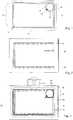
1 einen Kartendatenträger mit zwei Detektierplättchen, von denen eines für den UHF-Bereich bemessen, mittels einer Folie aufgeklebt und seine Koppelschleife mit einer vorhandenen HF-Antenne gekoppelt ist,2 eine Aufbewahrungshülle mit einer elektrischen Antenne,3 eine Aufbewahrungshülle mit einer elektrischen Antenne nach1 und einem in die Aufbewahrungshülle eingeschobenen Kartendatenträger nach1 ,4 einen Kartendatenträger mit zwei Detektierplättchen, von denen eines für den UHF-Bereich bemessen, integral im Karten insert angeordnet und seine Koppelschleife mit einer vorhandenen HF-Antenne gekoppelt ist,5 einen Interposer mit einem Chip und Anschlüssen für eine HF-Antenne.
1 a card carrier with two detector pads, one of which is sized for the UHF range, glued by a foil and its coupling loop coupled to an existing RF antenna,2 a storage case with an electric antenna,3 a storage case with an electric antenna behind1 and a card disk inserted in the storage case1 .4 a card carrier having two detector pads, one of which is sized for the UHF range, integrally disposed in the card insert and its coupling loop coupled to an existing RF antenna,5 an interposer with a chip and connectors for an RF antenna.
Die Koppelschleife
Die Aufbewahrungshülle
Die erfindungsgemäße Ausgestaltung ermöglicht folgende Anwendungen.The embodiment of the invention enables the following applications.
Kartendatenträger mit Detektierplättchen bestehend aus einem Chip und einer mit dem Chip verbundenen Koppelschleife ohne Verstärkerantenne verfügen nur über eine kleine Lesereichweite und deren gespeicherte Daten können daher nicht durch Fernauslesen ausspioniert werden. Die Lesereichweite kann aber in Verbindung mit einer Aufbewahrungshülle und einer auf oder in der Aufbewahrungshülle angeordneten Verstärkerantenne erhöht werden.Card data carrier with Detektierplättchen consisting of a chip and a chip-connected coupling loop without amplifier antenna have only a small reading range and their stored data can therefore not be spied on by remote reading. However, the reading range may be increased in conjunction with a storage case and an amplifier antenna disposed on or in the storage case.
Die Aufbewahrungshülle mit der Verstärkerantenne kann am Einsatzort, z. B. einer Person, einem Gerät, einer Maschine oder einem Fahrzeug verbleiben, um dort mittels des eingesteckten Kartendatenträgers im Fernfeld Betriebsfunktionen freizuschalten und den Kartendatenträger selbst zu haltern und aufzubewahren. Gleichzeitig dient die Aufbewahrungshülle auch als Positionierhilfe für die Kopplung der kartenseitigen Koppelschleife mit der hüllenseitgen Verstärkerantenne.The storage case with the amplifier antenna at the site, z. B. a person, a device, a machine or a vehicle to unlock there by means of the inserted card data carrier in the far field operating functions and to support the card media itself and keep. At the same time the storage case also serves as a positioning aid for the coupling of the card-side coupling loop with the envelope-side amplifier antenna.
Durch die Auslesbarkeit im Fernfeld kann die Aufbewahrungshülle rein passiv gestaltet sein, während eine aktive Leseantenne abgesetzt und so gegen Manipulationen oder Beschädigung weitgehend unzugänglich angeordnet sein kann. Eine sichere Datenübertragung ist dennoch gewährleistet.Due to the readability in the far field, the storage case can be made purely passive, while an active reading antenna can be deposited and so arranged against manipulation or damage largely inaccessible. A secure data transmission is nevertheless guaranteed.
Claims (4)
Translated fromGermanPriority Applications (3)
| Application Number | Priority Date | Filing Date | Title |
|---|---|---|---|
| DE102007029083.9ADE102007029083B4 (en) | 2007-06-21 | 2007-06-21 | Card carrier with Detektierplättchen |
| EP08010245.2AEP2009583B1 (en) | 2007-06-21 | 2008-06-05 | Card data carrier with detection pad |
| US12/214,099US8556182B2 (en) | 2007-06-21 | 2008-06-17 | Card data storage device with detector plate |
Applications Claiming Priority (1)
| Application Number | Priority Date | Filing Date | Title |
|---|---|---|---|
| DE102007029083.9ADE102007029083B4 (en) | 2007-06-21 | 2007-06-21 | Card carrier with Detektierplättchen |
Publications (2)
| Publication Number | Publication Date |
|---|---|
| DE102007029083A1 DE102007029083A1 (en) | 2008-12-24 |
| DE102007029083B4true DE102007029083B4 (en) | 2019-05-16 |
Family
ID=39643917
Family Applications (1)
| Application Number | Title | Priority Date | Filing Date |
|---|---|---|---|
| DE102007029083.9AExpired - Fee RelatedDE102007029083B4 (en) | 2007-06-21 | 2007-06-21 | Card carrier with Detektierplättchen |
Country Status (3)
| Country | Link |
|---|---|
| US (1) | US8556182B2 (en) |
| EP (1) | EP2009583B1 (en) |
| DE (1) | DE102007029083B4 (en) |
Families Citing this family (11)
| Publication number | Priority date | Publication date | Assignee | Title |
|---|---|---|---|---|
| DE202011002173U1 (en)* | 2011-02-01 | 2011-06-01 | ASTRA Gesellschaft für Asset Management mbH & Co. KG, 30890 | detection microchip |
| US8917214B2 (en)* | 2011-03-16 | 2014-12-23 | Avery Dennison Corporation | Dual band RFID device and method of formulation |
| US10438110B2 (en)* | 2015-07-08 | 2019-10-08 | Assa Abloy Ab | Multiple frequency transponder with a single antenna |
| KR102439813B1 (en)* | 2017-09-29 | 2022-09-02 | 엘지전자 주식회사 | mobile terminal |
| US10455065B2 (en) | 2017-09-29 | 2019-10-22 | Lg Electronics Inc. | Mobile terminal |
| USD840982S1 (en)* | 2017-10-20 | 2019-02-19 | Avery Dennison Retail Information Services, Llc | RFID inlay |
| USD856985S1 (en)* | 2017-10-20 | 2019-08-20 | Avery Dennison Retail Information Services, Llc | RFID inlay |
| EP3583842B1 (en) | 2018-06-18 | 2022-02-16 | Assa Abloy AB | Rfid tag |
| WO2020219525A1 (en)* | 2019-04-22 | 2020-10-29 | Avery Dennison Retail Information Services, Llc | Self-adhesive straps for rfid devices |
| EP4367600A4 (en)* | 2021-08-12 | 2025-03-19 | Kapoor, Puneet | WIRE-EMBEDDED LABEL ON A SPECIAL SUBSTRATE WITH OR WITHOUT INDUCTIVE COUPLING |
| EP4339833A1 (en)* | 2022-09-19 | 2024-03-20 | Assa Abloy AB | Rfid assembly |
Citations (6)
| Publication number | Priority date | Publication date | Assignee | Title |
|---|---|---|---|---|
| FR2814574B1 (en) | 2000-09-22 | 2003-11-28 | Gemplus Card Int | NON-CONTACT ELECTRONIC LABEL FOR CONDUCTIVE SURFACE PRODUCT |
| WO2004055721A1 (en) | 2002-12-13 | 2004-07-01 | Giesecke & Devrient Gmbh | Transponder for contactlessly transmitting data |
| US20050093677A1 (en) | 2003-11-04 | 2005-05-05 | Forster Ian J. | RFID tag with enhanced readability |
| JP2005234607A (en) | 2000-01-26 | 2005-09-02 | Miyake:Kk | Communication storage medium and communication system using it |
| DE60119755T2 (en) | 2000-10-03 | 2007-05-03 | Mineral Lassen LLC, Las Vegas | MULTI-BAND, WIRELESS COMMUNICATION DEVICE |
| US20070095926A1 (en) | 2005-10-29 | 2007-05-03 | Magnex Corporation | RFID tag with improved range |
Family Cites Families (12)
| Publication number | Priority date | Publication date | Assignee | Title |
|---|---|---|---|---|
| JP2896031B2 (en)* | 1992-12-28 | 1999-05-31 | 三菱電機株式会社 | Contactless IC card terminal and contactless IC card system |
| EP0786357A4 (en)* | 1994-09-22 | 2000-04-05 | Rohm Co Ltd | Non-contact type ic card and method of manufacturing same |
| CN1179295C (en)* | 1997-11-14 | 2004-12-08 | 凸版印刷株式会社 | Composite IC module and composite IC card |
| DE19916180C2 (en)* | 1999-04-10 | 2001-03-08 | Cubit Electronics Gmbh | Process for the production of electrically insulated conductor crossings |
| DE10112899A1 (en)* | 2001-03-15 | 2002-10-02 | Dcs Direktmarketing & Card Ser | Radio frequency identity label for preventing illegal copying of CDs or DVDs has a paper support layer glued to the disk surface with a covering protective film so that the label cannot be removed without damaging it |
| DE20110585U1 (en)* | 2001-06-11 | 2001-11-15 | Cubit Electronics GmbH, 99099 Erfurt | Contactless transponder |
| US20030061947A1 (en)* | 2001-10-01 | 2003-04-03 | Hohberger Clive P. | Method and apparatus for associating on demand certain selected media and value-adding elements |
| JP3815337B2 (en)* | 2002-01-28 | 2006-08-30 | 株式会社デンソーウェーブ | Non-contact IC card |
| US20030222755A1 (en)* | 2002-05-31 | 2003-12-04 | Kemper Jonathan Thomas | Credit card sized remote control transmitter application |
| JP2005190043A (en)* | 2003-12-25 | 2005-07-14 | Sagawa Insatsu Kk | Rfid |
| JP4529786B2 (en)* | 2005-04-28 | 2010-08-25 | 株式会社日立製作所 | Signal processing circuit and non-contact IC card and tag using the same |
| EP1958172B1 (en)* | 2005-12-09 | 2014-11-12 | Tego Inc. | Multiple radio frequency network node rfid tag |
- 2007
- 2007-06-21DEDE102007029083.9Apatent/DE102007029083B4/ennot_activeExpired - Fee Related
- 2008
- 2008-06-05EPEP08010245.2Apatent/EP2009583B1/ennot_activeCeased
- 2008-06-17USUS12/214,099patent/US8556182B2/enactiveActive
Patent Citations (6)
| Publication number | Priority date | Publication date | Assignee | Title |
|---|---|---|---|---|
| JP2005234607A (en) | 2000-01-26 | 2005-09-02 | Miyake:Kk | Communication storage medium and communication system using it |
| FR2814574B1 (en) | 2000-09-22 | 2003-11-28 | Gemplus Card Int | NON-CONTACT ELECTRONIC LABEL FOR CONDUCTIVE SURFACE PRODUCT |
| DE60119755T2 (en) | 2000-10-03 | 2007-05-03 | Mineral Lassen LLC, Las Vegas | MULTI-BAND, WIRELESS COMMUNICATION DEVICE |
| WO2004055721A1 (en) | 2002-12-13 | 2004-07-01 | Giesecke & Devrient Gmbh | Transponder for contactlessly transmitting data |
| US20050093677A1 (en) | 2003-11-04 | 2005-05-05 | Forster Ian J. | RFID tag with enhanced readability |
| US20070095926A1 (en) | 2005-10-29 | 2007-05-03 | Magnex Corporation | RFID tag with improved range |
Also Published As
| Publication number | Publication date |
|---|---|
| DE102007029083A1 (en) | 2008-12-24 |
| US8556182B2 (en) | 2013-10-15 |
| EP2009583A2 (en) | 2008-12-31 |
| US20080314982A1 (en) | 2008-12-25 |
| EP2009583A3 (en) | 2009-08-26 |
| EP2009583B1 (en) | 2013-07-31 |
Similar Documents
| Publication | Publication Date | Title |
|---|---|---|
| DE102007029083B4 (en) | Card carrier with Detektierplättchen | |
| DE102008051948B4 (en) | Integrated circuit component comprising a contactless integrated circuit insert | |
| CN103649970B (en) | RF transponder device with optimized passive resonant circuit | |
| EP0826190B1 (en) | Contactless smart card | |
| DE112008002453B4 (en) | Symmetrical, printed, meander-shaped dipole antenna | |
| DE102014114570A1 (en) | AMPLIFIER ANTENNA STRUCTURE | |
| DE102011056323A1 (en) | Booster antenna structure for a chip card | |
| DE112009002384B4 (en) | Antenna and wireless IC component | |
| CN101836330A (en) | Antenna circuit, method for reducing resistance of antenna circuit, and transponder | |
| CN101536251A (en) | Antenna circuit and transponder | |
| DE102017130940B4 (en) | Chip card body, chip card and method for producing a chip card body | |
| DE102013102051A1 (en) | Booster antenna, contactless chip arrangement, antenna structure, and chip arrangement | |
| DE112009003613B4 (en) | IC COMPONENT | |
| DE212017000272U1 (en) | RFID things labeled | |
| DE102012109359A1 (en) | Booster antenna for e.g. contactless smart card module assembly, has first electrical circuit and second electrical circuit that are coupled together, such that first amount of resonance and second amount of resonance are identical | |
| DE102006046640A1 (en) | Radio frequency identification device reader for document, has radio frquency identification device chip, bearing surface for side of document and another bearing surface for another side of document | |
| DE112012001977T5 (en) | Radio communication equipment | |
| DE102017006450A1 (en) | RFID transponder for contactless communication with plastic housing | |
| DE102013104059A1 (en) | Antenna arrangement, communication device and antenna structure | |
| WO2018007014A1 (en) | Data carrier having two oscillating circuits | |
| DE10156073B4 (en) | Foil battery for portable data carriers with antenna function | |
| DE602004009304T2 (en) | SELF-COMPENSATING ANTENNAS FOR SUBSTRATES WITH DIFFERENT DIELECTRICITY CONSTANTS | |
| WO2007000278A2 (en) | Electronic device with a security module | |
| DE102011056329A1 (en) | Smart card module of smart card e.g. payment card, has chip external coil and chip external capacitor that are arranged to form a module arrangement which produces resonant frequency corresponding to operating frequency | |
| DE102009031554A1 (en) | Data transmission device i.e. mobile phone, for contactless transmission of data, has internal contactless interface communicating with plug-in card, and external contactless interface communicating with external device |
Legal Events
| Date | Code | Title | Description |
|---|---|---|---|
| OP8 | Request for examination as to paragraph 44 patent law | ||
| R016 | Response to examination communication | ||
| R016 | Response to examination communication | ||
| R016 | Response to examination communication | ||
| R018 | Grant decision by examination section/examining division | ||
| R020 | Patent grant now final | ||
| R119 | Application deemed withdrawn, or ip right lapsed, due to non-payment of renewal fee |