DE102006057316B4 - Measurement method and device for assessing an OFDM multi-antenna transmitter - Google Patents
Measurement method and device for assessing an OFDM multi-antenna transmitterDownload PDFInfo
- Publication number
- DE102006057316B4 DE102006057316B4DE102006057316.1ADE102006057316ADE102006057316B4DE 102006057316 B4DE102006057316 B4DE 102006057316B4DE 102006057316 ADE102006057316 ADE 102006057316ADE 102006057316 B4DE102006057316 B4DE 102006057316B4
- Authority
- DE
- Germany
- Prior art keywords
- preamble
- antenna
- signal
- transmission
- transmission signal
- Prior art date
- Legal status (The legal status is an assumption and is not a legal conclusion. Google has not performed a legal analysis and makes no representation as to the accuracy of the status listed.)
- Active
Links
- 238000000691measurement methodMethods0.000titledescription4
- 230000005540biological transmissionEffects0.000claimsabstractdescription58
- 238000000034methodMethods0.000claimsabstractdescription34
- 239000013598vectorSubstances0.000claimsabstractdescription29
- 238000011156evaluationMethods0.000claimsdescription4
- 239000002131composite materialSubstances0.000claims1
- 238000005259measurementMethods0.000description13
- 239000011159matrix materialSubstances0.000description12
- 238000009826distributionMethods0.000description6
- 238000009827uniform distributionMethods0.000description5
- 230000008901benefitEffects0.000description4
- 230000001419dependent effectEffects0.000description3
- 230000001427coherent effectEffects0.000description2
- 238000001514detection methodMethods0.000description2
- 238000011161developmentMethods0.000description2
- 230000018109developmental processEffects0.000description2
- 238000010586diagramMethods0.000description2
- 239000000969carrierSubstances0.000description1
- 230000008034disappearanceEffects0.000description1
- 238000001303quality assessment methodMethods0.000description1
- 238000012360testing methodMethods0.000description1
Images


Classifications
- H—ELECTRICITY
- H04—ELECTRIC COMMUNICATION TECHNIQUE
- H04B—TRANSMISSION
- H04B17/00—Monitoring; Testing
- H—ELECTRICITY
- H04—ELECTRIC COMMUNICATION TECHNIQUE
- H04B—TRANSMISSION
- H04B7/00—Radio transmission systems, i.e. using radiation field
- H04B7/02—Diversity systems; Multi-antenna system, i.e. transmission or reception using multiple antennas
- H04B7/04—Diversity systems; Multi-antenna system, i.e. transmission or reception using multiple antennas using two or more spaced independent antennas
- H04B7/06—Diversity systems; Multi-antenna system, i.e. transmission or reception using multiple antennas using two or more spaced independent antennas at the transmitting station
- H—ELECTRICITY
- H04—ELECTRIC COMMUNICATION TECHNIQUE
- H04B—TRANSMISSION
- H04B17/00—Monitoring; Testing
- H04B17/10—Monitoring; Testing of transmitters
- H04B17/101—Monitoring; Testing of transmitters for measurement of specific parameters of the transmitter or components thereof
- H—ELECTRICITY
- H04—ELECTRIC COMMUNICATION TECHNIQUE
- H04B—TRANSMISSION
- H04B17/00—Monitoring; Testing
- H04B17/10—Monitoring; Testing of transmitters
- H04B17/15—Performance testing
- H—ELECTRICITY
- H04—ELECTRIC COMMUNICATION TECHNIQUE
- H04L—TRANSMISSION OF DIGITAL INFORMATION, e.g. TELEGRAPHIC COMMUNICATION
- H04L27/00—Modulated-carrier systems
- H04L27/26—Systems using multi-frequency codes
- H—ELECTRICITY
- H04—ELECTRIC COMMUNICATION TECHNIQUE
- H04L—TRANSMISSION OF DIGITAL INFORMATION, e.g. TELEGRAPHIC COMMUNICATION
- H04L27/00—Modulated-carrier systems
- H04L27/26—Systems using multi-frequency codes
- H04L27/2601—Multicarrier modulation systems
- H04L27/2647—Arrangements specific to the receiver only
- H04L27/2655—Synchronisation arrangements
- H04L27/2668—Details of algorithms
- H04L27/2673—Details of algorithms characterised by synchronisation parameters
- H04L27/2675—Pilot or known symbols
- H—ELECTRICITY
- H04—ELECTRIC COMMUNICATION TECHNIQUE
- H04L—TRANSMISSION OF DIGITAL INFORMATION, e.g. TELEGRAPHIC COMMUNICATION
- H04L27/00—Modulated-carrier systems
- H04L27/26—Systems using multi-frequency codes
- H04L27/2601—Multicarrier modulation systems
- H04L27/2647—Arrangements specific to the receiver only
- H04L27/2655—Synchronisation arrangements
- H04L27/2668—Details of algorithms
- H04L27/2673—Details of algorithms characterised by synchronisation parameters
- H04L27/2676—Blind, i.e. without using known symbols
- H—ELECTRICITY
- H04—ELECTRIC COMMUNICATION TECHNIQUE
- H04L—TRANSMISSION OF DIGITAL INFORMATION, e.g. TELEGRAPHIC COMMUNICATION
- H04L5/00—Arrangements affording multiple use of the transmission path
- H04L5/0001—Arrangements for dividing the transmission path
- H04L5/0014—Three-dimensional division
- H04L5/0023—Time-frequency-space
- H—ELECTRICITY
- H04—ELECTRIC COMMUNICATION TECHNIQUE
- H04W—WIRELESS COMMUNICATION NETWORKS
- H04W24/00—Supervisory, monitoring or testing arrangements
Landscapes
- Engineering & Computer Science (AREA)
- Signal Processing (AREA)
- Computer Networks & Wireless Communication (AREA)
- Physics & Mathematics (AREA)
- Electromagnetism (AREA)
- Radio Transmission System (AREA)
Abstract
Translated fromGermanDescription
Translated fromGermanDie Erfindung bezieht sich auf ein Verfahren zur Beurteilung eines OFDM-Mehrantennensenders und auf eine Vorrichtung zur Durchführung des Verfahrens.The invention relates to a method for assessing an OFDM multi-antenna transmitter and to a device for carrying out the method.
Drahtlose Datenübertragungssysteme weisen im Allgemeinen informationstragende, modulierte Signale auf, die drahtlos von einer oder mehreren Sendequellen, insbesondere von einem Mehrantennensender, zu einem oder mehreren Empfängern innerhalb eines Gebiets oder einer Region übertragen werden. Mehrantennen-Übertragungssysteme werden vor allem zur Erhöhung der Übertragungskapazität und der Übertragungsdatenrate eingesetzt.Wireless data transmission systems generally have information-carrying, modulated signals that are transmitted wirelessly from one or more transmission sources, in particular from a multi-antenna transmitter, to one or more receivers within an area or region. Multi-antenna transmission systems are mainly used to increase the transmission capacity and the transmission data rate.
Eine besonders fehlerfreie Datenübertragung im OFDM-Mehrantennen-Übertragungssystem wird durch Präambelstrukturen erreicht, welche zusammen mit den Daten übertragen werden. Aus der
In der
Der Erfindung liegt die Aufgabe zu Grunde, ein Verfahren und eine Vorrichtung anzugeben, womit das Leistungsverhalten eines Mehrantennensenders anhand des Sendesignals, welches vom Mehrantennensender insbesonsere durch Verwendung des WiMAX-Standards nach IEEE 802.16 übertragen wird, besonders zügig und zuverlässig ermittelbar ist.The invention is based on the object of specifying a method and a device with which the performance of a multi-antenna transmitter can be determined particularly quickly and reliably on the basis of the transmission signal which is transmitted by the multi-antenna transmitter in particular using the WiMAX standard according to IEEE 802.16.
Bezüglich des Verfahrens wird die Aufgabe erfindungsgemäß gelöst durch die Merkmale des Anspruchs 1. Vorteilhafte Weiterbildungen sind Gegenstand der hierauf rückbezogenen Unteransprüche.With regard to the method, the object is achieved according to the invention by the features of
Bezüglich der Vorrichtung wird die Aufgabe erfindungsgemäß gelöst durch die Merkmale des Anspruchs 8. Vorteilhafte Weiterbildungen sind Gegenstand der hierauf rückbezogenen Unteransprüche.With regard to the device, the object is achieved according to the invention by the features of
Die mit der Erfindung erzielten Vorteile bestehen insbesondere darin, dass das erfindungsgemäße Verfahren für eine beliebig große Anzahl an am Mehrantennensystem vorgesehenen Sendeantennen implementierbar ist. Da die Fehlervektorgröße (SEVM) mit dem relativen Phasenfehler zwischen den Sendesignalen in linearem Zusammenhang steht, ist die Fehlervektorgröße (SEVM) besonders zur Ermittlung des Phasenfehlers geeignet. Ferner ist die Ermittlung des Phasenfehlers ohne Diversitätsdekodierung am Messempfänger durchführbar. Zudem ist das erfindungsgemäße Verfahren für jede Art der Modulation implementierbar.The advantages achieved with the invention consist in particular in the fact that the method according to the invention can be implemented for any number of transmitting antennas provided on the multiple antenna system. Since the error vector size (SEVM) is linearly related to the relative phase error between the transmission signals, the error vector size (SEVM) is particularly suitable for determining the phase error. Furthermore, the phase error can be determined without diversity decoding on the measuring receiver. In addition, the method according to the invention can be implemented for any type of modulation.
Ein Ausführungsbeispiel der Erfindung wird nachfolgend unter Bezugnahme auf die Zeichnung näher beschrieben. In der Zeichnung zeigen:
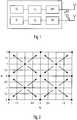
1 eine Sendeanordnung mit Phasenunstetigkeiten;2 die Konstellation einer Zweiantennen-Sendeanordnung;3 das zu betrachtende Viertel der Konstellation gemäß2 ;4 SEVM-Verläufe möglicher Vektoren;5 die Abhängigkeit des gesamten SEVMrms von der Standardabweichung des normalverteilten relativen Phasenfehlers;6 das Konstellationsdiagramm der Superposition von Sendesignalen;7 SEVM-Verläufe für den Fall der Gleichverteilung;8 die Abhängigkeit des gesamten EVMrms von der Standardabweichung des gleichverteilten relativen Phasenfehlers und9 ein Blockschaltbild der SEVM-Messung.
1 a transmission arrangement with phase discontinuities;2 the constellation of a two-antenna transmission arrangement;3 the quarter to be considered according to theconstellation 2 ;4th SEVM courses of possible vectors;5 the dependence of the entire SEVMrms on the standard deviation of the normally distributed relative phase error;6th the constellation diagram of the superposition of transmission signals;7th SEVM curves for the case of uniform distribution;8th the dependence of the entire EVMrms on the standard deviation of the uniformly distributed relative phase error and9 a block diagram of the SEVM measurement.
Für messtechnische Zwecke kann der Einfluss des relativen Phasenfehlers auf die Eigenschaften eines Mehrantennen-Senders am Beispiel eines WiMax IEEE 802.16 Signals untersucht werden. Zu diesem Zweck wird erst das bekannte Alamouti-Verfahren aus Alamouti,
Das von Alamouti vorgeschlagene Sendediversitätsverfahren bietet eine aufwandsreduzierte Alternative für das bekannte Empfangsdiversitätsverfahen MRC (Maximum Ratio Combining). Das Verfahren von Alamouti erzielt ebenso eine Diversität zweiter Ordnung, die im Gegensatz zum MRC Verfahren am Sender implementiert wird. Die Sendeanordnung wurde von Alamouti vorgestellt.The transmit diversity method proposed by Alamouti offers a reduced-effort alternative to the known receive diversity method MRC (Maximum Ratio Combining). The Alamouti method also achieves second-order diversity, which, in contrast to the MRC method, is implemented at the transmitter. The transmission arrangement was presented by Alamouti.
Gemäß Alamouti betrachtet man nach der Übertragung über einen DISO (Dual-Input-Single-Output) Kanal am Empfänger zwei aufeinander folgende Modulationssymbole. Vereinfacht sind die beiden empfangenen Symbole in der Matrixform durch die Gleichung (1) gegeben.
Die Matrix HAI wird Alamouti-Matrix genannt und ist eine skalierte unitäre Matrix. Zur Detektion der beiden gesendeten OFDM-Symbole multipliziert man den Empfangsvektor mit der Hermiteschen der Alamouti-Matrix. Das Ergebnis ist in Gleichungen (2) und (3) gezeigt. Es wird deutlich, dass sich die Symbole im Idealfall ohne Übersprechen detektieren lassen und jedes Symbol von beiden Kanalkoeffizienten optimal profitiert.

Das Alamouti-Verfahren ist ein orthogonales Verfahren, da die Matrix
Bei der realen (d.h. nicht-idealen) Kanalschätzung im Empfänger wird nun angenommen, dass es zu einem Phasenfehler kommt. Die geschätzten Kanalwerte lassen sich somit wie folgt beschreiben:
Multipliziert man nun die empfangenen Symbole mit der Hermiteschen der Kanal-Matrix, die den beschriebenen Schätzfehler aufweist, so erhält man:

Daraus ergeben sich die Schätzwerte für die gesendeten Symbole wie folgt:
Durch die nicht-ideale Kanalschätzung geht offensichtlich die Orthogonalität verloren. Es wird deutlich, dass sich die empfangenen Symbole nicht mehr ideal, d.h. nicht mehr frei von Übersprechen, detektieren lassen. Es bleibt festzuhalten, dass das Alamouti-Verfahren gegenüber nichtidealer Kanalschätzung empfindlich ist. Es wurde bisher eine kohärente Phasenbeziehung am Mehrantennensender vorausgesetzt. Im Folgenden wird gezeigt, dass ein relativer Phasenfehler zwischen den Sendeantennen ebenso einen negativen Einfluss auf das Systemleistungsverhalten verursacht.The orthogonality is obviously lost due to the non-ideal channel estimation. It becomes clear that the symbols received are no longer ideal, i.e. no longer free from crosstalk, detect. It should be noted that the Alamouti method is sensitive to non-ideal channel estimation. A coherent phase relationship at the multi-antenna transmitter was previously assumed. In the following it is shown that a relative phase error between the transmitting antennas also has a negative influence on the system performance.
Bisher wurde der Einfluss eines Phasenfehlers bei der Kanalschätzung auf die Orthogonalität und das Leistungsverhalten eines Alamouti-Empfängers untersucht. Im Folgenden wird die potentielle Störung näher betrachtet, die man sich durch eine nicht-kohärente Phasenbeziehung zwischen den Sendeantennen bei einer Alamouti-Übertragung einhandelt. Für eine erste Betrachtung wird angenommen, die Phase zweier Sendesignale unterscheidet sich um einen zufälligen Phasenoffset. Es reicht aus, nur den Phasenoffset zu betrachten, da angenommen wird, dass eines der beteiligten Sendesignale ein Referenzsymbol umfasst, wie dies z.B. bei einem WiMAX Mehrfachsendersystem nach IEEE 802.16 mit der sog. Präamble der Fall ist. Es ist deshalb auch unerheblich, ob alle Sendepfade von einem gemeinsamen Oszillator oder jeweils eigenen Oszillatoren betrieben werden. Die Senderanordnung ist in Gleichung (8) sowie in
Betrachtet man - insbesondere bei dem hier betrachteten OFDM-Signal - die Verhältnisse im Frequenzbereich, entspricht die zeitliche Multiplikation mit dem zeitvarianten Phasenoffsets einer Faltungsoperation. Nimmt man - wie Alamouti - an, dass der Phasenfehler im Sender für die Dauer von zwei Modulationssymbolen konstant bleibt, so ergeben sich die beiden aufeinander folgenden Sendesymbole (bzw. Empfangssymbole bei sonst fehlerfreier Übertragung) im Frequenzbereich zu den ungeraden und geraden Zeitpunkten wie folgt:
Dabei sind R2n-1(p) und R2n(p) die tatsächlich empfangbaren OFDM-Symbole zu den ungeraden und geraden Zeitpunkten, p wird dem aktuellen Träger innerhalb eines OFDM-Symbols zugeordnet. Bezüglich der Gleichung (9) erfolgt die Auswertung dieser Symbole im Frequenzbereich. Da die Faltung eine Verbreiterung der Trägersignale bewirkt, kommt es zu Inter-Träger-Interferenzen (ICI). Diese Interferenzen sind auf die gegenseitige Störung, d.h. auf die bereits am Sender zerstörte Orthogonalität der Trägersignale zurückzuführen. Es ist festzustellen, dass ein zeitvarianter Phasenfehler eine Verbreiterung der Trägersignale aufgrund der Faltung im Frequenzbereich bewirkt und damit auch die Orthogonalität der Trägersignale zerstört.R2n-1 (p) and R2n (p) are the OFDM symbols that can actually be received at the odd and even times, p is assigned to the current carrier within an OFDM symbol. With regard to equation (9), these symbols are evaluated in the frequency domain. Since the convolution causes a broadening of the carrier signals, there is inter-carrier interference (ICI). This interference is due to the mutual interference, ie to the orthogonality of the carrier signals that has already been destroyed at the transmitter. It should be noted that a time-variant phase error causes a broadening of the carrier signals due to the convolution in the frequency range and thus also destroys the orthogonality of the carrier signals.
Betrachtet man nun die Faltung in Gleichung (9) genauer, so stellt man fest, dass allein die Zeitvarianz des Phasenrauschens eine Interträgerinterferenz verursacht. Nimmt man jedoch an, dass der Phasenfehler für die Dauer der Kanalschätzung, also für die Dauer eines OFDM-Rahmens, für die die Auswertung des empfangenen Signals erfolgt, konstant bleibt, so nimmt Gleichung (9) die folgende Form an:
Hier wurde sogar angenommen, dass die Kanalkoeffizienten für die Dauer von zwei OFDM-Symbolen konstant sind. Weil der relative Phasenfehler konstant für die Signalauswertungsdauer bleibt, können nun die OFDM-Symbole unabhängig von den einzelnen Trägern betrachtet werden, was in Gleichung (10) durch das Verschwinden von p veranschaulicht wird. Die Gleichung (10) kann nun weiter vereinfacht werden, indem man die Faltung mit einer Multiplikation ersetzt. Es ist durchaus möglich, dass der Phasenanteil nicht mehr zeitvariant, sondern als eine Konstante zu sehen ist. Gleichung (10) kann man von daher folgendermaßen umschreiben:
Gleichung (11) lässt sich weiter in Matrixform darstellen:
Nun multipliziert man die empfangenen Symbole mit der Hermiteschen der Alamouti-Matrix, deren Werte man nach der Kanalschätzung bekommt, um die Daten am Empfänger wieder zu trennen:
Das Ergebnis ist besonders interessant für messtechnische Zwecke. Es zeigt nämlich, dass, solange der relative Phasenfehler am Sender für die Dauer der Signalauswertung, also in dem Fall für die Dauer der Kanalschätzung, zeitinvariant bleibt, die Symbole am Empfänger ohne Übersprechen wieder separiert werden können. Dieses Ergebnis ist aufgrund der Diagonalstruktur der oberen Matrix festzustellen. Es ist von großem Interesse, messtechnisch festzustellen, ob es eine Zeitvarianz bezüglich der relativen Phase zwischen den Sendeantennen gibt, um somit ein Qualitätsurteil über den Mehrantennensender zu ermöglichen.The result is particularly interesting for metrological purposes. It shows that as long as the relative phase error at the transmitter remains time-invariant for the duration of the signal evaluation, i.e. in this case for the duration of the channel estimation, the symbols can be separated again at the receiver without crosstalk. This result is due to the diagonal structure of the upper matrix. It is of great interest to establish metrologically whether there is a time variance with regard to the relative phase between the transmitting antennas, in order to enable a quality assessment of the multi-antenna transmitter.
Für die weiteren Betrachtungen wird angenommen, dass der relative Phasenfehler zeitvariant, also unterschiedlich für alle OFDM-Symbole ist, allerdings für die Dauer eines OFDM-Symbols konstant bleibt, so dass man die Faltung in Gleichung (9) mit einer Multiplikation ersetzen kann. Es wird nun festgestellt, welchen Einfluss ein solcher zeitvarianter Phasenfehler auf das Leistungsverhalten des Senders hat. Es wird ein Messverfahren vorgeschlagen, das auf der bekannten EVM-Messung basiert, welches aber speziell für Mehrantennensender modifiziert wird.For further considerations, it is assumed that the relative phase error is time-variant, i.e. different for all OFDM symbols, but remains constant for the duration of an OFDM symbol, so that the convolution in equation (9) can be replaced with a multiplication. It is now determined what influence such a time-variant phase error has on the performance of the transmitter. A measurement method is proposed that is based on the known EVM measurement, but which is specially modified for multi-antenna transmitters.
Im Weiteren wird der Zusammenhang zwischen einem relativen, zeitvarianten Phasenfehler bzw. die ihn beschreibenden statistischen Parameter dessen Verteilungsdichte und einer noch zu definierenden Superposition-Error-Vektor-Magnitude SEVM, hergeleitet. Wie bereits erwähnt, kann z.B. bei einem WiMAX Signal die die Präambel führende Sendeantenne als Referenz genutzt werden. Somit können die Betrachtungen allein auf die Phasendifferenz reduziert werden. Es werden exemplarisch zwei verschiedene Verteilungen des relativen Phasenfehlers angenommen. Zunächst wird eine mittelwertfreie Normalverteilung, danach eine Gleichverteilung der Phasendifferenz angenommen. Die Ergebnisse werden dann verglichen. Für die Normalverteilung gilt somit:
Nun wird eine praktikable Definition der SEVM für den Fall eines Mehrantennen-Senders vorgestellt. Dazu wird exemplarisch eine QPSK Modulation betrachtet, d.h. es gibt vier mögliche Konstellationspunkte pro Sendeantenne. Weil die Symbole von zwei Antennen (z.B. nach dem Alamouti-Verfahren) addiert werden, ist jede der vier Konstellationspunkte einer Antenne ein möglicher Ausgangspunkt für die weiteren vier Modulationssymbole. Diese Anordnung wird in der
Werden alle Konstellationspunkte als gleichwahrscheinlich angenommen, so kann man sich auf die Betrachtung eines Quadranten beschränken, wie gezeigt in
Allgemein ist das EVM als Quotient aus dem Betrag des Fehlervektors (Differenzvektor aus IST- und SOLL-Vektor) und dem Betrag des SOLL-Vektors definiert. Geht man von der in


Bezüglich der Definition kann der SEVM für einen bestimmten Zeitpunkt und unterschiedlich für die erwähnten vier Möglichkeiten angegeben werden als:


Um eine Aussage über das Leistungsverhalten eines Senders treffen zu können, definiert man nun den SEVMrms wie folgt:
Für die Menge möglicher Vektoren ergibt sich:


Für eine zufällige Folge des normalverteilten Phasenoffsets ist eine lineare Zunahme des SEVMrms mit steigender Standardabweichung zu beobachten. Ein Beispiel der SEVM-Folgen für eine Standardabweichung von 2° und für die vier Konstellationsmöglichkeiten ist in
Der gesamte SEVMrms beträgt damit auch 1,75%. Obwohl der SEVMrms klein für kleine Standardabweichungen bleibt, ist der maximale Wert von SEVM nach
Die Konstellation der Superposition von Sendesignalen ist für den Fall einer Standardabweichung des relativen Phasenfehlers von 5° in
Analog kann gezeigt werden, dass sich ähnliche Werte für die SEVM für beliebige QAM-Modulation ergeben. Dabei ist zu erwähnen, dass, obwohl die SEVM für beliebige QAM Konstellation gleich bleibt, natürlich die Wahrscheinlichkeit einer Fehldetektion im Empfänger mit steigendem Grad der QAM-Modulation steigt.Similarly, it can be shown that similar values result for the SEVM for any QAM modulation. It should be mentioned here that, although the SEVM remains the same for any QAM constellation, the probability of a false detection in the receiver naturally increases as the degree of QAM modulation increases.
Es wurde gezeigt, dass es einen direkten Zusammenhang zwischen dem relativen Phasenfehler und der vorgestellten SEVM gibt. Die SEVM-Messung bringt eine Aussage über die Eigenschaften eines Mehrantennen-Senders für beliebige Sendediversitäts-Kodierung. Allein ein Referenzsymbol, wie z.B. die Präambel in einem WiMAX Signal exklusiv auf einer der Sendeantennen, wird vorausgesetzt. Die Ergebnisse der SEVM-Messung können unmittelbar auf die imperfekte Phasenbeziehungen zwischen den Sendeantennen zurückgeführt werden.It was shown that there is a direct relationship between the relative phase error and the SEVM presented. The SEVM measurement provides information about the properties of a multi-antenna transmitter for any transmission diversity coding. Just a reference symbol, such as the preamble in a WiMAX signal exclusively on one of the transmitting antennas is assumed. The results of the SEVM measurement can be traced back directly to the imperfect phase relationships between the transmitting antennas.
Im Folgenden wird ein möglicher Messaufbau beschrieben. Zusätzlich wird eine einfache, aber aussagekräftige Messmethode zur Beurteilung der Eigenschaften eines Mehrantennensenders vorgestellt. Im Allgemeinen kann das Verfahren für beliebige Anzahl der Sendeantennen und jede Art der Modulation implementiert werden. Der Aufwand steigt jedoch linear mit der Anzahl der Antennen und exponentiell mit steigendem Grad der Modulation (im Allgemeinen N-QAM). Das hier gezeigte Verfahren ist speziell für ein WiMax Signal gedacht, wobei jeweils eine Sendeantenne exklusiv mit einer Präambel ausgerüstet wird. Die Präambel wird zur Phasensynchronisation und Phasenentzerrung herangezogen. Die Modulationssymbole der mit der Präambel ausgerüsteten Sendeantenne können somit als Referenz für die Symbole einer weiteren Antenne betrachtet werden.A possible measurement setup is described below. In addition, a simple but meaningful measurement method for assessing the properties of a multi-antenna transmitter is presented. In general, the method can be implemented for any number of transmission antennas and any type of modulation. However, the effort increases linearly with the number of antennas and exponentially with an increasing degree of modulation (generally N-QAM). The method shown here is specially designed for a WiMax signal, with each transmitting antenna being exclusively equipped with a preamble. The preamble is used for phase synchronization and phase equalization. The modulation symbols of the transmitting antenna equipped with the preamble can thus be viewed as a reference for the symbols of a further antenna.
Die SEVM-Messung gilt für jede Art der Raum-Zeit-Kodierung am Sender, also nicht nur für das beschriebene Alamouti-Verfahren. Allein die Präambel muss dem Messempfänger bekannt sein. Des Weiteren müssen dem Messempfänger die beteiligten Modulationsarten bekannt sein. Damit sind die SOLL-Vektoren für die SEVM-Messung eindeutig festgelegt.The SEVM measurement applies to every type of space-time coding on the transmitter, i.e. not only to the Alamouti method described. Only the preamble must be known to the measuring receiver. The test receiver must also know the types of modulation involved. This clearly defines the NOMINAL vectors for the SEVM measurement.
Ein weiterer Vorteil ist, dass die Messung ohne Diversitätsdecodierung (Equalization) am Empfänger durchgeführt wird. Dem Empfänger muss nicht bekannt sein, welches MIMO-Sendeverfahren verwendet wird. Das SEVM-Ergebnis wird direkt aus der Überlagerung der beiden Signale im komplexen Signalraum festgestellt.Another advantage is that the measurement is carried out without diversity decoding (equalization) at the receiver. The recipient does not need to know which MIMO transmission method is used. The SEVM result is determined directly from the superposition of the two signals in the complex signal space.
Um die Eigenschaften des Senders beurteilen zu können, muss nun der Einfluss des Mess-Kanals eliminiert werden. Man geht davon aus, dass alle Kanalkoeffizienten in dem Fall gleich Eins sein müssen. Dazu wird das System vor der Durchführung der Messung entsprechend kalibriert, so dass nur der Einfluss des relativen Phasenfehlers zwischen den Signalen beobachtet wird.In order to be able to assess the characteristics of the transmitter, the influence of the measuring channel must now be eliminated. It is assumed that all channel coefficients must be equal to one in this case. For this purpose, the system is calibrated accordingly before the measurement is carried out so that only the influence of the relative phase error between the signals is observed.
Der Empfänger bezieht sich auf das mit der Präambel gesendete Signal und stellt zu diesem Zeitpunkt den Referenzsignalraum für die Superposition der von mehreren Antennen ankommenden Signale her. Nach der Erstellung der Konstellation des Mehrfach-Signals können nun die IST-Vektoren berechnet werden. Da mit der Modulationsart auch die SOLL-Vektoren dem Empfänger bekannt sind, werden die SEVM-Werte nach der vorgeschlagenen Definition berechnet.The receiver refers to the signal sent with the preamble and at this point in time establishes the reference signal space for the superposition of the signals arriving from several antennas. After creating the constellation of the multiple signal, the ACTUAL vectors can now be calculated. Since the TARGET vectors are known to the receiver along with the modulation type, the SEVM values are calculated according to the proposed definition.
Eine wichtige Frage ist, welcher SEVM Bereich für einen guten Empfänger angenommen werden kann. Hier kann die Wahrscheinlichkeitsbetrachtung hilfreich sein. Es kann bewiesen werden, dass der relative Phasenfehler zwischen den Signalen wie ein AWGN-Kanal für das entzerrte (equalized) Signal wirkt und der Betrachtung des Wahrscheinlichkeitstheorems untergebracht werden kann. Für ein System wie in
Die Erfindung ist nicht auf das in der Zeichnung dargestellte Ausführungsbeispiel beschränkt. Alle vorstehend beschriebenen und in der Zeichnung dargestellten Merkmale sind beliebig miteinander kombinierbar.The invention is not limited to the embodiment shown in the drawing. All of the features described above and shown in the drawing can be combined with one another as required.
Claims (10)
Translated fromGerman
Priority Applications (6)
| Application Number | Priority Date | Filing Date | Title |
|---|---|---|---|
| DE102006057316.1ADE102006057316B4 (en) | 2006-12-05 | 2006-12-05 | Measurement method and device for assessing an OFDM multi-antenna transmitter |
| JP2009539617AJP2010512080A (en) | 2006-12-05 | 2007-10-11 | Measurement method and apparatus for evaluating an OFDM multi-antenna transmitter |
| PCT/EP2007/008858WO2008067869A1 (en) | 2006-12-05 | 2007-10-11 | Measuring method and apparatus for assessing an ofdm multiantenna transmitter |
| US12/296,548US20090274203A1 (en) | 2006-12-05 | 2007-10-11 | Measuring Method and Device for Evaluating an OFDM-Multi-Antenna Transmitter |
| KR1020087025222AKR100976048B1 (en) | 2006-12-05 | 2007-10-11 | ODF-multi-antenna transmitter evaluation method and evaluation device |
| EP07818929AEP2100387A1 (en) | 2006-12-05 | 2007-10-11 | Measuring method and apparatus for assessing an ofdm multiantenna transmitter |
Applications Claiming Priority (1)
| Application Number | Priority Date | Filing Date | Title |
|---|---|---|---|
| DE102006057316.1ADE102006057316B4 (en) | 2006-12-05 | 2006-12-05 | Measurement method and device for assessing an OFDM multi-antenna transmitter |
Publications (2)
| Publication Number | Publication Date |
|---|---|
| DE102006057316A1 DE102006057316A1 (en) | 2008-06-12 |
| DE102006057316B4true DE102006057316B4 (en) | 2020-12-03 |
Family
ID=38884653
Family Applications (1)
| Application Number | Title | Priority Date | Filing Date |
|---|---|---|---|
| DE102006057316.1AActiveDE102006057316B4 (en) | 2006-12-05 | 2006-12-05 | Measurement method and device for assessing an OFDM multi-antenna transmitter |
Country Status (6)
| Country | Link |
|---|---|
| US (1) | US20090274203A1 (en) |
| EP (1) | EP2100387A1 (en) |
| JP (1) | JP2010512080A (en) |
| KR (1) | KR100976048B1 (en) |
| DE (1) | DE102006057316B4 (en) |
| WO (1) | WO2008067869A1 (en) |
Families Citing this family (2)
| Publication number | Priority date | Publication date | Assignee | Title |
|---|---|---|---|---|
| DE502008002482D1 (en)* | 2008-07-31 | 2011-03-10 | Rohde & Schwarz | Method and apparatus for producing a quantizable phase coherence between two high-frequency signals |
| DE102014201755B4 (en) | 2014-01-31 | 2021-06-10 | Rohde & Schwarz GmbH & Co. Kommanditgesellschaft | Measurement system and measurement method with broadband synchronization and narrowband signal analysis |
Citations (1)
| Publication number | Priority date | Publication date | Assignee | Title |
|---|---|---|---|---|
| DE102004038834A1 (en)* | 2004-08-10 | 2006-02-23 | Siemens Ag | A method of generating preamble and signaling structures in a MIMO-OFDM transmission system |
Family Cites Families (8)
| Publication number | Priority date | Publication date | Assignee | Title |
|---|---|---|---|---|
| US7548506B2 (en)* | 2001-10-17 | 2009-06-16 | Nortel Networks Limited | System access and synchronization methods for MIMO OFDM communications systems and physical layer packet and preamble design |
| JP3997890B2 (en)* | 2001-11-13 | 2007-10-24 | 松下電器産業株式会社 | Transmission method and transmission apparatus |
| US7035343B2 (en)* | 2002-01-31 | 2006-04-25 | Qualcomm Inc. | Closed loop transmit diversity antenna verification using trellis decoding |
| US7742533B2 (en)* | 2004-03-12 | 2010-06-22 | Kabushiki Kaisha Toshiba | OFDM signal transmission method and apparatus |
| US20060058022A1 (en)* | 2004-08-27 | 2006-03-16 | Mark Webster | Systems and methods for calibrating transmission of an antenna array |
| US8019012B2 (en)* | 2004-12-28 | 2011-09-13 | Motorola Mobility, Inc. | Method and controller for syncronizing a wireless communication device and network |
| US7564917B2 (en)* | 2005-11-01 | 2009-07-21 | Intel Corporation | Multicarrier receiver and method for generating common phase error estimates for use in systems that employ two or more transmit antennas with independent local oscillators |
| JP4406398B2 (en)* | 2005-12-26 | 2010-01-27 | 株式会社東芝 | OFDM signal transmission method and transmitter, and OFDM signal receiver |
- 2006
- 2006-12-05DEDE102006057316.1Apatent/DE102006057316B4/enactiveActive
- 2007
- 2007-10-11USUS12/296,548patent/US20090274203A1/ennot_activeAbandoned
- 2007-10-11KRKR1020087025222Apatent/KR100976048B1/enactiveActive
- 2007-10-11JPJP2009539617Apatent/JP2010512080A/enactivePending
- 2007-10-11WOPCT/EP2007/008858patent/WO2008067869A1/enactiveApplication Filing
- 2007-10-11EPEP07818929Apatent/EP2100387A1/ennot_activeWithdrawn
Patent Citations (1)
| Publication number | Priority date | Publication date | Assignee | Title |
|---|---|---|---|---|
| DE102004038834A1 (en)* | 2004-08-10 | 2006-02-23 | Siemens Ag | A method of generating preamble and signaling structures in a MIMO-OFDM transmission system |
Non-Patent Citations (1)
| Title |
|---|
| LEI,J.,GANG,D.,et.al.:EVM Measurement Algorithm for OFDM Transmitters. In: Iternational Symposium on Communications and Information Technologies (ISCIT'06), October 2006, S.102-107.* |
Also Published As
| Publication number | Publication date |
|---|---|
| KR20090031662A (en) | 2009-03-27 |
| KR100976048B1 (en) | 2010-08-17 |
| DE102006057316A1 (en) | 2008-06-12 |
| US20090274203A1 (en) | 2009-11-05 |
| JP2010512080A (en) | 2010-04-15 |
| EP2100387A1 (en) | 2009-09-16 |
| WO2008067869A1 (en) | 2008-06-12 |
Similar Documents
| Publication | Publication Date | Title |
|---|---|---|
| EP1402657B1 (en) | Adaptive signal processing method in a mimo system | |
| DE60121397T2 (en) | Adaptive space diversity and time diversity for OFDM | |
| DE60021524T2 (en) | OFDM diversity transmission | |
| DE60217706T2 (en) | STFBC CODING / DECODING DEVICE AND METHOD IN AN OFDM MOBILE COMMUNICATION SYSTEM | |
| DE60219605T2 (en) | METHOD AND DEVICE FOR USING CHANNEL CONDITIONING INFORMATION (CSI) IN A WIRELESS COMMUNICATION SYSTEM | |
| DE602004005896T2 (en) | CALIBRATION METHOD FOR OBTAINING RECIPROCITY OF BIDIRECTIONAL COMMUNICATION CHANNELS | |
| DE102012007469B4 (en) | METHOD OF CHANNEL ESTIMATION AND CHANNEL ESTIMATORS | |
| DE202006021069U1 (en) | System for channel estimation in a wireless communication system with delay diversity | |
| DE112021000830T5 (en) | Method for estimating discrete digital signals in noisy, congested wireless communication systems with CSI errors | |
| DE112006003834T5 (en) | Decoding frequency-channeled signals | |
| DE202008018251U1 (en) | Transmitter for CCFI in a wireless communication system | |
| DE102011054913B4 (en) | RECEIVER AND METHOD FOR DETECTING A PRE-CODED SIGNAL | |
| EP2510643B1 (en) | Functional variable value transmitter, functional receiver, and system in sensor networks | |
| DE102014108835B4 (en) | Method and device for interference variance estimation and interference cancellation | |
| DE60307140T2 (en) | DEVICE AND METHOD FOR THE CYCLICAL DELAY DIVERSITY | |
| DE102019135901A1 (en) | WIRELESS COMMUNICATION DEVICE AND CHANNEL ESTIMATE METHOD OF IT | |
| DE102007023881A1 (en) | Method and apparatus for detecting an un-shortened channel impulse response in an OFDM transmission system | |
| DE602004011294T2 (en) | Method and apparatus for channel estimation in an OFDM mobile communication system | |
| DE102006057316B4 (en) | Measurement method and device for assessing an OFDM multi-antenna transmitter | |
| DE69711247T2 (en) | INTERFERENCE CANCELLATION BY SIGNAL COMBINATION WITH A FREQUENCY CORRECTION | |
| EP1917752B1 (en) | Method and transmitting device for encoding data in a differential space-time block code | |
| EP1537711B1 (en) | Preamble for estimation and equalisation of asymmetries between in phase and quadrature branches in multi-carrier transmission systems | |
| DE19543622C2 (en) | Method and device for the bidirectional transmission of high-rate digital signals | |
| EP1342353B1 (en) | Method for estimating the channel properties in a communication system | |
| DE102008033553B4 (en) | Decode Alamouti-encoded WiMax signals |
Legal Events
| Date | Code | Title | Description |
|---|---|---|---|
| OM8 | Search report available as to paragraph 43 lit. 1 sentence 1 patent law | ||
| R012 | Request for examination validly filed | Effective date:20131105 | |
| R018 | Grant decision by examination section/examining division | ||
| R020 | Patent grant now final |