DE102006055641B4 - Arrangement and method for recording and reproducing images of a scene and / or an object - Google Patents
Arrangement and method for recording and reproducing images of a scene and / or an objectDownload PDFInfo
- Publication number
- DE102006055641B4 DE102006055641B4DE102006055641ADE102006055641ADE102006055641B4DE 102006055641 B4DE102006055641 B4DE 102006055641B4DE 102006055641 ADE102006055641 ADE 102006055641ADE 102006055641 ADE102006055641 ADE 102006055641ADE 102006055641 B4DE102006055641 B4DE 102006055641B4
- Authority
- DE
- Germany
- Prior art keywords
- images
- camera
- image
- depth
- resolution
- Prior art date
- Legal status (The legal status is an assumption and is not a legal conclusion. Google has not performed a legal analysis and makes no representation as to the accuracy of the status listed.)
- Expired - Fee Related
Links
Images


Classifications
- H—ELECTRICITY
- H04—ELECTRIC COMMUNICATION TECHNIQUE
- H04N—PICTORIAL COMMUNICATION, e.g. TELEVISION
- H04N13/00—Stereoscopic video systems; Multi-view video systems; Details thereof
- H04N13/10—Processing, recording or transmission of stereoscopic or multi-view image signals
- H04N13/106—Processing image signals
- H04N13/133—Equalising the characteristics of different image components, e.g. their average brightness or colour balance
- H—ELECTRICITY
- H04—ELECTRIC COMMUNICATION TECHNIQUE
- H04N—PICTORIAL COMMUNICATION, e.g. TELEVISION
- H04N13/00—Stereoscopic video systems; Multi-view video systems; Details thereof
- H04N13/20—Image signal generators
- H04N13/204—Image signal generators using stereoscopic image cameras
- H04N13/25—Image signal generators using stereoscopic image cameras using two or more image sensors with different characteristics other than in their location or field of view, e.g. having different resolutions or colour pickup characteristics; using image signals from one sensor to control the characteristics of another sensor
- H—ELECTRICITY
- H04—ELECTRIC COMMUNICATION TECHNIQUE
- H04N—PICTORIAL COMMUNICATION, e.g. TELEVISION
- H04N13/00—Stereoscopic video systems; Multi-view video systems; Details thereof
- H04N13/30—Image reproducers
- H04N13/388—Volumetric displays, i.e. systems where the image is built up from picture elements distributed through a volume
- H04N13/395—Volumetric displays, i.e. systems where the image is built up from picture elements distributed through a volume with depth sampling, i.e. the volume being constructed from a stack or sequence of 2D image planes
- H—ELECTRICITY
- H04—ELECTRIC COMMUNICATION TECHNIQUE
- H04N—PICTORIAL COMMUNICATION, e.g. TELEVISION
- H04N13/00—Stereoscopic video systems; Multi-view video systems; Details thereof
- H04N13/10—Processing, recording or transmission of stereoscopic or multi-view image signals
- H04N13/106—Processing image signals
- H04N13/111—Transformation of image signals corresponding to virtual viewpoints, e.g. spatial image interpolation
- H—ELECTRICITY
- H04—ELECTRIC COMMUNICATION TECHNIQUE
- H04N—PICTORIAL COMMUNICATION, e.g. TELEVISION
- H04N13/00—Stereoscopic video systems; Multi-view video systems; Details thereof
- H04N13/10—Processing, recording or transmission of stereoscopic or multi-view image signals
- H04N13/194—Transmission of image signals
- H—ELECTRICITY
- H04—ELECTRIC COMMUNICATION TECHNIQUE
- H04N—PICTORIAL COMMUNICATION, e.g. TELEVISION
- H04N13/00—Stereoscopic video systems; Multi-view video systems; Details thereof
- H04N13/20—Image signal generators
- H04N13/204—Image signal generators using stereoscopic image cameras
- H04N13/239—Image signal generators using stereoscopic image cameras using two 2D image sensors having a relative position equal to or related to the interocular distance
- H—ELECTRICITY
- H04—ELECTRIC COMMUNICATION TECHNIQUE
- H04N—PICTORIAL COMMUNICATION, e.g. TELEVISION
- H04N13/00—Stereoscopic video systems; Multi-view video systems; Details thereof
- H04N13/20—Image signal generators
- H04N13/204—Image signal generators using stereoscopic image cameras
- H04N13/243—Image signal generators using stereoscopic image cameras using three or more 2D image sensors
- H—ELECTRICITY
- H04—ELECTRIC COMMUNICATION TECHNIQUE
- H04N—PICTORIAL COMMUNICATION, e.g. TELEVISION
- H04N13/00—Stereoscopic video systems; Multi-view video systems; Details thereof
- H04N13/20—Image signal generators
- H04N13/282—Image signal generators for generating image signals corresponding to three or more geometrical viewpoints, e.g. multi-view systems
- H—ELECTRICITY
- H04—ELECTRIC COMMUNICATION TECHNIQUE
- H04N—PICTORIAL COMMUNICATION, e.g. TELEVISION
- H04N13/00—Stereoscopic video systems; Multi-view video systems; Details thereof
- H04N13/20—Image signal generators
- H04N13/286—Image signal generators having separate monoscopic and stereoscopic modes
- H—ELECTRICITY
- H04—ELECTRIC COMMUNICATION TECHNIQUE
- H04N—PICTORIAL COMMUNICATION, e.g. TELEVISION
- H04N13/00—Stereoscopic video systems; Multi-view video systems; Details thereof
- H04N13/30—Image reproducers
- H04N13/302—Image reproducers for viewing without the aid of special glasses, i.e. using autostereoscopic displays
- H—ELECTRICITY
- H04—ELECTRIC COMMUNICATION TECHNIQUE
- H04N—PICTORIAL COMMUNICATION, e.g. TELEVISION
- H04N13/00—Stereoscopic video systems; Multi-view video systems; Details thereof
- H04N13/30—Image reproducers
- H04N13/332—Displays for viewing with the aid of special glasses or head-mounted displays [HMD]
- H04N13/344—Displays for viewing with the aid of special glasses or head-mounted displays [HMD] with head-mounted left-right displays
- H—ELECTRICITY
- H04—ELECTRIC COMMUNICATION TECHNIQUE
- H04N—PICTORIAL COMMUNICATION, e.g. TELEVISION
- H04N19/00—Methods or arrangements for coding, decoding, compressing or decompressing digital video signals
- H04N19/50—Methods or arrangements for coding, decoding, compressing or decompressing digital video signals using predictive coding
- H04N19/597—Methods or arrangements for coding, decoding, compressing or decompressing digital video signals using predictive coding specially adapted for multi-view video sequence encoding
- H—ELECTRICITY
- H04—ELECTRIC COMMUNICATION TECHNIQUE
- H04N—PICTORIAL COMMUNICATION, e.g. TELEVISION
- H04N13/00—Stereoscopic video systems; Multi-view video systems; Details thereof
- H04N2013/0074—Stereoscopic image analysis
- H04N2013/0081—Depth or disparity estimation from stereoscopic image signals
Landscapes
- Engineering & Computer Science (AREA)
- Multimedia (AREA)
- Signal Processing (AREA)
- Testing, Inspecting, Measuring Of Stereoscopic Televisions And Televisions (AREA)
- Stereoscopic And Panoramic Photography (AREA)
- Studio Devices (AREA)
Abstract
Translated fromGermanDescription
Translated fromGermanDie Erfindung betrifft eine Anordnung und ein Verfahren zur Aufnahme und Wiedergabe von Bildern einer Szene und/oder eines Objektes. Sie sind insbesondere zur räumlich wahrnehmbaren Wiedergabe der aufgenommenen Bilder geeignet. Fernerhin betrifft die Erfindung ein Verfahren zur Übertragung von räumlich wahrnehmbaren Bildern.The invention relates to an arrangement and a method for recording and reproducing images of a scene and / or an object. They are particularly suitable for spatially perceptible reproduction of the recorded images. Furthermore, the invention relates to a method for transmitting spatially perceivable images.
Zum Aufnehmen von 3D-Bildinformationen gibt es momentan im Wesentlichen drei grundlegend verschiedene Verfahren und die dazugehörigen Anordnungen:
Erstens, die klassische Stereo-Kamera, bestehend aus zwei gleichartigen Kameras für jeweils ein linkes und ein rechtes Bild. Für eine hochauflösende Wiedergabe sind hier jedoch auch hochauflösende Kamerasysteme notwendig. Für Mehrkanal-Systeme wird eine Interpolation der Zwischenansichten notwendig. Dabei werden Artefakte vor allem in den mittleren Ansichten sichtbar.For capturing 3D image information, there are currently essentially three fundamentally different methods and the associated arrangements:
First, the classic stereo camera, consisting of two similar cameras, each for a left and a right image. For a high-resolution reproduction, however, high-resolution camera systems are also necessary here. For multi-channel systems, interpolation of the intermediate views becomes necessary. Artifacts become visible especially in the middle views.
Zweitens, die Verwendung eines Multiview-Kamera-Systems. Der Vorteil hier gegenüber der Stereo-Kamera ist die korrekte Bildwiedergabe für Mehrkanal-Systeme. Es werden insbesondere keine Interpolationen notwendig. Nachteilig ist jedoch der hohe Aufwand, der betrieben werden muss, um eine exakte Ausrichtung der Kameras zueinander zu realisieren. Der erhöhte Kostenfaktor durch die Verwendung mehrerer Kameras, die darüber hinaus weitere Probleme nach sich ziehen, wie unterschiedliche Weiß/Farb/Geometriewerte, die wieder entsprechend ausgeglichen werden müssen, ist nachteilig. Als nachteilig ist es ebenfalls anzusehen, dass bei diesem Verfahren eine extrem hohe Datenrate bewältigt werden muss.Second, the use of a multiview camera system. The advantage here compared to the stereo camera is the correct image reproduction for multichannel systems. In particular, no interpolations are necessary. However, a disadvantage is the high expense that must be operated in order to realize an exact alignment of the cameras to each other. The increased cost factor through the use of multiple cameras, which also entail further problems, such as different white / color / geometry values, which must be compensated again accordingly, is disadvantageous. It is also disadvantageous that an extremely high data rate has to be mastered in this method.
Drittens, die Verwendung einer Tiefen-Kamera. Hierbei kommt eine Farbkamera gemeinsam mit einem Tiefensensor, der die zyklopische Tiefeninformation der aufzunehmenden Szene registriert, zum Einsatz. Neben dem, dass ein Tiefensensor relativ teuer ist, ist nachteilig, dass diese oftmals nicht sehr exakt arbeiten und/oder kein vertretbarer Kompromiss zwischen Genauigkeit und Geschwindigkeit erreicht wird. Eine generelle Extrapolation wird notwendig, wobei insbesondere in den äußeren Ansichten Artefakte nicht auszuschließen sind und generell Verdeckungsartefakte nicht kaschiert werden können.Third, the use of a depth camera. In this case, a color camera is used together with a depth sensor which registers the cyclopean depth information of the scene to be recorded. In addition to the fact that a depth sensor is relatively expensive, it is disadvantageous that these often do not work very accurately and / or a reasonable compromise between accuracy and speed is achieved. A general extrapolation becomes necessary, whereby artefacts can not be ruled out, especially in the outer views, and general occlusion artefacts can not be concealed.
Mit der
Bei der
In der Schrift Kim K.-T. et al. ”Synthesis of a high-resolution 3D-stereoscopic image pair from a high-resolution monoscopic image and a low-resolution depth map”, SPIE, Band 3295, Januar 1998, Seiten 76–86, wird ein Verfahren zum Erstellen von zwei oder mehr Bildern vorgestellt, wobei die Ausgangsbasis drei (zunächst gleiche) Bilder sind. Zunächst werden die äußeren Bilder in der Auflösung verringert und monochrom konvertiert. Dann wird eine Disparitätskarte erzeugt, und zwar aus dem linken, rechten Bild und dem mittleren Bild. Bei der Ansichtenrekonstruktion (Interpolation bzw. Synthesizing Left/Right Images) wird jedoch nur eine Tiefenkarte verwendet, und auch nur Bildinformation der mittleren Kamera, nicht aber die der äußeren Kameras. Bezüglich Okklusionen (also Verdeckungen) wird hier offenbart, lediglich die im mittleren hochauflösenden Bild vorhandenen Bildanteile für Interpolationen zu nutzen. Es wird ferner vorgeschlagen, Daten über Okklusionen separat zu ermitteln und auf der Empfängerseite zu nutzen. Nachteilig ist hierbei, dass die so erhaltene Okklusionsinformation rudimentär bleibt, da nicht Bildinformation aus dem linken und rechten Bild einfließen.In the writing Kim K.-T. et al. "Synthesis of a high-resolution monochromatic image-pair from a high-resolution monoscopic image and a low-resolution depth map", SPIE, vol. 3295, January 1998, pages 76-86, will provide a method for creating two or more Pictures, where the starting point is three (initially the same) pictures. First, the outer images are reduced in resolution and monochrome converted. Then a disparity map is generated from the left, right, and middle images. However, in view reconstruction (interpolation or synthesisizing left / right images) only one depth map is used, and also only image information of the middle camera, but not of the outer cameras. With regard to occlusions (ie obscurations), it is disclosed here that only the image components present in the middle high-resolution image are to be used for interpolations. It is also proposed to separately determine data on occlusions and to use them on the receiver side. The disadvantage here is that the occlusion information thus obtained remains rudimentary, since not image information from the left and right image flow.
Der Erfindung liegt die Aufgabe zugrunde, eine neue Möglichkeit aufzuzeigen, durch die es mit möglichst geringem Aufwand gelingt, Aufnahmen von realen Szenen und/oder Objekten zu erstellen, um sie nachfolgend dreidimensional in zwei oder mehr Ansichten räumlich wahrnehmbar wiederzugeben. Weiterhin ist es Aufgabe der Erfindung, ein geeignetes Verfahren zur Übertragung von räumlich wahrnehmbaren Bildern aufzuzeigen.The invention has for its object to provide a new way by which it is possible with the least possible effort to create shots of real scenes and / or objects in order to reproduce them three-dimensionally in two or more views spatially perceptible. It is another object of the invention to provide a suitable method for transmitting spatially perceivable images.
Erfindungsgemäß wird die Aufgabe bei einer Anordnung zur Aufnahme und Wiedergabe von Bildern einer Szene und/oder eines Objektes dadurch gelöst, dass mindestens eine Hauptkamera eines ersten Kameratyps zur Aufnahme von Bildern, mindestens eine Satellitenkamera eines zweiten Kameratyps zur Aufnahme von Bildern, wobei der erste und der zweite Kameratyp sich in mindestens einem Parameter, bevorzugt der Bildauflösung, unterscheiden und eine den Kameras nachgeordnete Bildkonvertierungseinrichtung und ein 3D-Bildwiedergabegerät vorhanden sind. Haupt- und Satellitenkamera unterscheiden sich im allgemeinen, jedoch nicht zwingend, durch ihre Qualität. Die Hauptkamera ist dabei meist eine sogenannte High-Quality-Kamera, wobei Satellitenkameras zum Einsatz kommen können, die sich durch geringere Qualität auszzeichnen (z. B. Industriekameras) und damit unter anderen Parametern meist – aber nicht zwingend – auch eine niedrigere Auflösung aufweisen. Der Vorteil der Erfindung besteht im Wesentlichen darin, dass neben dem klassischen Einsatz eines Stereo-Kamerasystems, hier bestehend aus im Wesentlichen zwei identischen hochauflösenden Kameras, ein Drei-Kamera-System, bestehend aus einer zentralen High-Quality-Kamera und zwei zusätzlichen Kameras mit niedriger Auflösung, die links- bzw. rechts der Hauptkamera angeordnet sind, verwendet wird. Die Kameras sind dabei in den üblichen Grenzen bzgl. Abstand und Ausrichtung (parallele Ausrichtung oder auf einen Fokus) variierbar. Die Verwendung weiterer Satellitenkameras kann von Vorteil sein, da insbesondere bei der nachfolgenden Aufbereitung der Bilddaten Fehlinterpretationen weiter reduziert werden können. Alle Kameras können sowohl parallel als auch auf einen Punkt ausgerichtet sein. Ebenfalls möglich ist es, dass nicht alle auf einen Punkt ausgerichtet sind (Konvergenzwinkel). Die optischen Achsen der Kameras können ebenfalls sowohl in einer als auch in unterschiedlichen Ebenen liegen, wobei die Objektivmittelpunkte in einer Linie oder im Dreieck (bevorzugt gleichschenklig oder gleichseitig) angeordnet sein sollten. Eine Synchronisation der Kameras bzgl. Zoom, Blende, Fokus etc. sollte ebenso wie bzgl. der einzelnen Frames erfolgen. Die Kameras können fest oder beweglich zueinander angeordnet werden, wobei eine automatische Einstellung des Basisabstandes der Kameras ebenso wie die Konvergenzwinkel durchführbar ist.According to the invention, this object is achieved in an arrangement for recording and reproducing images of a scene and / or an object in that at least one main camera of a first type of camera for taking pictures, at least one satellite camera of a second type of camera for taking pictures, wherein the first and the second type of camera is in at least one parameter, preferably the image resolution, and an image converter means downstream of the cameras and a 3D image display apparatus are present. Main and satellite cameras are generally different but not necessarily different in quality. The main camera is usually a so-called high-quality camera, with satellite cameras can be used, which are characterized by lower quality (eg industrial cameras) and thus under other parameters usually - but not necessarily - also have a lower resolution. The advantage of the invention is essentially that in addition to the classic use of a stereo camera system, consisting here of essentially two identical high-resolution cameras, a three-camera system consisting of a central high-quality camera and two additional cameras with low resolution, which are located on the left and right of the main camera is used. The cameras can be varied within the usual limits regarding distance and orientation (parallel alignment or focus). The use of additional satellite cameras can be advantageous, since misinterpretations can be further reduced, particularly in the subsequent preparation of the image data. All cameras can be aligned both parallel and to a point. It is also possible that not all are aligned to one point (convergence angle). The optical axes of the cameras can also lie both in one and in different planes, wherein the objective centers should be arranged in a line or in the triangle (preferably isosceles or equilateral). Synchronization of the cameras with regard to zoom, aperture, focus, etc. should be the same as with respect to the individual frames. The cameras can be fixed or movable to each other, with an automatic adjustment of the base distance of the cameras as well as the convergence angle is feasible.
Von Vorteil können Adaptersysteme sein, die ein erleichtertes Anbringen, insbesondere der Satellitenkameras, an die Hauptkamera ermöglichen. Damit können gewöhnliche Kameras nachträglich als 3D-Kamera umgerüstet werden. Es ist aber ebenso denkbar, bestehende Stereokamerasysteme durch eine zusätzliche Hauptkamera zu erfindungsgemäßen 3D-Kameras umzurüsten.Advantageously, adapter systems can be used, which make it easier to attach, in particular the satellite cameras, to the main camera. This allows ordinary cameras to be retrofitted as a 3D camera. However, it is also conceivable to convert existing stereo camera systems by an additional main camera to 3D cameras according to the invention.
Fernerhin können im Strahlengang zusätzliche optische Elemente, z. B. teildurchlässige Spiegel, vorhanden sein.Furthermore, in the beam path additional optical elements, for. B. partially transparent mirror may be present.
Für besondere Ausgestaltungen kann es außerdem sinnvoll sein, die Satellitenkameras als Schwarz-Weiß-Kameras auszubilden und bevorzugt den von ihnen aufgenommenen Bildern hernach automatisch einen Farbwert zuzuweisen.For special embodiments, it may also be useful to form the satellite cameras as black and white cameras and preferably prefer to automatically assign a color value to the images taken by them.
Die Aufgabe wird auch durch ein Verfahren zur Aufnahme und Wiedergabe von Bildern einer Szene und/oder eines Objektes gelöst, welches die folgenden Schritte umfasst:
- – Erstellung von mindestens einem n-Tupel von Bildern, mit n > 1,
- – Übernahme der Bilddaten in eine Bildkonvertierungseinrichtung, in der nachfolgend eine Rektifizierung, eine Farbjustierung, der Aufbau einer Stackstruktur und eine Projektion der Stackstruktur auf eine gewünschte Ansicht durchgeführt wird, wobei mindestens eine Ansicht generiert wird, die keinem der von dem Kamerasystem aufgenommenen Bildern exakt entspricht,
- – anschließend eine Kombination der verschiedenen Ansichten entsprechend der Zuordnungsvorschrift des 3D-Displays eines 3D-Bildwiedergabegerätes erstellt wird, und
- – abschließend die Darstellung des kombinierten 3D-Bildes auf dem 3D-Display durchgeführt wird.
- Creation of at least one n-tuple of images, with n> 1,
- - Acquisition of the image data in an image converting device, in which a rectification, a color adjustment, the structure of a stack structure and a projection of the stack structure is performed on a desired view, wherein at least one view is generated that does not exactly match any of the images captured by the camera system .
- - Subsequently, a combination of the different views according to the assignment rule of the 3D display of a 3D image display device is created, and
- - Finally, the representation of the combined 3D image on the 3D display is performed.
Der Aufbau einer Stackstruktur kann auch durch sonstige anwendbare Tiefen- oder Disparitätserkennungsalgorithmen ersetzt werden, wobei dann die erkannten Tiefen- bzw. Disparitätswerte für die Erstellung von gewünschten Ansichten eingesetzt werden. Eine Stackstruktur kann allgemein einer Schichtstruktur von graphischen Elementen in unterschiedlichen Ebenen entsprechen.The structure of a stack structure can also be replaced by other applicable depth or disparity detection algorithms, in which case the detected depth or disparity values are used for the creation of desired views. A stack structure may generally correspond to a layered structure of graphical elements at different levels.
Bei der Verwendung eines 3D-Kamerasystems, bestehend aus Kameras unterschiedlicher Kameratypen mit unterschiedlichen Bildauflösungen, macht es sich erforderlich, dass nach Übernahme der Bilddaten in die Bildkonvertierungseinrichtung zunächst eine Größenanpassung vorgenommen wird. Im Ergebnis dessen liegen Bilder mit jeweils der gleichen Auflösung vor. Daran anschließend erfolgt die Rektifizierung, d. h. eine geometrische Entzerrung der Kamerabilder (Ausgleich von möglichen Linsenverzerrungen, Kameraverdrehungen, Zoomdifferenzen etc.) wird vorgenommen. Die Größenanpassung kann auch im Rahmen des Rektifizierungsprozesses erfolgen. Unmittelbar daran anschließend erfolgt eine Farbjustierung. Es werden insbesondere die Farb-/Helligkeitswerte der Kamerabilder angeglichen, so dass ein einheitliches oder zumindest ein vergleichbares Niveau zu verzeichnen ist. Für die nunmehr vorliegenden Bilddaten wird die Stackstruktur aufgebaut. Dabei werden die Eingangsbilder zeilenweise miteinander verglichen, indem sie im ersten Schritt übereinander gelegt werden. Der Zeilenvergleich kann unter Umständen auch schräg erfolgen, dies wird dann günstig sein, wenn die Kameras nicht horizontal zueinander angeordnet sind. Bei übereinanderliegenden Pixeln mit gleichen Farbwerten wird dieser gespeichert, wenn jedoch übereinanderliegende Pixel unterschiedliche Farbwerte aufweisen, dann wird kein Wert gespeichert. Danach werden die Zeilen gegeneinander in entgegengesetzte Richtungen in definierten Schritten (z. B. um ¼ oder ½ Pixel) verschoben, wobei nach jedem Schritt das Ergebnis des Vergleiches wieder gespeichert wird. Im Ergebnis liegt die dreidimensionale Stackstruktur mit den Koordinaten X, Y und Z vor, wobei X und Y den Pixelkoordinaten des Eingangsbildes entspricht, während Z den Grad der Verschiebung der Ansichten zueinander darstellt. Bei der Verwendung von zwei Kameras werden also jeweils zwei Zeilen verglichen und bei der Verwendung von drei Kameras jeweils drei Zeilen verglichen und gegeneinander verschoben. Möglich ist es, bei der Verwendung von mehreren, z. B. drei, Kameras dennoch jeweils nur zwei Zeilen miteinander zu kombinieren, wobei dann ein Abgleich der Vergleiche nochmals durchgeführt werden muss. Bei einem Vergleich von drei oder mehr Zeilen gibt es weit weniger Mehrdeutungen gegenüber dem Vergleich zwischen den zwei Zeilen lediglich zweier Eingangsbilder. Bei der sich anschließenden Optimierung der Stackstruktur geht es im Wesentlichen darum, bei mehrdeutigen Abbildungen von Bildelementen im Stack die höchst unwahrscheinlichen Kombinationen zu löschen. Dies trägt darüber hinaus zur Datenreduktion bei. Eine weitere Reduktion erhält man, indem eine Höhenprofillinie aus den verbliebenen Elementen erstellt wird, um eine eindeutige Abbildung der Farbwerte in eine diskrete Tiefebene (Z Koordinate) zu erreichen. Normalerweise schließt sich nun die Projektion der Stackstruktur auf die gewünschten Ansichten an. Dabei sollten mindestens zwei Ansichten erstellt werden, wobei eine davon immer noch einem Eingangsbild entsprechen könnte. Dies erfolgt jedoch in der Regel in Kenntnis des sich anschließenden 3D-Bildwiedergabegerätes. Die anschließende Kombination der verschiedenen bereitgestellten Ansichten entspricht der Zuordnungsvorschrift des 3D-Displays.When using a 3D camera system, consisting of cameras of different camera types with different image resolutions, it is necessary that after adoption of the image data in the image converting device first a size adjustment is made. As a result, images with the same resolution are available. This is followed by the rectification, ie a geometric equalization of the camera images (compensation for possible lens distortions, camera distortions, zoom differences, etc.) is made. The sizing can also be done as part of the rectification process. Immediately afterwards, a color adjustment takes place. In particular, the color / brightness values of the camera images are adjusted, so that a uniform or at least a comparable level is recorded. The stack structure is set up for the image data now available. The input images are compared with each other line by line, in which they are superimposed in the first step. Under certain circumstances, line comparisons can also be made obliquely; this will be favorable if the cameras are not arranged horizontally. For superimposed pixels with the same color values, this is stored, but if superimposed pixels have different color values, then no value is stored. Thereafter, the lines are opposed to each other Moved directions in defined steps (eg ¼ or ½ pixels), after each step the result of the comparison is saved again. As a result, the three-dimensional stack structure exists with the coordinates X, Y and Z, where X and Y correspond to the pixel coordinates of the input image, while Z represents the degree of displacement of the views to each other. When two cameras are used, two lines are compared and three lines are compared and offset against each other when using three cameras. It is possible, when using several, z. B. three cameras still only two lines to combine with each other, in which case a comparison of the comparisons must be performed again. When comparing three or more lines, there are far fewer distinctions compared to the comparison between the two lines of only two input pictures. The subsequent optimization of the stack structure is essentially about erasing the most unlikely combinations in ambiguous mappings of picture elements in the stack. This also contributes to data reduction. A further reduction is obtained by creating an elevation profile line from the remaining elements to obtain a unique mapping of the color values into a discrete plane (Z coordinate). Normally, the projection of the stack structure now follows the desired views. At least two views should be created, one of which might still correspond to an input image. However, this is usually in the knowledge of the subsequent 3D image display device. The subsequent combination of the different views provided corresponds to the assignment rule of the 3D display.
Ein weiterer wesentlicher Vorteil der Erfindung besteht jedoch darin, dass nach dem Optimierungsschritt der Stackstruktur die Tiefe pro Originalbild ermittelt wird. Im Ergebnis liegen die Daten in einem äußert effizienten Datenübertragungsformat vor, nämlich als n Bilder (z. B. Originalbilder oder auch Ansichten) plus n Tiefenbilder (mit vorzugsweise n = 3), so dass auch eine deutlich geringere Datenrate als bei der Übertragung sämtlicher Ansichten erzielt wird. In das 3D-Bildwiedergabegerät wären dann folgerichtig eine Einheit zur Rekonstruktion der Stackstruktur und die Einheit zur Projektion der Stackstruktur auf die gewünschte Ansicht zu integrieren.However, another significant advantage of the invention is that after the optimization step of the stack structure, the depth per original image is determined. As a result, the data is present in an extremely efficient data transmission format, namely as n images (eg original images or views) plus n depth images (preferably n = 3), so that also a significantly lower data rate than in the transmission of all views is achieved. Logically, a unit for reconstructing the stack structure and the unit for projecting the stack structure on the desired view would then have to be integrated into the 3D image display device.
Für die vorgenannten Schritte kann jeweils an Stelle der Tiefe auch die Disparität verwendet werden. Überdies sei angemerkt, dass eine Projektion prinzipiell auch eine reine Verschiebung mit einschließt.For the aforementioned steps, the disparity can be used in each case instead of the depth. Moreover, it should be noted that a projection in principle also includes a pure shift.
Selbstverständlich können auch andere Tiefen- bzw. Disparitätserkennungsverfahren als das vorstehend genannte eingesetzt werden, um aus dem n-Tupel von Bildern (mit n > 1) die Tiefe- bzw. die Disparitäten zu erkennen und/oder daraus weitere Ansichten zu generieren.Of course, also other depth or disparity detection methods than the above can be used to detect from the n-tuple of images (where n> 1) the depth or the disparities and / or to generate further views thereof.
Die Erfindung soll nachstehend anhand von Ausführungsbeispielen näher erläutert werden. Die Zeichnungen zeigen:The invention will be explained below with reference to exemplary embodiments. The drawings show:
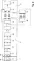
Eine erfindungsgemäße Anordnung besteht im Wesentlichen aus einem Stereo-Kamerasystem
Gemäß der Ausführung nach
Gemäß
BezugszeichenlisteLIST OF REFERENCE NUMBERS
- 11
- Kamerasystemcamera system
- 1111
- rechte Kameraright camera
- 1212
- linke Kameraleft camera
- 1313
- Hauptkameramain camera
- 1414
- erste Satellitenkamerafirst satellite camera
- 1515
- zweite Satellitenkamerasecond satellite camera
- 22
- BildkonvertierungseinrichtungImage conversion device
- 2020
- GrößenanpassungseinheitResizing unit
- 2121
- RektifizierungseinheitRektifizierungseinheit
- 2222
- FarbjustierungseinheitColor adjustment unit
- 2323
- Einheit zum Aufbau der StackstrukturUnit for building the stack structure
- 2424
- Einheit zur Optimierung der StackstrukturUnit for optimizing the stack structure
- 2525
- Einheit zur Projektion der Stackstruktur auf die gewünschte AnsichtUnit for projecting the stack structure onto the desired view
- 2626
- Einheit zur Ermittlung der TiefeUnit for determining the depth
- 33
- 3D-Bildwiedergabegerät3D image playback device
- 3030
- Einheit zur Rekonstruktion der StackstrukturUnit for the reconstruction of the stack structure
- 3131
- BildkombinationseinheitImage combining unit
- 3232
- 3D-Display3D display
- 3535
- Einheit zur Projektion der Stackstruktur auf die gewünschte AnsichtUnit for projecting the stack structure onto the desired view
Claims (6)
Translated fromGermanPriority Applications (10)
| Application Number | Priority Date | Filing Date | Title |
|---|---|---|---|
| DE102006055641ADE102006055641B4 (en) | 2006-11-22 | 2006-11-22 | Arrangement and method for recording and reproducing images of a scene and / or an object |
| US11/920,290US8330796B2 (en) | 2006-11-22 | 2007-04-27 | Arrangement and method for the recording and display of images of a scene and/or an object |
| EP07722343AEP2095625A1 (en) | 2006-11-22 | 2007-04-27 | Arrangement and method for capturing and reproducing images of a scene and/or an object |
| PCT/DE2007/000786WO2008064617A1 (en) | 2006-11-22 | 2007-04-27 | Arrangement and method for capturing and reproducing images of a scene and/or an object |
| EP14168468.8AEP2800350A3 (en) | 2006-11-22 | 2007-04-27 | Assembly and method for recording and reproducing images of a scene and/or an object |
| TW096128967ATWI347774B (en) | 2006-11-22 | 2007-08-07 | System and method for the recording and display of images of a scene and/or an object |
| EP07817759AEP2106657A2 (en) | 2006-11-22 | 2007-10-29 | Arrangement and method for capturing and displaying images of a scene and/or an object |
| US11/988,897US20100134599A1 (en) | 2006-11-22 | 2007-10-29 | Arrangement and method for the recording and display of images of a scene and/or an object |
| PCT/DE2007/001965WO2008061490A2 (en) | 2006-11-22 | 2007-10-29 | Arrangement and method for capturing and displaying images of a scene and/or an object |
| TW096143841ATW200841704A (en) | 2006-11-22 | 2007-11-20 | Arrangement and method for the recording and display of images of a scene and/or an object |
Applications Claiming Priority (1)
| Application Number | Priority Date | Filing Date | Title |
|---|---|---|---|
| DE102006055641ADE102006055641B4 (en) | 2006-11-22 | 2006-11-22 | Arrangement and method for recording and reproducing images of a scene and / or an object |
Publications (2)
| Publication Number | Publication Date |
|---|---|
| DE102006055641A1 DE102006055641A1 (en) | 2008-05-29 |
| DE102006055641B4true DE102006055641B4 (en) | 2013-01-31 |
Family
ID=38596678
Family Applications (1)
| Application Number | Title | Priority Date | Filing Date |
|---|---|---|---|
| DE102006055641AExpired - Fee RelatedDE102006055641B4 (en) | 2006-11-22 | 2006-11-22 | Arrangement and method for recording and reproducing images of a scene and / or an object |
Country Status (5)
| Country | Link |
|---|---|
| US (2) | US8330796B2 (en) |
| EP (3) | EP2095625A1 (en) |
| DE (1) | DE102006055641B4 (en) |
| TW (2) | TWI347774B (en) |
| WO (2) | WO2008064617A1 (en) |
Families Citing this family (51)
| Publication number | Priority date | Publication date | Assignee | Title |
|---|---|---|---|---|
| KR20080114169A (en)* | 2007-06-27 | 2008-12-31 | 삼성전자주식회사 | 3D image display method and imaging device using the same |
| KR101387366B1 (en)* | 2007-06-27 | 2014-04-21 | 삼성전자주식회사 | Multiview autostereoscopic display device and multiview autostereoscopic display method |
| KR20090055803A (en)* | 2007-11-29 | 2009-06-03 | 광주과학기술원 | Method and apparatus for generating multiview depth map and method for generating variance in multiview image |
| KR101420684B1 (en)* | 2008-02-13 | 2014-07-21 | 삼성전자주식회사 | Method and apparatus for matching color and depth images |
| DE102008023501B4 (en) | 2008-05-09 | 2011-04-14 | Visumotion Gmbh | Method and arrangement for the synchronous recording of at least two video data streams of different formats |
| US8866920B2 (en) | 2008-05-20 | 2014-10-21 | Pelican Imaging Corporation | Capturing and processing of images using monolithic camera array with heterogeneous imagers |
| US8184143B2 (en)* | 2008-06-27 | 2012-05-22 | Sony Mobile Communications Ab | Simulated reflective display |
| CA2691727C (en) | 2008-09-30 | 2016-10-04 | Panasonic Corporation | Recording medium, playback device, system lsi, playback method, glasses, and display device for 3d images |
| US20100135640A1 (en)* | 2008-12-03 | 2010-06-03 | Dell Products L.P. | System and Method for Storing and Displaying 3-D Video Content |
| US8780172B2 (en) | 2009-01-27 | 2014-07-15 | Telefonaktiebolaget L M Ericsson (Publ) | Depth and video co-processing |
| US8520020B2 (en)* | 2009-12-14 | 2013-08-27 | Canon Kabushiki Kaisha | Stereoscopic color management |
| KR101214536B1 (en)* | 2010-01-12 | 2013-01-10 | 삼성전자주식회사 | Method for performing out-focus using depth information and camera using the same |
| US8687044B2 (en)* | 2010-02-02 | 2014-04-01 | Microsoft Corporation | Depth camera compatibility |
| KR101647408B1 (en)* | 2010-02-03 | 2016-08-10 | 삼성전자주식회사 | Apparatus and method for image processing |
| DE102010020925B4 (en) | 2010-05-10 | 2014-02-27 | Faro Technologies, Inc. | Method for optically scanning and measuring an environment |
| US20120050495A1 (en)* | 2010-08-27 | 2012-03-01 | Xuemin Chen | Method and system for multi-view 3d video rendering |
| KR20120020627A (en)* | 2010-08-30 | 2012-03-08 | 삼성전자주식회사 | Apparatus and method for image processing using 3d image format |
| JP2012124704A (en)* | 2010-12-08 | 2012-06-28 | Sony Corp | Imaging apparatus and imaging method |
| KR101852811B1 (en)* | 2011-01-05 | 2018-04-27 | 엘지전자 주식회사 | Display device and method for controlling thereof |
| JP5058354B1 (en)* | 2011-04-19 | 2012-10-24 | 株式会社東芝 | Electronic device, display control method and program |
| CN104081414B (en) | 2011-09-28 | 2017-08-01 | Fotonation开曼有限公司 | Systems and methods for encoding and decoding light field image files |
| US9161010B2 (en) | 2011-12-01 | 2015-10-13 | Sony Corporation | System and method for generating robust depth maps utilizing a multi-resolution procedure |
| PL4296963T3 (en) | 2012-08-21 | 2025-04-28 | Adeia Imaging Llc | Method for depth detection in images captured using array cameras |
| EP4307659A1 (en)* | 2012-09-28 | 2024-01-17 | Adeia Imaging LLC | Generating images from light fields utilizing virtual viewpoints |
| DE102012109481A1 (en) | 2012-10-05 | 2014-04-10 | Faro Technologies, Inc. | Device for optically scanning and measuring an environment |
| US10067231B2 (en) | 2012-10-05 | 2018-09-04 | Faro Technologies, Inc. | Registration calculation of three-dimensional scanner data performed between scans based on measurements by two-dimensional scanner |
| US9386298B2 (en)* | 2012-11-08 | 2016-07-05 | Leap Motion, Inc. | Three-dimensional image sensors |
| JP6285958B2 (en) | 2013-01-15 | 2018-02-28 | モービルアイ ビジョン テクノロジーズ リミテッド | Stereo support with rolling shutter |
| US10484661B2 (en)* | 2013-08-06 | 2019-11-19 | Sony Interactive Entertainment Inc. | Three-dimensional image generating device, three-dimensional image generating method, program, and information storage medium |
| CN104567758B (en)* | 2013-10-29 | 2017-11-17 | 同方威视技术股份有限公司 | Stereo imaging system and its method |
| US9967538B2 (en) | 2013-11-04 | 2018-05-08 | Massachussetts Institute Of Technology | Reducing view transitions artifacts in automultiscopic displays |
| US9756316B2 (en)* | 2013-11-04 | 2017-09-05 | Massachusetts Institute Of Technology | Joint view expansion and filtering for automultiscopic 3D displays |
| TWI530909B (en) | 2013-12-31 | 2016-04-21 | 財團法人工業技術研究院 | System and method for image composition |
| CN104144335B (en)* | 2014-07-09 | 2017-02-01 | 歌尔科技有限公司 | A head-mounted visual device and video system |
| DE102014013678B3 (en) | 2014-09-10 | 2015-12-03 | Faro Technologies, Inc. | Method for optically sensing and measuring an environment with a handheld scanner and gesture control |
| US9693040B2 (en)* | 2014-09-10 | 2017-06-27 | Faro Technologies, Inc. | Method for optically measuring three-dimensional coordinates and calibration of a three-dimensional measuring device |
| US9671221B2 (en) | 2014-09-10 | 2017-06-06 | Faro Technologies, Inc. | Portable device for optically measuring three-dimensional coordinates |
| DE102014013677B4 (en) | 2014-09-10 | 2017-06-22 | Faro Technologies, Inc. | Method for optically scanning and measuring an environment with a handheld scanner and subdivided display |
| US9602811B2 (en) | 2014-09-10 | 2017-03-21 | Faro Technologies, Inc. | Method for optically measuring three-dimensional coordinates and controlling a three-dimensional measuring device |
| US20160173869A1 (en)* | 2014-12-15 | 2016-06-16 | Nokia Corporation | Multi-Camera System Consisting Of Variably Calibrated Cameras |
| US9621819B2 (en) | 2015-07-09 | 2017-04-11 | Chunghwa Picture Tubes, Ltd. | Electronic device and multimedia control method thereof |
| US10469821B2 (en)* | 2016-06-17 | 2019-11-05 | Altek Semiconductor Corp. | Stereo image generating method and electronic apparatus utilizing the method |
| CN107517369B (en)* | 2016-06-17 | 2019-08-02 | 聚晶半导体股份有限公司 | Stereoscopic image generation method and electronic device using same |
| JP6636963B2 (en)* | 2017-01-13 | 2020-01-29 | 株式会社東芝 | Image processing apparatus and image processing method |
| DE102017120956A1 (en) | 2017-09-11 | 2019-03-14 | Thomas Emde | Device for audio / visual recording and playback of images / films |
| US20200014909A1 (en) | 2018-07-03 | 2020-01-09 | Faro Technologies, Inc. | Handheld three dimensional scanner with autofocus or autoaperture |
| DE102019109147A1 (en)* | 2019-04-08 | 2020-10-08 | Carl Zeiss Jena Gmbh | PICTURE ACQUISITION SYSTEM AND METHOD OF CAPTURING PICTURES |
| US11039113B2 (en)* | 2019-09-30 | 2021-06-15 | Snap Inc. | Multi-dimensional rendering |
| CA3168799A1 (en)* | 2020-01-21 | 2021-07-29 | Proprio, Inc. | Methods and systems for augmenting depth data from a depth sensor, such as with data from a multiview camera system |
| US11503266B2 (en)* | 2020-03-06 | 2022-11-15 | Samsung Electronics Co., Ltd. | Super-resolution depth map generation for multi-camera or other environments |
| CN112995432B (en)* | 2021-02-05 | 2022-08-05 | 杭州叙简科技股份有限公司 | Depth image identification method based on 5G double recorders |
Citations (6)
| Publication number | Priority date | Publication date | Assignee | Title |
|---|---|---|---|---|
| WO2000013142A1 (en)* | 1998-08-28 | 2000-03-09 | Sarnoff Corporation | Method and apparatus for processing images |
| US6271876B1 (en)* | 1997-05-06 | 2001-08-07 | Eastman Kodak Company | Using two different capture media to make stereo images of a scene |
| KR20020032954A (en)* | 2000-10-28 | 2002-05-04 | 김춘호 | 3D Stereosc opic Multiview Video System and Manufacturing Method |
| US20030231179A1 (en)* | 2000-11-07 | 2003-12-18 | Norihisa Suzuki | Internet system for virtual telepresence |
| EP1418766A2 (en)* | 1998-08-28 | 2004-05-12 | Imax Corporation | Method and apparatus for processing images |
| DE102004061998A1 (en)* | 2004-12-23 | 2006-07-06 | Robert Bosch Gmbh | Stereo camera for a motor vehicle |
Family Cites Families (20)
| Publication number | Priority date | Publication date | Assignee | Title |
|---|---|---|---|---|
| JPH08201941A (en) | 1995-01-12 | 1996-08-09 | Texas Instr Inc <Ti> | Three-dimensional image forming method |
| CN1126377C (en)* | 1995-03-08 | 2003-10-29 | 皇家菲利浦电子有限公司 | Three-dimensional image display system |
| JP3096613B2 (en) | 1995-05-30 | 2000-10-10 | 三洋電機株式会社 | 3D display device |
| US6055012A (en)* | 1995-12-29 | 2000-04-25 | Lucent Technologies Inc. | Digital multi-view video compression with complexity and compatibility constraints |
| US6023291A (en)* | 1996-10-16 | 2000-02-08 | Space Systems/Loral, Inc. | Satellite camera attitude determination and image navigation by means of earth edge and landmark measurement |
| US6052124A (en)* | 1997-02-03 | 2000-04-18 | Yissum Research Development Company | System and method for directly estimating three-dimensional structure of objects in a scene and camera motion from three two-dimensional views of the scene |
| GB2343320B (en) | 1998-10-31 | 2003-03-26 | Ibm | Camera system for three dimentional images and video |
| JP2000321050A (en) | 1999-05-14 | 2000-11-24 | Minolta Co Ltd | Method and apparatus for acquiring three-dimensional data |
| DE60042475D1 (en)* | 1999-05-27 | 2009-08-13 | Ipg Electronics 503 Ltd | CODING OF A VIDEO SIGNAL WITH HIGH RESOLUTION CODING FOR INTERESTING REGIONS |
| US6198505B1 (en)* | 1999-07-19 | 2001-03-06 | Lockheed Martin Corp. | High resolution, high speed digital camera |
| CA2436596C (en)* | 2000-01-25 | 2005-10-25 | 4D-Vision Gmbh | Method and arrangement for the three-dimensional display |
| US20040104935A1 (en)* | 2001-01-26 | 2004-06-03 | Todd Williamson | Virtual reality immersion system |
| US7224382B2 (en)* | 2002-04-12 | 2007-05-29 | Image Masters, Inc. | Immersive imaging system |
| CA2386560A1 (en)* | 2002-05-15 | 2003-11-15 | Idelix Software Inc. | Controlling optical hardware and dynamic data viewing systems with detail-in-context viewing tools |
| JP4229398B2 (en) | 2003-03-28 | 2009-02-25 | 財団法人北九州産業学術推進機構 | Three-dimensional modeling program, three-dimensional modeling control program, three-dimensional modeling data transmission program, recording medium, and three-dimensional modeling method |
| US7532225B2 (en)* | 2003-09-18 | 2009-05-12 | Kabushiki Kaisha Toshiba | Three-dimensional image display device |
| US7525541B2 (en)* | 2004-04-05 | 2009-04-28 | Actuality Systems, Inc. | Data processing for three-dimensional displays |
| JPWO2005124687A1 (en) | 2004-06-16 | 2008-04-17 | 国立大学法人 東京大学 | Marker tracking method in optical motion capture system, optical motion capture method and system |
| US7468745B2 (en)* | 2004-12-17 | 2008-12-23 | Mitsubishi Electric Research Laboratories, Inc. | Multiview video decomposition and encoding |
| JP4488996B2 (en)* | 2005-09-29 | 2010-06-23 | 株式会社東芝 | Multi-view image creation apparatus, multi-view image creation method, and multi-view image creation program |
- 2006
- 2006-11-22DEDE102006055641Apatent/DE102006055641B4/ennot_activeExpired - Fee Related
- 2007
- 2007-04-27WOPCT/DE2007/000786patent/WO2008064617A1/enactiveApplication Filing
- 2007-04-27USUS11/920,290patent/US8330796B2/ennot_activeExpired - Fee Related
- 2007-04-27EPEP07722343Apatent/EP2095625A1/ennot_activeCeased
- 2007-04-27EPEP14168468.8Apatent/EP2800350A3/ennot_activeCeased
- 2007-08-07TWTW096128967Apatent/TWI347774B/ennot_activeIP Right Cessation
- 2007-10-29WOPCT/DE2007/001965patent/WO2008061490A2/enactiveApplication Filing
- 2007-10-29EPEP07817759Apatent/EP2106657A2/ennot_activeWithdrawn
- 2007-10-29USUS11/988,897patent/US20100134599A1/ennot_activeAbandoned
- 2007-11-20TWTW096143841Apatent/TW200841704A/enunknown
Patent Citations (6)
| Publication number | Priority date | Publication date | Assignee | Title |
|---|---|---|---|---|
| US6271876B1 (en)* | 1997-05-06 | 2001-08-07 | Eastman Kodak Company | Using two different capture media to make stereo images of a scene |
| WO2000013142A1 (en)* | 1998-08-28 | 2000-03-09 | Sarnoff Corporation | Method and apparatus for processing images |
| EP1418766A2 (en)* | 1998-08-28 | 2004-05-12 | Imax Corporation | Method and apparatus for processing images |
| KR20020032954A (en)* | 2000-10-28 | 2002-05-04 | 김춘호 | 3D Stereosc opic Multiview Video System and Manufacturing Method |
| US20030231179A1 (en)* | 2000-11-07 | 2003-12-18 | Norihisa Suzuki | Internet system for virtual telepresence |
| DE102004061998A1 (en)* | 2004-12-23 | 2006-07-06 | Robert Bosch Gmbh | Stereo camera for a motor vehicle |
Non-Patent Citations (1)
| Title |
|---|
| Kim, K.-T., et al., Synthesis of a high-resolution 3D-stereoscopic image pair from a high-resolution monoscopic image and a low-resolution depth map. In: Proceedings of the SPIE, Bd. 3295, Januar 1998, S. 76-86, ISSN: 0277-786X* |
Also Published As
| Publication number | Publication date |
|---|---|
| DE102006055641A1 (en) | 2008-05-29 |
| WO2008061490A3 (en) | 2008-08-28 |
| EP2800350A2 (en) | 2014-11-05 |
| US20100134599A1 (en) | 2010-06-03 |
| EP2800350A3 (en) | 2014-11-12 |
| US20090315982A1 (en) | 2009-12-24 |
| EP2095625A1 (en) | 2009-09-02 |
| WO2008064617A1 (en) | 2008-06-05 |
| TW200824427A (en) | 2008-06-01 |
| TW200841704A (en) | 2008-10-16 |
| EP2106657A2 (en) | 2009-10-07 |
| US8330796B2 (en) | 2012-12-11 |
| TWI347774B (en) | 2011-08-21 |
| WO2008061490A2 (en) | 2008-05-29 |
Similar Documents
| Publication | Publication Date | Title |
|---|---|---|
| DE102006055641B4 (en) | Arrangement and method for recording and reproducing images of a scene and / or an object | |
| DE69432692T2 (en) | Image processing device and method. | |
| DE69921240T2 (en) | Device for producing a stereoscopic image | |
| DE69428611T2 (en) | Autostereoscopic display device | |
| EP2027728B1 (en) | Method and device for the creation of pseudo-holographic images | |
| DE10016074B4 (en) | Method and device for generating 3D images | |
| EP0776576B1 (en) | Method and device for showing stereoscopic video images on a display | |
| WO2003046832A1 (en) | Generation of a stereo image sequence from a 2d image sequence | |
| EP3427474B1 (en) | Image processing method, image processing means and image processing device for generating images of a portion of a three-dimensional space | |
| DE69529260T2 (en) | Image processing apparatus and method | |
| DE102007037310A1 (en) | Network camera and control method for this | |
| WO2011103865A2 (en) | Method and autostereoscopic display for producing three-dimensional images | |
| EP2229784A1 (en) | Method and device for real-time multi-view production | |
| WO2009039800A1 (en) | Method for orienting a parallax barrier screen on a display screen | |
| WO2012097802A2 (en) | Method and device for stereo base extension of stereoscopic images and image sequences | |
| DE69009612T2 (en) | Method of treating and transmitting a sequence of stereoscopic television picture pairs through a channel containing an analog and a digital path. | |
| DE102005023461A1 (en) | monitoring device | |
| DE112012002679T5 (en) | Apparatus and method for encoding / decoding multi-view images | |
| WO2011032642A1 (en) | Method and device for generating partial views and/or a stereoscopic image master from a 2d-view for stereoscopic playback | |
| DE102019118510B4 (en) | Image processing method | |
| AT518256B1 (en) | GENERATING A PANORAMIC IMPOSITION FOR STEREOSCOPIC REPRODUCTION AND SUCH A PLAYBACK | |
| WO2006136181A1 (en) | Method and device for the stereoscopic recording of objects for a three-dimensional visualization | |
| DE102011107765B3 (en) | Method for smoothing transitions between scenes of a stereo movie as well as control or regulation of several 3D cameras | |
| EP3244369B1 (en) | Method for reproducing sequences of images and image processing unit and computer programme for the same | |
| WO1993011644A1 (en) | Method and device for reproducing three-dimensional images |
Legal Events
| Date | Code | Title | Description |
|---|---|---|---|
| OP8 | Request for examination as to paragraph 44 patent law | ||
| R016 | Response to examination communication | ||
| R018 | Grant decision by examination section/examining division | ||
| R020 | Patent grant now final | Effective date:20130501 | |
| R119 | Application deemed withdrawn, or ip right lapsed, due to non-payment of renewal fee | Effective date:20130601 |