DE102006028228B4 - Actuator for manual control of functions in a motor vehicle and electronic gear selector switch so - Google Patents
Actuator for manual control of functions in a motor vehicle and electronic gear selector switch soDownload PDFInfo
- Publication number
- DE102006028228B4 DE102006028228B4DE102006028228.0ADE102006028228ADE102006028228B4DE 102006028228 B4DE102006028228 B4DE 102006028228B4DE 102006028228 ADE102006028228 ADE 102006028228ADE 102006028228 B4DE102006028228 B4DE 102006028228B4
- Authority
- DE
- Germany
- Prior art keywords
- handle
- actuator
- pivoting
- transmission element
- rotary body
- Prior art date
- Legal status (The legal status is an assumption and is not a legal conclusion. Google has not performed a legal analysis and makes no representation as to the accuracy of the status listed.)
- Active
Links
- 230000005540biological transmissionEffects0.000claimsabstractdescription41
- 230000007935neutral effectEffects0.000claimsabstractdescription15
- 230000009471actionEffects0.000claimsabstractdescription5
- 241001422033ThestylusSpecies0.000claimsabstractdescription3
- 238000013016dampingMethods0.000claimsdescription8
- 239000000853adhesiveSubstances0.000description16
- 230000001070adhesive effectEffects0.000description16
- BGPVFRJUHWVFKM-UHFFFAOYSA-NN1=C2C=CC=CC2=[N+]([O-])C1(CC1)CCC21N=C1C=CC=CC1=[N+]2[O-]Chemical compoundN1=C2C=CC=CC2=[N+]([O-])C1(CC1)CCC21N=C1C=CC=CC1=[N+]2[O-]BGPVFRJUHWVFKM-UHFFFAOYSA-N0.000description13
- 238000013459approachMethods0.000description8
- 230000008859changeEffects0.000description2
- 238000013461designMethods0.000description2
- 230000004907fluxEffects0.000description2
- 230000009467reductionEffects0.000description2
- 230000003716rejuvenationEffects0.000description2
- 238000012549trainingMethods0.000description2
- 230000006835compressionEffects0.000description1
- 238000007906compressionMethods0.000description1
- 238000010276constructionMethods0.000description1
- 230000001419dependent effectEffects0.000description1
- 238000011161developmentMethods0.000description1
- 230000018109developmental processEffects0.000description1
- 230000007613environmental effectEffects0.000description1
- 238000009434installationMethods0.000description1
- 230000003993interactionEffects0.000description1
- 238000004519manufacturing processMethods0.000description1
- 229910052751metalInorganic materials0.000description1
- 239000002184metalSubstances0.000description1
- -1neodymium boron rare earthChemical class0.000description1
- 229910052761rare earth metalInorganic materials0.000description1
- 238000012546transferMethods0.000description1
Images


Classifications
- H—ELECTRICITY
- H01—ELECTRIC ELEMENTS
- H01H—ELECTRIC SWITCHES; RELAYS; SELECTORS; EMERGENCY PROTECTIVE DEVICES
- H01H25/00—Switches with compound movement of handle or other operating part
- H01H25/06—Operating part movable both angularly and rectilinearly, the rectilinear movement being along the axis of angular movement
- F—MECHANICAL ENGINEERING; LIGHTING; HEATING; WEAPONS; BLASTING
- F16—ENGINEERING ELEMENTS AND UNITS; GENERAL MEASURES FOR PRODUCING AND MAINTAINING EFFECTIVE FUNCTIONING OF MACHINES OR INSTALLATIONS; THERMAL INSULATION IN GENERAL
- F16H—GEARING
- F16H59/00—Control inputs to control units of change-speed- or reversing-gearings for conveying rotary motion
- F16H59/02—Selector apparatus
- F16H59/04—Ratio selector apparatus
- F16H59/044—Ratio selector apparatus consisting of electrical switches or sensors
- G—PHYSICS
- G05—CONTROLLING; REGULATING
- G05G—CONTROL DEVICES OR SYSTEMS INSOFAR AS CHARACTERISED BY MECHANICAL FEATURES ONLY
- G05G5/00—Means for preventing, limiting or returning the movements of parts of a control mechanism, e.g. locking controlling member
- G05G5/05—Means for returning or tending to return controlling members to an inoperative or neutral position, e.g. by providing return springs or resilient end-stops
- F—MECHANICAL ENGINEERING; LIGHTING; HEATING; WEAPONS; BLASTING
- F16—ENGINEERING ELEMENTS AND UNITS; GENERAL MEASURES FOR PRODUCING AND MAINTAINING EFFECTIVE FUNCTIONING OF MACHINES OR INSTALLATIONS; THERMAL INSULATION IN GENERAL
- F16H—GEARING
- F16H59/00—Control inputs to control units of change-speed- or reversing-gearings for conveying rotary motion
- F16H59/02—Selector apparatus
- F16H2059/026—Details or special features of the selector casing or lever support
- F16H2059/0269—Ball joints or spherical bearings for supporting the lever
- F—MECHANICAL ENGINEERING; LIGHTING; HEATING; WEAPONS; BLASTING
- F16—ENGINEERING ELEMENTS AND UNITS; GENERAL MEASURES FOR PRODUCING AND MAINTAINING EFFECTIVE FUNCTIONING OF MACHINES OR INSTALLATIONS; THERMAL INSULATION IN GENERAL
- F16H—GEARING
- F16H61/00—Control functions within control units of change-speed- or reversing-gearings for conveying rotary motion ; Control of exclusively fluid gearing, friction gearing, gearings with endless flexible members or other particular types of gearing
- F16H61/24—Providing feel, e.g. to enable selection
- F16H2061/243—Cams or detent arrays for guiding and providing feel
- F—MECHANICAL ENGINEERING; LIGHTING; HEATING; WEAPONS; BLASTING
- F16—ENGINEERING ELEMENTS AND UNITS; GENERAL MEASURES FOR PRODUCING AND MAINTAINING EFFECTIVE FUNCTIONING OF MACHINES OR INSTALLATIONS; THERMAL INSULATION IN GENERAL
- F16H—GEARING
- F16H61/00—Control functions within control units of change-speed- or reversing-gearings for conveying rotary motion ; Control of exclusively fluid gearing, friction gearing, gearings with endless flexible members or other particular types of gearing
- F16H61/24—Providing feel, e.g. to enable selection
- G—PHYSICS
- G05—CONTROLLING; REGULATING
- G05G—CONTROL DEVICES OR SYSTEMS INSOFAR AS CHARACTERISED BY MECHANICAL FEATURES ONLY
- G05G9/00—Manually-actuated control mechanisms provided with one single controlling member co-operating with two or more controlled members, e.g. selectively, simultaneously
- G05G9/02—Manually-actuated control mechanisms provided with one single controlling member co-operating with two or more controlled members, e.g. selectively, simultaneously the controlling member being movable in different independent ways, movement in each individual way actuating one controlled member only
- G05G9/04—Manually-actuated control mechanisms provided with one single controlling member co-operating with two or more controlled members, e.g. selectively, simultaneously the controlling member being movable in different independent ways, movement in each individual way actuating one controlled member only in which movement in two or more ways can occur simultaneously
- G05G9/047—Manually-actuated control mechanisms provided with one single controlling member co-operating with two or more controlled members, e.g. selectively, simultaneously the controlling member being movable in different independent ways, movement in each individual way actuating one controlled member only in which movement in two or more ways can occur simultaneously the controlling member being movable by hand about orthogonal axes, e.g. joysticks
- G05G2009/04703—Mounting of controlling member
- G05G2009/04707—Mounting of controlling member with ball joint
- G—PHYSICS
- G05—CONTROLLING; REGULATING
- G05G—CONTROL DEVICES OR SYSTEMS INSOFAR AS CHARACTERISED BY MECHANICAL FEATURES ONLY
- G05G9/00—Manually-actuated control mechanisms provided with one single controlling member co-operating with two or more controlled members, e.g. selectively, simultaneously
- G05G9/02—Manually-actuated control mechanisms provided with one single controlling member co-operating with two or more controlled members, e.g. selectively, simultaneously the controlling member being movable in different independent ways, movement in each individual way actuating one controlled member only
- G05G9/04—Manually-actuated control mechanisms provided with one single controlling member co-operating with two or more controlled members, e.g. selectively, simultaneously the controlling member being movable in different independent ways, movement in each individual way actuating one controlled member only in which movement in two or more ways can occur simultaneously
- G05G9/047—Manually-actuated control mechanisms provided with one single controlling member co-operating with two or more controlled members, e.g. selectively, simultaneously the controlling member being movable in different independent ways, movement in each individual way actuating one controlled member only in which movement in two or more ways can occur simultaneously the controlling member being movable by hand about orthogonal axes, e.g. joysticks
- G05G2009/04703—Mounting of controlling member
- G05G2009/04714—Mounting of controlling member with orthogonal axes
- G—PHYSICS
- G05—CONTROLLING; REGULATING
- G05G—CONTROL DEVICES OR SYSTEMS INSOFAR AS CHARACTERISED BY MECHANICAL FEATURES ONLY
- G05G9/00—Manually-actuated control mechanisms provided with one single controlling member co-operating with two or more controlled members, e.g. selectively, simultaneously
- G05G9/02—Manually-actuated control mechanisms provided with one single controlling member co-operating with two or more controlled members, e.g. selectively, simultaneously the controlling member being movable in different independent ways, movement in each individual way actuating one controlled member only
- G05G9/04—Manually-actuated control mechanisms provided with one single controlling member co-operating with two or more controlled members, e.g. selectively, simultaneously the controlling member being movable in different independent ways, movement in each individual way actuating one controlled member only in which movement in two or more ways can occur simultaneously
- G05G9/047—Manually-actuated control mechanisms provided with one single controlling member co-operating with two or more controlled members, e.g. selectively, simultaneously the controlling member being movable in different independent ways, movement in each individual way actuating one controlled member only in which movement in two or more ways can occur simultaneously the controlling member being movable by hand about orthogonal axes, e.g. joysticks
- G05G2009/0474—Manually-actuated control mechanisms provided with one single controlling member co-operating with two or more controlled members, e.g. selectively, simultaneously the controlling member being movable in different independent ways, movement in each individual way actuating one controlled member only in which movement in two or more ways can occur simultaneously the controlling member being movable by hand about orthogonal axes, e.g. joysticks characterised by means converting mechanical movement into electric signals
- G05G2009/04755—Magnetic sensor, e.g. hall generator, pick-up coil
- H—ELECTRICITY
- H01—ELECTRIC ELEMENTS
- H01H—ELECTRIC SWITCHES; RELAYS; SELECTORS; EMERGENCY PROTECTIVE DEVICES
- H01H2300/00—Orthogonal indexing scheme relating to electric switches, relays, selectors or emergency protective devices covered by H01H
- H01H2300/02—Application transmission, e.g. for sensing the position of a gear selector or automatic transmission
- H—ELECTRICITY
- H01—ELECTRIC ELEMENTS
- H01H—ELECTRIC SWITCHES; RELAYS; SELECTORS; EMERGENCY PROTECTIVE DEVICES
- H01H5/00—Snap-action arrangements, i.e. in which during a single opening operation or a single closing operation energy is first stored and then released to produce or assist the contact movement
- H01H5/02—Energy stored by the attraction or repulsion of magnetic parts
Landscapes
- Engineering & Computer Science (AREA)
- General Engineering & Computer Science (AREA)
- Physics & Mathematics (AREA)
- General Physics & Mathematics (AREA)
- Automation & Control Theory (AREA)
- Mechanical Engineering (AREA)
- Mechanical Control Devices (AREA)
Abstract
Translated fromGermanDescription
Translated fromGermanDie Erfindung geht aus von einem Stellglied nach dem Oberbegriff des Patentanspruchs 1.The invention is based on an actuator according to the preamble of
Stellglieder, wie in der Art eines Joystick- oder Cursor-Schalters ausgebildete elektrische und/oder elektronische Schalter, dienen zur Eingabe von Daten für ein elektrisches Gerät durch einen Benutzer. Beispielsweise werden solche Schalter für Autoradios, Navigationsgeräte, Bordcomputer oder auch zur manuellen Steuerung sonstiger Funktionen in Kraftfahrzeugen verwendet. Die Erfindung betrifft weiterhin einen elektronischer Gangwahlschalter mit dem erfindungsgemäßßen Stellglied, insbesonder für ein durch Shift by Wire gesteuertes Getriebe in einem Kraftfahrzeug.Actuators, such as electrical and / or electronic switches designed in the manner of a joystick or cursor switch, are used to input data for an electrical appliance by a user. For example, such switches are used for car radios, navigation devices, on-board computers or for the manual control of other functions in motor vehicles. The invention further relates to an electronic gear selector switch with the actuator according to the invention, in particular for a controlled by shift by wire transmission in a motor vehicle.
Ein derartiges als elektrischer Schalter ausgebildetes Stellglied ist aus der
In der
Weiter ist aus der
Schließlich sind in der
Der Erfindung liegt die Aufgabe zugrunde, das Stellglied im Hinblick auf die Betätigung des Moduls, gegebenenfalls auch auf die Anordnung von Modulen weiterzubilden, insbesondere indem die Handhabe zum Steuern von mehreren, beispielsweise vier, funktional und gegenständlich voneinander getrennten Modulen geeignet ist. Bevorzugterweise soll die Anordnung der Module derart ausgestaltet werden, daß die Ergonomie für das mit hoher Funktionalität versehene Stellglied gesteigert ist, wobei das Stellglied insbesondere jedoch mit kleinem Bauraum auskommen soll.The invention has for its object to further develop the actuator with respect to the actuation of the module, optionally also to the arrangement of modules, in particular by the handle for controlling a plurality, for example four, functionally and representationally separate modules is suitable. Preferably, the arrangement of the modules is to be designed such that the ergonomics of the actuator provided with high functionality is increased, the actuator but in particular to get along with a small space.
Diese Aufgabe wird bei einem gattungsgemäßen Stellglied durch die kennzeichnenden Merkmale des Anspruchs 1 gelöst.This object is achieved in a generic actuator by the characterizing features of
Beim erfindungsgemäßen Stellglied wirkt mit der Handhabe eine am abstehenden Ansatz angeordnete Rückstellfeder zur Rückstellung in die neutrale Stellung zusammen. Vorteilhafterweise bietet dadurch das Stellglied dem Benutzer eine ergonomische Handhabung und ist dennoch sehr kleinbauend sowie kompakt ausgestaltet. Weiter wird so eine exakte Bewegung für die Handhabe gewährleistet und die Ergonomie für den Benutzer gesteigert. Bevorzugterweise besitzt die Handhabe wenigstens zwei Schwenkstellungen, insbesondere jedoch vier Schwenkstellungen, so daß vier Module unabhängig voneinander mittels vier Übertragungselementen in der jeweiligen Schwenkstellung betätigbar sind. Weitere Ausgestaltungen der Erfindung sind Gegenstand der Unteransprüche.When the actuator according to the invention acts on the handle arranged on a protruding approach restoring spring for returning to the neutral position together. Advantageously, this provides the actuator to the user an ergonomic handling and is still designed very compact and compact. Furthermore, this guarantees an exact movement for the handle and increases the ergonomics for the user. Preferably, the handle has at least two pivot positions, but in particular four pivot positions, so that four modules can be actuated independently by means of four transmission elements in the respective pivot position. Further embodiments of the invention are the subject of the dependent claims.
Zur weiteren Kompaktifizierung der Ausgestaltung des Stellglieds ist am Drehkörper ein Stift, insbesondere mit einem runden Querschnitt angebracht. Der Stift durchgreift eine Aussparung in der Lagerschale und greift, beispielsweise mittels eines verjüngten Endes, in eine Bohrung am Übertragungselement ein. Das Übertragungselement ist in einer Nut linear geführt. Die Bohrung ist mit einer Fase, einem Radius o. dgl. versehen, wobei die Fase, der Radius o. dgl. größer als der maximale Dreh- bzw. Verschwenkwinkel des Drehkörpers ist, wodurch eine Behinderung der Verschwenkung ausgeschlossen ist.For further compactification of the configuration of the actuator, a pin, in particular with a round cross section, is mounted on the rotating body. The pin passes through a recess in the bearing shell and engages, for example by means of a tapered end, in a bore on the transmission element. The transmission element is linearly guided in a groove. The bore is provided with a chamfer, a radius o. The like., Wherein the chamfer, the radius o. The like. Is greater than the maximum rotational or pivoting angle of the rotary body, whereby a hindrance of the pivoting is excluded.
Das Übertragungselement besteht aus Kunststoff und ist in der Nut spielarm geführt. Zur Geräuschreduzierung für das Zurückstellen in die neutrale Stellung wirkt ein Dämpfungselement mit der Handhabe zusammen. Das Dämpfungselement ist beispielsweise am abstehenden Ansatz angebracht.The transmission element consists of plastic and is guided in the groove play. to Noise reduction for returning to the neutral position, a damping element cooperates with the handle together. The damping element is attached, for example, on the projecting approach.
Bei dem Modul kann es sich beispielsweise um ein Schaltelement, Sensorelement, Signalelement o. dgl. zur Erzeugung eines Schaltsigals handeln. In diesem Fall besteht das Sensorelement bevorzugterweise aus wenigstens einer magnetisierten Codeplatte sowie wenigstens einem zugeordneten Hallsensor. Zweckmäßigerweise ist die Codeplatte am Übertragungselement befestigt. Ein derartiges Sensorelement ist der Linearbewegung des Übertragungselements besonders angepaßt.The module may, for example, be a switching element, sensor element, signal element or the like for generating a switching signal. In this case, the sensor element preferably consists of at least one magnetized code plate and at least one associated Hall sensor. Conveniently, the code plate is attached to the transmission element. Such a sensor element is particularly adapted to the linear movement of the transmission element.
In einer weiteren Ausgestaltung handelt es sich bei dem Modul um ein Riegelelement. Dadurch ist die Handhabe in der Schwenkstellung verriegelbar. Das Riegelelement ist zweckmäßigerweise am Übertragungselement befestigt und/oder wirkt mit dem Übertragungselement zusammen.In a further embodiment, the module is a locking element. As a result, the handle can be locked in the pivoting position. The locking element is expediently attached to the transmission element and / or cooperates with the transmission element.
Bei wiederum einer anderen Ausführung handelt es sich bei dem Modul um ein Rastelement. Dadurch ist die Handhabe in der Schwenkstellung verrastbar. Das Rastelement ist zweckmäßigerweise am Übertragungselement befestigt und/oder wirkt mit dem Übertragungselement zusammen.In yet another embodiment, the module is a detent element. As a result, the handle can be locked in the pivoting position. The locking element is suitably attached to the transmission element and / or cooperates with the transmission element.
Das erfindungsgemäße Stellglied eignet sich besonders als Betätigungsorgan für einen elektrischen und/oder elektronischen Schalter, der insbesondere in der Art eines Joystick- oder Cursor-Schalters ausgestaltet ist. Beispielsweise kann ein solcher elektrischer Schalter als Gangwahlschalter für ein Kraftfahrzeug Verwendung finden.The actuator according to the invention is particularly suitable as an actuator for an electrical and / or electronic switch, which is designed in particular in the manner of a joystick or cursor switch. For example, such an electrical switch can be used as a gear selector switch for a motor vehicle.
Zusammenfassend ist eine besonders vorteilhafte Ausgestaltung für das Stellglied darin zu sehen, daß das Stellglied durch einen in mehreren Richtungen beweglichen Drehkörper gelagert ist. Durch Aussparungen in der Lagerschale bewegen vier Schaltarme verschiedene Module im Schalter. Ein weiteres Modul ist als Kulisse ausgelegt, in das ein fünfter Schaltarm als Taststift eingreift. Mit ihr wird das Stellglied geführt und die Drehhaptik erzeugt. Durch die Abstützung der als Druckfeder ausgebildeten Rückstellfeder an der Lagerschale, sowie des in Wirkrichtung der Feder frei am Ansatz gelagerten Taststiftes, entsteht in der Lagerstelle keine unerwünschte Reibung. Bei Rotation des Stellgliedes um eine Achse verändern mindestens drei Schaltarme ihre Lage. Bei Rotation des Stellgliedes um zwei Drehachsen verändern alle fünf Schaltarme ihre Lage. Durch besonders ausgeformte Aufnahmen an den Modulen kann die mehrfach rotatorische Bewegung des Schaltarms in eine Linearbewegung geändert werden. Auf diese Weise können lineargeführte Module, beispielsweise vier solcher Module, angesteuert werden. Die Position der Module im Schalter kann bei gleichen Schaltarmen nach Wunsch verändert werden.In summary, a particularly advantageous embodiment for the actuator is to be seen in that the actuator is mounted by a rotating body movable in several directions. Through recesses in the bearing shell four switching arms move various modules in the switch. Another module is designed as a backdrop in which engages a fifth switching arm as a stylus. With her the actuator is guided and generates the rotational feel. By supporting the return spring formed as a compression spring on the bearing shell, as well as in the effective direction of the spring freely mounted on the approach stylus, arises in the bearing no unwanted friction. Upon rotation of the actuator about an axis at least three switching arms change their position. When the actuator rotates about two axes of rotation, all five switching arms change their position. Due to specially shaped receptacles on the modules, the multiple rotatory movement of the switching arm can be changed into a linear movement. In this way linearly controlled modules, for example four such modules, can be controlled. The position of the modules in the switch can be changed as desired with the same switch arms.
Eine solche Ausbildung realisiert nachfolgende Randbedingungen. Zum einen kann bei Rotation des Stellgliedes um die Drehachse die Winkelstellung mehrerer Drehachsen erkannt werden. Zum anderen ist bei Rotation des Stellgliedes um die Drehachse eine beliebige Drehhaptik erzeugbar. Desweiteren sind je nach Ausführung funktional und gegenständlich getrennte Module steuerbar. Dabei ist die Position der Module im Schalter veränderbar. Schließlich soll in der Lagerstelle keine bzw. nur eine geringe Reibung herrschen.Such a training realizes the following boundary conditions. On the one hand, upon rotation of the actuator about the axis of rotation, the angular position of a plurality of axes of rotation can be detected. On the other hand, any rotational haptics can be generated on rotation of the actuator about the axis of rotation. Furthermore, depending on the design, functionally and objectively separate modules can be controlled. The position of the modules in the switch can be changed. Finally, there should be no or only a slight friction in the bearing.
Die mit der Erfindung erzielten Vorteile bestehen insbesondere darin, daß das Stellglied trotz hoher Funktionalität mit geringem Platzbedarf auskommt. Damit ist das Stellglied für enge Bauräume, wie sie im Armaturenbrett, der Mittelkonsole, der Armlehne o. dgl. im Kraftfahrzeug gegeben sind, geeignet. Weiter ist das Stellglied fehlerunanfällig und besitzt eine hohe Lebensdauer. Das erfindungsgemäße Stellglied läßt sich somit vorteilhaft in rauhen Umgebungsbedingungen, beispielsweise in Kraftfahrzeugen, einsetzen. Außerdem weist das Stellglied eine gute Haptik auf. Trotz hoher Funktionalität ist das Stellglied einfach zu bedienen, wobei Fehlbedienungen weitgehend ausgeschlossen sind. Außerdem ist das Stellglied kostengünstig herzustellen.The advantages achieved by the invention are in particular that the actuator manages despite high functionality with little space. Thus, the actuator for tight spaces, such as those in the dashboard, the center console, the armrest o. The like. Are given in the motor vehicle, suitable. Furthermore, the actuator is error-prone and has a long service life. The actuator according to the invention can thus be used advantageously in harsh environmental conditions, for example in motor vehicles. In addition, the actuator has a good feel. Despite high functionality, the actuator is easy to use, with incorrect operation are largely excluded. In addition, the actuator is inexpensive to manufacture.
Weitere Vorteile sind darüberhinaus in Folgendem zu sehen:
- - Das System erfordert lediglich eine geringe Teilezahl.
- - Es handelt sich um einen platzsparenden Aufbau.
- - Das Stellglied besitzt eine reibungsarme Lagerung.
- - Es erfolgt eine Spielreduzierung durch direkte Übertragung der Bewegungen.
- - The system requires only a small number of parts.
- - It is a space-saving construction.
- - The actuator has a low-friction bearing.
- - There is a game reduction by direct transfer of the movements.
Ein Ausführungsbeispiel der Erfindung mit verschiedenen Weiterbildungen und Ausgestaltungen ist in den Zeichnungen dargestellt und wird im folgenden näher beschrieben. Es zeigen
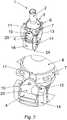
1 ein Stellglied, wobei die Handhabe in neutraler Stellung befindlich ist,2 das Stellglied, wobei die Handhabe in Schwenkstellung befindlich ist,3 schematisch die Handhabe mit dem Rastelement,4 das Stellglied in Seitenansicht und Draufsicht,5 das Stellglied in perspektivischer Ansicht mit vergrößertem Detailausschnitt,6 das Stellglied in perspektivischer Ansicht mit vergrößertem weiteren Detailausschnitt,7 das Stellglied in perspektivischer Ansicht mit vergrößertem nochmaligen weiteren Detailausschnitt,8 das Stellglied in einer weiteren perspektivischen Ansicht,9 einen elektrischen Schalter, der ein Stellglied wie in1 aufweist, und10 schematisch das Stellglied zur Steuerung von Modulen.
1 an actuator, wherein the handle is in a neutral position,2 the actuator, wherein the handle is in pivoting position,3 schematically the handle with the locking element,4 the actuator in side view and top view,5 the actuator in perspective view with enlarged detail,6 the actuator in perspective view with enlarged detail detail,7 the actuator in perspective view with enlarged further detail detail,8th the actuator in a further perspective view,9 an electrical switch, which is an actuator as in1 has, and10 schematically the actuator for controlling modules.
In
Das Rastelement
Das Verschwenkmittel
Wie in
Wie bereits erwähnt, weist die Handhabe
Zur Erzeugung einer großen Rastkraft kann der Permanentmagnet
Wie in
Wie bereits erwähnt, kann das Stellglied
Das Stellglied
Wie bereits erläutert, besitzt das Stellglied
Bei dem Modul kann es sich beispielsweise um das bereits erwähnte Schaltelement, Sensorelement
Ein derartiges Stellglied
BezugszeichenlisteLIST OF REFERENCE NUMBERS
- 1:1:
- Stellglied / BetätigungsorganActuator / actuator
- 2:2:
- Handhabehandle
- 3:3:
- VerschwenkmittelVerschwenkmittel
- 4:4:
- Haftkörperadhesive body
- 5:5:
- Permanentmagnetpermanent magnet
- 6:6:
- Drehkörperrotating body
- 7:7:
- Lagerschalebearing shell
- 8:8th:
- Kulissescenery
- 9:9:
- RückstellfederReturn spring
- 10:10:
- Stiftpen
- 11:11:
- Aussparung (in Lagerschale)Recess (in bearing shell)
- 12:12:
- Bohrung (im Haftkörper)Bore (in the adhesive body)
- 13:13:
- Nutgroove
- 14:14:
- Halterungbracket
- 15:15:
- Fasechamfer
- 16:16:
- Elektromagnetelectromagnet
- 17:17:
- SpuleKitchen sink
- 18:18:
- Ankeranchor
- 19:19:
- Magnet-FlußleitstückMagnetic flux guide
- 20:20:
- Träger / ÜbertragungselementCarrier / transmission element
- 21:21:
- Dämpfungselementdamping element
- 22:22:
- Sensorelementsensor element
- 23:23:
- Codeplattecode plate
- 24:24:
- Rastelement / Modul / RiegelelementLocking element / module / locking element
- 25:25:
- Ansatzapproach
- 26:26:
- Taststiftfeeler
- 27:27:
- Leiterplattecircuit board
- 28,29:28.29:
- Verjüngung (am Stift) / verjüngtes EndeRejuvenation (at the pin) / tapered end
Claims (16)
Translated fromGermanPriority Applications (1)
| Application Number | Priority Date | Filing Date | Title |
|---|---|---|---|
| DE102006028228.0ADE102006028228B4 (en) | 2005-06-24 | 2006-06-20 | Actuator for manual control of functions in a motor vehicle and electronic gear selector switch so |
Applications Claiming Priority (3)
| Application Number | Priority Date | Filing Date | Title |
|---|---|---|---|
| DE102005029394.8 | 2005-06-24 | ||
| DE102005029394 | 2005-06-24 | ||
| DE102006028228.0ADE102006028228B4 (en) | 2005-06-24 | 2006-06-20 | Actuator for manual control of functions in a motor vehicle and electronic gear selector switch so |
Publications (2)
| Publication Number | Publication Date |
|---|---|
| DE102006028228A1 DE102006028228A1 (en) | 2006-12-28 |
| DE102006028228B4true DE102006028228B4 (en) | 2019-09-26 |
Family
ID=37513764
Family Applications (1)
| Application Number | Title | Priority Date | Filing Date |
|---|---|---|---|
| DE102006028228.0AActiveDE102006028228B4 (en) | 2005-06-24 | 2006-06-20 | Actuator for manual control of functions in a motor vehicle and electronic gear selector switch so |
Country Status (1)
| Country | Link |
|---|---|
| DE (1) | DE102006028228B4 (en) |
Families Citing this family (15)
| Publication number | Priority date | Publication date | Assignee | Title |
|---|---|---|---|---|
| CA2728981C (en)* | 2007-06-21 | 2015-11-24 | Terry Peterson | Hall effect methods and systems |
| ES2423308T3 (en) | 2009-02-17 | 2013-09-19 | Kwc Ag | Sanitary tap with a joint |
| EP2218840B1 (en) | 2009-02-17 | 2012-10-10 | Kwc Ag | Sanitary fitting with joystick control |
| DE102010064007A1 (en) | 2010-12-23 | 2012-06-28 | Bayerische Motoren Werke Aktiengesellschaft | Switching device with switching state detection |
| DE102011079863A1 (en) | 2011-07-26 | 2013-01-31 | Continental Automotive Gmbh | operating device |
| DE102012104098B4 (en) | 2012-05-10 | 2015-08-27 | Elobau Gmbh & Co. Kg | Lockable joystick |
| DE102014223046A1 (en)* | 2014-11-12 | 2016-05-12 | Zf Friedrichshafen Ag | Coupling device for a shift lever, shift lever device and method for producing a coupling device |
| DE102015102317A1 (en) | 2015-02-18 | 2016-08-18 | Elobau Gmbh & Co. Kg | joystick |
| JP6452155B2 (en)* | 2015-07-06 | 2019-01-16 | アルプス電気株式会社 | Multi-directional operating device and vehicle shift device using the multi-directional operating device |
| JP6449200B2 (en) | 2016-07-28 | 2019-01-09 | 株式会社東海理化電機製作所 | Shift device |
| JP6391632B2 (en)* | 2016-07-28 | 2018-09-19 | 株式会社東海理化電機製作所 | Shift device |
| DE102017110472B4 (en)* | 2017-05-15 | 2018-11-22 | Elobau Gmbh & Co. Kg | Joystick for controlling vehicle, machine or plant functions |
| DE102017114593B4 (en) | 2017-06-29 | 2024-06-27 | Küster Holding GmbH | Device and method for selecting gears in motor vehicles |
| DE102017114591A1 (en) | 2017-06-29 | 2019-01-03 | Küster Holding GmbH | Device and method for selecting driving steps in motor vehicles |
| CN119742192B (en)* | 2025-03-06 | 2025-04-25 | 宝鸡恒盛电气科技有限公司 | A damping adjustable insulating pull rod |
Citations (6)
| Publication number | Priority date | Publication date | Assignee | Title |
|---|---|---|---|---|
| US3784746A (en) | 1971-07-06 | 1974-01-08 | R Hess | Single actuator for effecting multiple controls |
| US4459440A (en) | 1983-03-21 | 1984-07-10 | Wico Corporation | Joystick and switch assembly therefor |
| US4827982A (en) | 1986-12-22 | 1989-05-09 | Kayaba Industry Co., Ltd. | Detent mechanism for pressure control valve |
| US5491462A (en) | 1994-02-22 | 1996-02-13 | Wico Corporation | Joystick controller |
| US6181327B1 (en) | 1998-08-04 | 2001-01-30 | Primax Electronics Ltd | Computer joystick |
| DE10231015A1 (en) | 2002-07-09 | 2004-03-04 | ZF Lemförder Metallwaren AG | Motion translator for an isodistant switching sensor system |
- 2006
- 2006-06-20DEDE102006028228.0Apatent/DE102006028228B4/enactiveActive
Patent Citations (6)
| Publication number | Priority date | Publication date | Assignee | Title |
|---|---|---|---|---|
| US3784746A (en) | 1971-07-06 | 1974-01-08 | R Hess | Single actuator for effecting multiple controls |
| US4459440A (en) | 1983-03-21 | 1984-07-10 | Wico Corporation | Joystick and switch assembly therefor |
| US4827982A (en) | 1986-12-22 | 1989-05-09 | Kayaba Industry Co., Ltd. | Detent mechanism for pressure control valve |
| US5491462A (en) | 1994-02-22 | 1996-02-13 | Wico Corporation | Joystick controller |
| US6181327B1 (en) | 1998-08-04 | 2001-01-30 | Primax Electronics Ltd | Computer joystick |
| DE10231015A1 (en) | 2002-07-09 | 2004-03-04 | ZF Lemförder Metallwaren AG | Motion translator for an isodistant switching sensor system |
Also Published As
| Publication number | Publication date |
|---|---|
| DE102006028228A1 (en) | 2006-12-28 |
Similar Documents
| Publication | Publication Date | Title |
|---|---|---|
| DE102006028228B4 (en) | Actuator for manual control of functions in a motor vehicle and electronic gear selector switch so | |
| EP1736846B1 (en) | Actuator, in particular of the electric switch type | |
| EP0754886B1 (en) | Control lever assembly | |
| DE10241869B4 (en) | Electric switch | |
| EP0893750A1 (en) | Dispositif de commande multifonction | |
| DE102009013441A1 (en) | Electric switch | |
| DE10304804B4 (en) | Electric multi-directional switch | |
| EP1652201A2 (en) | Electric switch | |
| DE102008060256A1 (en) | Control element for e.g. carrying out data entry on or in vehicle component, has force generating unit generating resistance force during tilting of lever, where unit is adjustable for adjusting torque acting on lever | |
| EP2856485B1 (en) | Operating device, particularly of an electrical switch type | |
| DE102011005370A1 (en) | Lever actuator | |
| EP3074836A2 (en) | Actuator, in particular for a motor vehicle | |
| DE102015008517A1 (en) | Actuator, in particular for a motor vehicle | |
| EP1215556B1 (en) | Electric switch | |
| EP1715401B1 (en) | Electric switch | |
| EP1621954B1 (en) | Electrical joystick | |
| DE102012017122B4 (en) | Electrical switch | |
| DE102014017480A1 (en) | Actuator, in particular for a motor vehicle | |
| DE102006028227A1 (en) | Actuator e.g. electronic gear selection switch, for motor vehicle, has handle and rotating unit working together, where break force acting on handle in rotatable position is produced by magnetic strength | |
| EP3914988B1 (en) | Actuator, in particular for a motor vehicle | |
| DE102004032335B4 (en) | Electric switch and switch arrangement | |
| DE102004035078B4 (en) | Electric switch and motor vehicle with a steering wheel, on which such an electrical switch is arranged | |
| DE10105177A1 (en) | Vehicle onboard computer for use with navigation, communications, control, etc. has an improved operating device for cursor movement and command entry that is simple to use and ergonomic | |
| DE102004032337B4 (en) | Electric switch and steering wheel equipped therewith | |
| DE102010023171A1 (en) | Electric switch, particularly in form of joystick switch, cursor switch, multifunctional switch or rotary switch, has actuator, which acts together with deflecting unit |
Legal Events
| Date | Code | Title | Description |
|---|---|---|---|
| R012 | Request for examination validly filed | Effective date:20130607 | |
| R079 | Amendment of ipc main class | Free format text:PREVIOUS MAIN CLASS: H01H0025060000 Ipc:H01H0025040000 | |
| R016 | Response to examination communication | ||
| R018 | Grant decision by examination section/examining division | ||
| R020 | Patent grant now final |