DE10157647C5 - Method for producing three-dimensional workpieces in a laser material processing system or a stereolithography system - Google Patents
Method for producing three-dimensional workpieces in a laser material processing system or a stereolithography systemDownload PDFInfo
- Publication number
- DE10157647C5 DE10157647C5DE10157647ADE10157647ADE10157647C5DE 10157647 C5DE10157647 C5DE 10157647C5DE 10157647 ADE10157647 ADE 10157647ADE 10157647 ADE10157647 ADE 10157647ADE 10157647 C5DE10157647 C5DE 10157647C5
- Authority
- DE
- Germany
- Prior art keywords
- laser
- workpiece
- energy density
- layers
- layer
- Prior art date
- Legal status (The legal status is an assumption and is not a legal conclusion. Google has not performed a legal analysis and makes no representation as to the accuracy of the status listed.)
- Expired - Lifetime
Links
- 239000000463materialSubstances0.000titleclaimsabstractdescription58
- 238000004519manufacturing processMethods0.000titleclaimsabstractdescription14
- 238000000034methodMethods0.000claimsabstractdescription36
- 238000002844meltingMethods0.000claimsabstractdescription19
- 230000008018meltingEffects0.000claimsabstractdescription19
- 230000005855radiationEffects0.000claimsabstractdescription13
- 238000005245sinteringMethods0.000claimsabstractdescription13
- 239000002184metalSubstances0.000claimsabstractdescription10
- 235000011837pastiesNutrition0.000claimsabstractdescription7
- 238000002679ablationMethods0.000claimsdescription7
- 239000000758substrateSubstances0.000claimsdescription4
- 238000001816coolingMethods0.000claimsdescription3
- 238000000280densificationMethods0.000claims1
- 239000010410layerSubstances0.000description49
- 238000009499grossingMethods0.000description12
- 239000000843powderSubstances0.000description9
- 239000002245particleSubstances0.000description5
- 229910000831SteelInorganic materials0.000description4
- 239000010959steelSubstances0.000description4
- 238000005259measurementMethods0.000description3
- 238000010276constructionMethods0.000description2
- 238000009770conventional sinteringMethods0.000description2
- 230000001419dependent effectEffects0.000description2
- 230000035515penetrationEffects0.000description2
- 239000002344surface layerSubstances0.000description2
- 230000008646thermal stressEffects0.000description2
- 239000013598vectorSubstances0.000description2
- 238000000149argon plasma sinteringMethods0.000description1
- 239000011248coating agentSubstances0.000description1
- 238000000576coating methodMethods0.000description1
- 239000000470constituentSubstances0.000description1
- 238000011161developmentMethods0.000description1
- 230000018109developmental processEffects0.000description1
- 238000005516engineering processMethods0.000description1
- 230000003628erosive effectEffects0.000description1
- 230000004927fusionEffects0.000description1
- 238000002156mixingMethods0.000description1
- 239000012768molten materialSubstances0.000description1
- 238000000465mouldingMethods0.000description1
- 230000003287optical effectEffects0.000description1
- 239000012254powdered materialSubstances0.000description1
- 230000003252repetitive effectEffects0.000description1
- 230000003595spectral effectEffects0.000description1
- 239000007858starting materialSubstances0.000description1
- 230000003746surface roughnessEffects0.000description1
- 230000007704transitionEffects0.000description1
Images


Classifications
- B—PERFORMING OPERATIONS; TRANSPORTING
- B22—CASTING; POWDER METALLURGY
- B22F—WORKING METALLIC POWDER; MANUFACTURE OF ARTICLES FROM METALLIC POWDER; MAKING METALLIC POWDER; APPARATUS OR DEVICES SPECIALLY ADAPTED FOR METALLIC POWDER
- B22F3/00—Manufacture of workpieces or articles from metallic powder characterised by the manner of compacting or sintering; Apparatus specially adapted therefor ; Presses and furnaces
- B22F3/24—After-treatment of workpieces or articles
- B—PERFORMING OPERATIONS; TRANSPORTING
- B22—CASTING; POWDER METALLURGY
- B22F—WORKING METALLIC POWDER; MANUFACTURE OF ARTICLES FROM METALLIC POWDER; MAKING METALLIC POWDER; APPARATUS OR DEVICES SPECIALLY ADAPTED FOR METALLIC POWDER
- B22F10/00—Additive manufacturing of workpieces or articles from metallic powder
- B22F10/20—Direct sintering or melting
- B22F10/28—Powder bed fusion, e.g. selective laser melting [SLM] or electron beam melting [EBM]
- B—PERFORMING OPERATIONS; TRANSPORTING
- B22—CASTING; POWDER METALLURGY
- B22F—WORKING METALLIC POWDER; MANUFACTURE OF ARTICLES FROM METALLIC POWDER; MAKING METALLIC POWDER; APPARATUS OR DEVICES SPECIALLY ADAPTED FOR METALLIC POWDER
- B22F10/00—Additive manufacturing of workpieces or articles from metallic powder
- B22F10/30—Process control
- B22F10/36—Process control of energy beam parameters
- B—PERFORMING OPERATIONS; TRANSPORTING
- B22—CASTING; POWDER METALLURGY
- B22F—WORKING METALLIC POWDER; MANUFACTURE OF ARTICLES FROM METALLIC POWDER; MAKING METALLIC POWDER; APPARATUS OR DEVICES SPECIALLY ADAPTED FOR METALLIC POWDER
- B22F10/00—Additive manufacturing of workpieces or articles from metallic powder
- B22F10/50—Treatment of workpieces or articles during build-up, e.g. treatments applied to fused layers during build-up
- B—PERFORMING OPERATIONS; TRANSPORTING
- B22—CASTING; POWDER METALLURGY
- B22F—WORKING METALLIC POWDER; MANUFACTURE OF ARTICLES FROM METALLIC POWDER; MAKING METALLIC POWDER; APPARATUS OR DEVICES SPECIALLY ADAPTED FOR METALLIC POWDER
- B22F10/00—Additive manufacturing of workpieces or articles from metallic powder
- B22F10/60—Treatment of workpieces or articles after build-up
- B22F10/66—Treatment of workpieces or articles after build-up by mechanical means
- B—PERFORMING OPERATIONS; TRANSPORTING
- B22—CASTING; POWDER METALLURGY
- B22F—WORKING METALLIC POWDER; MANUFACTURE OF ARTICLES FROM METALLIC POWDER; MAKING METALLIC POWDER; APPARATUS OR DEVICES SPECIALLY ADAPTED FOR METALLIC POWDER
- B22F12/00—Apparatus or devices specially adapted for additive manufacturing; Auxiliary means for additive manufacturing; Combinations of additive manufacturing apparatus or devices with other processing apparatus or devices
- B22F12/40—Radiation means
- B22F12/41—Radiation means characterised by the type, e.g. laser or electron beam
- B—PERFORMING OPERATIONS; TRANSPORTING
- B22—CASTING; POWDER METALLURGY
- B22F—WORKING METALLIC POWDER; MANUFACTURE OF ARTICLES FROM METALLIC POWDER; MAKING METALLIC POWDER; APPARATUS OR DEVICES SPECIALLY ADAPTED FOR METALLIC POWDER
- B22F12/00—Apparatus or devices specially adapted for additive manufacturing; Auxiliary means for additive manufacturing; Combinations of additive manufacturing apparatus or devices with other processing apparatus or devices
- B22F12/40—Radiation means
- B22F12/44—Radiation means characterised by the configuration of the radiation means
- B—PERFORMING OPERATIONS; TRANSPORTING
- B29—WORKING OF PLASTICS; WORKING OF SUBSTANCES IN A PLASTIC STATE IN GENERAL
- B29C—SHAPING OR JOINING OF PLASTICS; SHAPING OF MATERIAL IN A PLASTIC STATE, NOT OTHERWISE PROVIDED FOR; AFTER-TREATMENT OF THE SHAPED PRODUCTS, e.g. REPAIRING
- B29C64/00—Additive manufacturing, i.e. manufacturing of three-dimensional [3D] objects by additive deposition, additive agglomeration or additive layering, e.g. by 3D printing, stereolithography or selective laser sintering
- B29C64/10—Processes of additive manufacturing
- B29C64/106—Processes of additive manufacturing using only liquids or viscous materials, e.g. depositing a continuous bead of viscous material
- B—PERFORMING OPERATIONS; TRANSPORTING
- B29—WORKING OF PLASTICS; WORKING OF SUBSTANCES IN A PLASTIC STATE IN GENERAL
- B29C—SHAPING OR JOINING OF PLASTICS; SHAPING OF MATERIAL IN A PLASTIC STATE, NOT OTHERWISE PROVIDED FOR; AFTER-TREATMENT OF THE SHAPED PRODUCTS, e.g. REPAIRING
- B29C64/00—Additive manufacturing, i.e. manufacturing of three-dimensional [3D] objects by additive deposition, additive agglomeration or additive layering, e.g. by 3D printing, stereolithography or selective laser sintering
- B29C64/10—Processes of additive manufacturing
- B29C64/141—Processes of additive manufacturing using only solid materials
- B29C64/153—Processes of additive manufacturing using only solid materials using layers of powder being selectively joined, e.g. by selective laser sintering or melting
- B—PERFORMING OPERATIONS; TRANSPORTING
- B29—WORKING OF PLASTICS; WORKING OF SUBSTANCES IN A PLASTIC STATE IN GENERAL
- B29C—SHAPING OR JOINING OF PLASTICS; SHAPING OF MATERIAL IN A PLASTIC STATE, NOT OTHERWISE PROVIDED FOR; AFTER-TREATMENT OF THE SHAPED PRODUCTS, e.g. REPAIRING
- B29C64/00—Additive manufacturing, i.e. manufacturing of three-dimensional [3D] objects by additive deposition, additive agglomeration or additive layering, e.g. by 3D printing, stereolithography or selective laser sintering
- B29C64/10—Processes of additive manufacturing
- B29C64/188—Processes of additive manufacturing involving additional operations performed on the added layers, e.g. smoothing, grinding or thickness control
- B—PERFORMING OPERATIONS; TRANSPORTING
- B22—CASTING; POWDER METALLURGY
- B22F—WORKING METALLIC POWDER; MANUFACTURE OF ARTICLES FROM METALLIC POWDER; MAKING METALLIC POWDER; APPARATUS OR DEVICES SPECIALLY ADAPTED FOR METALLIC POWDER
- B22F12/00—Apparatus or devices specially adapted for additive manufacturing; Auxiliary means for additive manufacturing; Combinations of additive manufacturing apparatus or devices with other processing apparatus or devices
- B22F12/30—Platforms or substrates
- B22F12/37—Rotatable
- B—PERFORMING OPERATIONS; TRANSPORTING
- B22—CASTING; POWDER METALLURGY
- B22F—WORKING METALLIC POWDER; MANUFACTURE OF ARTICLES FROM METALLIC POWDER; MAKING METALLIC POWDER; APPARATUS OR DEVICES SPECIALLY ADAPTED FOR METALLIC POWDER
- B22F2999/00—Aspects linked to processes or compositions used in powder metallurgy
- Y—GENERAL TAGGING OF NEW TECHNOLOGICAL DEVELOPMENTS; GENERAL TAGGING OF CROSS-SECTIONAL TECHNOLOGIES SPANNING OVER SEVERAL SECTIONS OF THE IPC; TECHNICAL SUBJECTS COVERED BY FORMER USPC CROSS-REFERENCE ART COLLECTIONS [XRACs] AND DIGESTS
- Y02—TECHNOLOGIES OR APPLICATIONS FOR MITIGATION OR ADAPTATION AGAINST CLIMATE CHANGE
- Y02P—CLIMATE CHANGE MITIGATION TECHNOLOGIES IN THE PRODUCTION OR PROCESSING OF GOODS
- Y02P10/00—Technologies related to metal processing
- Y02P10/25—Process efficiency
Landscapes
- Engineering & Computer Science (AREA)
- Chemical & Material Sciences (AREA)
- Materials Engineering (AREA)
- Manufacturing & Machinery (AREA)
- Physics & Mathematics (AREA)
- Optics & Photonics (AREA)
- Mechanical Engineering (AREA)
- Health & Medical Sciences (AREA)
- General Health & Medical Sciences (AREA)
- Toxicology (AREA)
- Plasma & Fusion (AREA)
- Automation & Control Theory (AREA)
- Powder Metallurgy (AREA)
- Laser Beam Processing (AREA)
Abstract
Translated fromGermanDescription
Translated fromGermanDie Erfindung betrifft ein Verfahren zur Herstellung von dreidimensionalen Werkstücken entweder in einer Laser-Materialbearbeitungsanlage oder in einer Stereolithographieanlage.The invention relates to a method for producing three-dimensional workpieces either in a laser material processing system or in a stereolithography system.
Es ist bekannt, dreidimensionale Sinterwerkstücke in Laser-Sinter-Automaten herzustellen, wobei lagenweise, insbesondere pulverartiges Sintermaterial aus einer Vorratseinrichtung auf eine Unterlage aufgetragen und durch bereichsweise Bestrahlung mit Laserstrahlung eines Sinterlasers derart erhitzt wird, daß sich die Bestandteile des Sintermaterials bei teilweiser Aufschmelzung des Strahlungsbereichs abhängig zu dem Werkstück lagenweise miteinander verbinden. Dazu wird Laserstrahlung mit einer ersten Energiedichte und/oder einem ersten Fokusdurchmesser eingesetzt. Ebenso sind Stereolithographieverfahren grundsätzlich bekannt.It is known to produce three-dimensional sintered workpieces in laser sintering machines, wherein layerwise, in particular powdery sintered material from a storage device is applied to a substrate and heated by irradiation with laser radiation of a sintered laser such that the components of the sintered material at partial melting of the radiation region connect layer by layer depending on the workpiece. For this purpose, laser radiation having a first energy density and / or a first focus diameter is used. Likewise, stereolithography methods are basically known.
Sinterverfahren werden insbesondere in Verbindung mit pulverartigen Sintermaterialien eingesetzt, um – je nach Ausgangsmaterial – metallische oder aus Kunststoff bestehende Werkstücke herzustellen. Derartige Werkstücke müssen aufgrund ihrer Oberflächenrauhigkeit und relativen Ungenauigkeit ihrer Kanten regelmäßig nachgearbeitet werden. Dies ist darauf zurückzuführen, daß der Metallsinterprozeß in Bezug auf die minimal zu verarbeitende Partikelgröße des Metallsinterpulvers begrenzt ist. Ab Partikelgrößen von k ≤ 20 μm ist das Beschichten mit solchen Pulvern problematisch, da sie zu pastösem Verhalten neigen.Sintering processes are used in particular in connection with powdery sintered materials to produce - depending on the starting material - metallic or made of plastic workpieces. Such workpieces must be reworked regularly due to their surface roughness and relative inaccuracy of their edges. This is because the metal sintering process is limited in terms of the minimum particle size of the metal sintering powder to be processed. From particle sizes of k ≤ 20 μm, coating with such powders is problematic since they tend to be pasty in behavior.
Desweiteren ist die Sintertechnologie generell begrenzt durch die minimal herzustellende Sinterspurbreite. Zum einen können nicht beliebig kleine Geometrien gewählt werden, da der Sinterprozeß nur mit bestimmten Fokusdurchmessern funktioniert. Zum anderen haften beim Sinterprozeß die Pulverpartikel an der generierten Sinterspur, was regelmäßig zur gröberen Oberflächenstrukturen und damit zu größeren Spurbreiten als der eingestellte Fokusdurchmesser aufgrund der Wärmeeinflußzone führt. Außerdem hat sich gezeigt, daß alle Oberflächen, die rechtwinklig zur Z-Achse (Senkrechtachse) liegen, eine erhebliche Rauhigkeit aufweisen.Furthermore, the sintering technology is generally limited by the minimum sintered track width to be produced. On the one hand, it is not possible to choose arbitrarily small geometries because the sintering process only works with certain focal diameters. On the other hand, during the sintering process, the powder particles adhere to the generated sintered track, which regularly leads to coarser surface structures and thus to greater track widths than the set focus diameter due to the heat-affected zone. In addition, it has been found that all surfaces that are perpendicular to the Z-axis (vertical axis), have a considerable roughness.
Stand der TechnikState of the art
Aus
Aus
Aus
Aufgabenstellungtask
Der Erfindung liegt die Aufgabe zugrunde, ein Verfahren zur Herstellung von dreidimensionalen Werkstücken in einem Laserautomaten derart weiterzubilden, daß die Struktur der Werkstücke insbesondere an der Oberfläche, aber auch im Innenbereich verbessert ist und insbesondere feinste Schlitze und Hinterschnitte insitu erzeugbar sind. Diese Aufgabe wird durch die kennzeichnenden Merkmale des Anspruches 1 gelöst. Vorteilhafte Weiterbildungen ergeben sich aus den Unteransprüchen 2–11.The invention has the object of providing a method for producing three-dimensional workpieces in a laser machine in such a way that the structure of the workpieces is improved in particular on the surface, but also in the interior and in particular very fine slots and undercuts initu generated. This object is solved by the characterizing features of claim 1. Advantageous developments emerge from the dependent claims 2-11.
Als Kern der Erfindung wird es angesehen, während oder nach dem Werkstückherstellungsprozeß Randbereiche des Werkstückes durch den Laser unter Erhöhung seiner Energiedichte aufzuschmelzen oder abzutragen. Dabei kann die Eindringtiefe des Laserstrahls etwa der Dicke einer Materiallage entsprechen, wenn nur einmal über die Materiallage gefahren werden soll und diese verdichtet oder geglättet werden soll. Es ist aber auch möglich, die Eindringtiefe etwas geringer zu wählen und mehrfach über dieselbe Materiallage zu fahren. Dadurch wird das Ergebnis sogar noch verbessert.As the core of the invention it is considered, during or after the workpiece manufacturing process to melt or ablate edge regions of the workpiece by the laser while increasing its energy density. In this case, the penetration depth of the laser beam can correspond approximately to the thickness of a material layer if it is intended to travel only once over the material layer and to compact or smooth it. But it is also possible to choose the penetration depth a little lower and repeatedly drive over the same material layer. This will even improve the result.
Dadurch wird es möglich, daß Werkstücke mit exakten Außenmaßen hergestellt werden können, Werkstücke von Anfang an glatte Oberflächen haben, die nicht besonders nachbearbeitet werden müssen. Insgesamt können auch dichtere Bauteile hergestellt werden, feinste Ausnehmungen erzeugt werden, ohne das Werkstück auszubauen und in eine andere Bearbeitungsstation einzusetzen und dort zu justieren. Insgesamt wird durch das Verfahren die Herstellung von Sinterwerkstücken erheblich beschleunigt und verbilligt und die Werkstückgüte deutlich erhöht.This makes it possible that workpieces can be made with exact external dimensions, workpieces from the beginning have smooth surfaces that do not need to be specially reworked. Overall, denser components can be produced, finest recesses can be produced without removing the workpiece and use it in another processing station and adjust there. Overall, the process significantly accelerates and reduces the cost of producing sintered workpieces and significantly increases the quality of the workpieces.
Der Sinterlaser kann zum bereichsweisen Aufschmelzen oder Abtragen der mindestens einen Materiallage gepulst betrieben werden. Es gibt aber auch andere Möglichkeiten, um die Energiedichte zu erhöhen, beispielsweise den Fokusdurchmesser des Laserstrahls zu verkleinern, wobei der Fokusdurchmesser des Laserstrahls zum Aufschmelzen oder Abtragen im Bereich zwischen 10 Mikrometer und 400 Mikrometer liegen kann.The sintered laser can be operated pulsed for area-wise melting or removal of the at least one material layer. But there are other ways to increase the energy density, for example, to reduce the focus diameter of the laser beam, wherein the focus diameter of the laser beam for melting or ablation can be in the range between 10 microns and 400 microns.
Wird der Sinterlaser über den Oberflächen des Werkstückes verfahrbar angeordnet, ist es auch möglich, mit schräg gestelltem Laserstrahl die Oberfläche des Werkstückes zu beaufschlagen, dadurch sind Hinterschneidungen mit Schrägflächen möglich.If the sintering laser is arranged to be movable over the surfaces of the workpiece, so it is possible to act on the surface of the workpiece with an oblique laser beam, thereby undercuts are possible with inclined surfaces.
Das Verfahren läßt sich entweder so durchführen, daß jede einzelne aufgebrachte und gesinterte Materiallage nachfolgend abtragend oder überschmelzend bearbeitet wird. Es ist aber auch möglich, beim ersten Überfahren der aufgeschichteten Pulverlage sogleich ein vollständiges Aufschmelzen der Pulverteilchen zu vollziehen, dadurch werden die Lagen extrem dicht, so daß aus dem Sinterprozeß ein Pulver-Umschmelzprozeß wird. Schließlich ist es auch möglich, zunächst mehrere Materiallagen fertigzustellen und diese dann zu bearbeiten, d. h. Ausnehmungen hineinzuschneiden bzw. abzutragen und zu überschmelzen. Aus Zeitgründen kann es sein, das Werkstück aus einer vorbereiteten Metallplatte, insbesondere Stahlplatte bestehen zu lassen, mit dem Abtraglaser in die Stahlplatte Ausnehmungen einzubringen, z. B. Schlitze oder Löcher zu bohren, und Erhebungen auf der Oberfläche der Stahlplatte mit Hilfe des Sinterverfahrens aufzubringen. Dadurch entsteht ein kombiniertes Verfahren, das mit herkömmlichen Sinterautomaten und Sinterverfahren nicht möglich ist, weil ein und derselbe Laser zum Materialabtrag, zur Nachbearbeitung von ganz oder teilweise hergestellten, vorgearbeiteten Teilen und als Sinterlaser zum Aufbauen weiterer Erhebungen auf der Stahlplatte eingesetzt wird.The method can be carried out either so that each individual applied and sintered material layer is subsequently processed by erosion or overmelting. However, it is also possible to carry out a complete melting of the powder particles immediately upon first passing over the stacked powder layer, thereby making the layers extremely dense, so that the sintering process becomes a powder remelting process. Finally, it is also possible first to complete several layers of material and then to process them, d. H. Cut in or remove recesses and melt them. For reasons of time, it may be to make the workpiece from a prepared metal plate, in particular steel plate to introduce with the Abtraglaser in the steel plate recesses, for. For example, to drill slots or holes and to apply bumps on the surface of the steel plate by means of the sintering process. This results in a combined process that is not possible with conventional sintering and sintering processes, because one and the same laser is used for material removal, for reworking fully or partially prepared, pre-machined parts and as a sintering laser to build other surveys on the steel plate.
Das bereichsweise Abtragen oder Aufschmelzen kann vorteilhafterweise nach einer Abkühlungsphase der letzen aufgetragenen Materiallage erfolgen. Dadurch wird vermieden, daß sich allzu hohe thermische Spannungen oder überhitzte Bereiche im Werkstück Verwerfungen bilden.The partial removal or melting can advantageously take place after a cooling phase of the last applied material layer. This avoids that too high thermal stresses or overheated areas in the workpiece form faults.
Grundsätzlich ist es möglich, das Bauteil durch Aufschmelzen der Materiallagen insgesamt zu verdichten. Dies setzt voraus, daß zunächst die Materiallagen miteinander verschmolzen werden. Dann wird jede Materiallage nochmals aufgeschmolzen und dadurch eine innigere Verschmelzung der Partikel erzielt. Das Ergebnis ist ein Werkstück mit höherer Dichte.In principle, it is possible to densify the component as a whole by melting the material layers. This presupposes that first the material layers are fused together. Then each material layer is melted again, thereby achieving a more intimate fusion of the particles. The result is a higher density workpiece.
Ausführungsbeispielembodiment
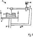
Die Erfindung ist anhand eines Ausführungsbeispieles in den Zeichnungsfiguren näher erläutert. Diese zeigen:The invention is explained in more detail using an exemplary embodiment in the drawing figures. These show:
Die
Im nächsten Verfahrensschritt gemäß
Die Parameter mit Index
Der Laser kann zum bereichsweisen Aufschmelzen und/oder Abtragen der mindestens einen Materiallage
In den
Zweckmäßigerweise erfolgt das bereichsweise Abtragen oder Aufschmelzen nach einer Abkühlphase der letzten aufgetragenen Materiallage
In den
Das Glätten der Materiallagen
In
Die Materiallagen
In
Die Vorrichtung zur Durchführung der oben genannten Verfahren ist mit einem Laser mit Elementen zur Erhöhung der Energiedichte versehen. Diese Vorrichtung ist jedoch in der Zeichnungsfigur
Der Laser bzw. die Strahlumlenkung oder -ablenkung selbst ist an einem elektronisch steuerbaren Kreuzschlittenantrieb, der jedoch aus Gründen der Übersichtlichkeit in die Vorrichtung
Claims (11)
Translated fromGermanPriority Applications (7)
| Application Number | Priority Date | Filing Date | Title |
|---|---|---|---|
| DE10157647ADE10157647C5 (en) | 2001-11-26 | 2001-11-26 | Method for producing three-dimensional workpieces in a laser material processing system or a stereolithography system |
| PCT/DE2002/004188WO2003045669A1 (en) | 2001-11-26 | 2002-11-13 | Method for producing three-dimensional work pieces in a laser material machining unit or a stereolithography unit |
| AT02782771TATE367912T1 (en) | 2001-11-26 | 2002-11-13 | METHOD FOR PRODUCING THREE-DIMENSIONAL WORKPIECES IN A LASER MATERIAL PROCESSING SYSTEM OR A STEREOLITOGRAPHY SYSTEM |
| DE50210570TDE50210570D1 (en) | 2001-11-26 | 2002-11-13 | METHOD FOR PRODUCING THREE DIMENSIONAL WORKPIECES IN A LASER MATERIAL PROCESSING SYSTEM OR A STEREOLITOGRAPHY SYSTEM |
| EP02782771AEP1448359B1 (en) | 2001-11-26 | 2002-11-13 | Method for producing three-dimensional work pieces in a laser material machining unit or a stereolithography unit |
| JP2003547150AJP2005533172A (en) | 2001-11-26 | 2002-11-13 | Method for manufacturing a three-dimensional molded product in a laser material processing unit or an optical modeling unit |
| US10/854,101US20040217095A1 (en) | 2001-11-26 | 2004-05-25 | Method for producing three-dimensional work pieces in a laser material machining unit or a stereolithography unit and unit for performing the method |
Applications Claiming Priority (1)
| Application Number | Priority Date | Filing Date | Title |
|---|---|---|---|
| DE10157647ADE10157647C5 (en) | 2001-11-26 | 2001-11-26 | Method for producing three-dimensional workpieces in a laser material processing system or a stereolithography system |
Publications (3)
| Publication Number | Publication Date |
|---|---|
| DE10157647A1 DE10157647A1 (en) | 2003-06-05 |
| DE10157647B4 DE10157647B4 (en) | 2004-08-26 |
| DE10157647C5true DE10157647C5 (en) | 2012-03-08 |
Family
ID=7706814
Family Applications (2)
| Application Number | Title | Priority Date | Filing Date |
|---|---|---|---|
| DE10157647AExpired - LifetimeDE10157647C5 (en) | 2001-11-26 | 2001-11-26 | Method for producing three-dimensional workpieces in a laser material processing system or a stereolithography system |
| DE50210570TExpired - LifetimeDE50210570D1 (en) | 2001-11-26 | 2002-11-13 | METHOD FOR PRODUCING THREE DIMENSIONAL WORKPIECES IN A LASER MATERIAL PROCESSING SYSTEM OR A STEREOLITOGRAPHY SYSTEM |
Family Applications After (1)
| Application Number | Title | Priority Date | Filing Date |
|---|---|---|---|
| DE50210570TExpired - LifetimeDE50210570D1 (en) | 2001-11-26 | 2002-11-13 | METHOD FOR PRODUCING THREE DIMENSIONAL WORKPIECES IN A LASER MATERIAL PROCESSING SYSTEM OR A STEREOLITOGRAPHY SYSTEM |
Country Status (6)
| Country | Link |
|---|---|
| US (1) | US20040217095A1 (en) |
| EP (1) | EP1448359B1 (en) |
| JP (1) | JP2005533172A (en) |
| AT (1) | ATE367912T1 (en) |
| DE (2) | DE10157647C5 (en) |
| WO (1) | WO2003045669A1 (en) |
Families Citing this family (106)
| Publication number | Priority date | Publication date | Assignee | Title |
|---|---|---|---|---|
| DE10336561B4 (en) | 2003-08-07 | 2019-05-02 | Lim Laserinstitut Mittelsachsen Gmbh | Method for producing a miniature body or microstructured body |
| JP4519560B2 (en)* | 2004-07-30 | 2010-08-04 | 株式会社メディアプラス | Additive manufacturing method |
| JP3687677B1 (en)* | 2004-10-26 | 2005-08-24 | 松下電工株式会社 | Stereolithography method, stereolithography system, and stereolithography program |
| GB0427362D0 (en)* | 2004-12-14 | 2005-01-19 | Sustainable Engine Systems Ltd | Heat exchanger |
| JP4889267B2 (en)* | 2005-09-07 | 2012-03-07 | 共立エレックス株式会社 | Manufacturing method of light emitting diode package |
| US7648740B2 (en)* | 2006-06-12 | 2010-01-19 | The Boeing Company | Method of making improved net-shaped components by hybrid metal deposition processing |
| US8992816B2 (en) | 2008-01-03 | 2015-03-31 | Arcam Ab | Method and apparatus for producing three-dimensional objects |
| DE102008031926A1 (en) | 2008-07-08 | 2010-01-14 | Bego Medical Gmbh | Process for layering steeply inclined surfaces |
| WO2010123413A1 (en)* | 2009-04-24 | 2010-10-28 | Volvo Aero Corporation | A method for manufacturing an engine component |
| CN102470439B (en) | 2009-07-15 | 2016-03-02 | 阿卡姆股份公司 | Manufacture the method and apparatus of three-dimensional body |
| DE102009038165A1 (en)* | 2009-08-20 | 2011-02-24 | Fockele, Matthias, Dr. | Device for the production of form body through layer-wise application of material powder through location-selective hardening of powder to related areas, comprises a process area with a process area base that has a base plain |
| DE102010011059A1 (en) | 2010-03-11 | 2011-09-15 | Global Beam Technologies Ag | Method and device for producing a component |
| DE202010010771U1 (en) | 2010-07-28 | 2011-11-14 | Cl Schutzrechtsverwaltungs Gmbh | Laser melting apparatus for producing a three-dimensional component |
| JP5659607B2 (en)* | 2010-07-30 | 2015-01-28 | 株式会社リコー | Thin film manufacturing method |
| JP5612530B2 (en)* | 2011-04-19 | 2014-10-22 | パナソニック株式会社 | Manufacturing method of three-dimensional shaped object |
| GB2493537A (en)* | 2011-08-10 | 2013-02-13 | Bae Systems Plc | Forming a layered structure |
| GB2493538A (en)* | 2011-08-10 | 2013-02-13 | Bae Systems Plc | Forming a structure by added layer manufacture |
| DE102011087374A1 (en)* | 2011-11-29 | 2013-05-29 | Matthias Fockele | Process for the production of a molded article by layering of material powder |
| EP2797730B2 (en) | 2011-12-28 | 2020-03-04 | Arcam Ab | Method and apparatus for detecting defects in freeform fabrication |
| US10189086B2 (en) | 2011-12-28 | 2019-01-29 | Arcam Ab | Method and apparatus for manufacturing porous three-dimensional articles |
| NL2010139A (en) | 2012-02-03 | 2013-08-06 | Asml Netherlands Bv | Substrate holder, lithographic apparatus, device manufacturing method, and method of manufacturing a substrate holder. |
| IN2014DN09562A (en)* | 2012-05-10 | 2015-07-17 | Renishaw Plc | |
| ES2766834T3 (en) | 2012-05-10 | 2020-06-15 | Renishaw Plc | Manufacturing method of an item |
| DE102012011418A1 (en)* | 2012-06-08 | 2013-12-12 | Universität Rostock | Stereolithography system |
| DE112013006045T5 (en) | 2012-12-17 | 2015-09-17 | Arcam Ab | Additive manufacturing method and device |
| DE202013100888U1 (en) | 2013-03-01 | 2013-04-05 | Marco Barnickel | Three-dimensional bending mold for hoses made of plastic or rubber |
| US9550207B2 (en) | 2013-04-18 | 2017-01-24 | Arcam Ab | Method and apparatus for additive manufacturing |
| US9676031B2 (en) | 2013-04-23 | 2017-06-13 | Arcam Ab | Method and apparatus for forming a three-dimensional article |
| CN105189021B (en)* | 2013-04-29 | 2018-05-15 | 努布鲁有限公司 | Equipment, system and method for 3 D-printing |
| US9950474B2 (en) | 2013-09-13 | 2018-04-24 | Statasys, Inc. | Additive manufacturing system and process with precision substractive technique |
| US9676032B2 (en) | 2013-09-20 | 2017-06-13 | Arcam Ab | Method for additive manufacturing |
| US10434572B2 (en) | 2013-12-19 | 2019-10-08 | Arcam Ab | Method for additive manufacturing |
| US9802253B2 (en) | 2013-12-16 | 2017-10-31 | Arcam Ab | Additive manufacturing of three-dimensional articles |
| US10130993B2 (en) | 2013-12-18 | 2018-11-20 | Arcam Ab | Additive manufacturing of three-dimensional articles |
| US9789563B2 (en) | 2013-12-20 | 2017-10-17 | Arcam Ab | Method for additive manufacturing |
| US9789541B2 (en) | 2014-03-07 | 2017-10-17 | Arcam Ab | Method for additive manufacturing of three-dimensional articles |
| US9636872B2 (en) | 2014-03-10 | 2017-05-02 | Stratasys, Inc. | Method for printing three-dimensional parts with part strain orientation |
| US20150283613A1 (en) | 2014-04-02 | 2015-10-08 | Arcam Ab | Method for fusing a workpiece |
| US9505058B2 (en)* | 2014-05-16 | 2016-11-29 | Xerox Corporation | Stabilized metallic nanoparticles for 3D printing |
| US9486878B2 (en) | 2014-06-20 | 2016-11-08 | Velo3D, Inc. | Apparatuses, systems and methods for three-dimensional printing |
| WO2016016887A1 (en)* | 2014-07-28 | 2016-02-04 | Beyon 3D Ltd | Method and system for fabrication of custom-made molds and concrete-architectural components |
| US9310188B2 (en) | 2014-08-20 | 2016-04-12 | Arcam Ab | Energy beam deflection speed verification |
| US20160059314A1 (en)* | 2014-09-03 | 2016-03-03 | Arcam Ab | Method for improved material properties in additive manufacturing |
| JP2017530033A (en)* | 2014-09-19 | 2017-10-12 | ムーグ インコーポレイテッド | Method for removing defects layer by layer during additive manufacturing |
| DE102014219656A1 (en)* | 2014-09-29 | 2016-03-31 | Siemens Aktiengesellschaft | Process for the production of components for gas turbines, and their products |
| TWI611909B (en)* | 2014-11-29 | 2018-01-21 | National Tsing Hua University | High speed flexible 3d freeform techniques |
| JP2015083540A (en)* | 2014-12-03 | 2015-04-30 | 株式会社リコー | Thin film manufacturing method, piezoelectric element manufacturing method, and recording head manufacturing method |
| US10786865B2 (en) | 2014-12-15 | 2020-09-29 | Arcam Ab | Method for additive manufacturing |
| US9721755B2 (en) | 2015-01-21 | 2017-08-01 | Arcam Ab | Method and device for characterizing an electron beam |
| DE102015100940A1 (en)* | 2015-01-22 | 2016-07-28 | Lilas Gmbh | Method and device for producing a component with an at least partially curved surface |
| DE102015201552A1 (en)* | 2015-01-29 | 2016-08-04 | Bayerische Motoren Werke Aktiengesellschaft | Manufacturing device for the production of three-dimensional objects by means of laser sintering |
| US11014161B2 (en) | 2015-04-21 | 2021-05-25 | Arcam Ab | Method for additive manufacturing |
| PL3095591T3 (en) | 2015-05-19 | 2020-06-29 | MTU Aero Engines AG | Method and device for detecting at least sections of a contour of a layer of an object obtainable by additive processing |
| FR3041278B1 (en)* | 2015-09-23 | 2017-11-03 | Manutech-Usd | SYSTEM AND METHOD FOR ADDITIVE FABRICATION BY LASER FUSION OF A BED OF POWDER |
| US10807187B2 (en) | 2015-09-24 | 2020-10-20 | Arcam Ab | X-ray calibration standard object |
| US10583483B2 (en) | 2015-10-15 | 2020-03-10 | Arcam Ab | Method and apparatus for producing a three-dimensional article |
| US10065270B2 (en) | 2015-11-06 | 2018-09-04 | Velo3D, Inc. | Three-dimensional printing in real time |
| JP6641909B2 (en)* | 2015-11-13 | 2020-02-05 | セイコーエプソン株式会社 | Method for manufacturing three-dimensional object and three-dimensional object |
| US10525531B2 (en) | 2015-11-17 | 2020-01-07 | Arcam Ab | Additive manufacturing of three-dimensional articles |
| US10610930B2 (en) | 2015-11-18 | 2020-04-07 | Arcam Ab | Additive manufacturing of three-dimensional articles |
| US10286603B2 (en) | 2015-12-10 | 2019-05-14 | Velo3D, Inc. | Skillful three-dimensional printing |
| US10399146B2 (en) | 2016-01-12 | 2019-09-03 | Hamilton Sundstrand Corporation | Contour scanning for additive manufacturing process |
| US20170239719A1 (en) | 2016-02-18 | 2017-08-24 | Velo3D, Inc. | Accurate three-dimensional printing |
| US11247274B2 (en) | 2016-03-11 | 2022-02-15 | Arcam Ab | Method and apparatus for forming a three-dimensional article |
| DE102016204905A1 (en)* | 2016-03-23 | 2017-09-28 | Eos Gmbh Electro Optical Systems | Method and device for producing a three-dimensional object |
| US10549348B2 (en) | 2016-05-24 | 2020-02-04 | Arcam Ab | Method for additive manufacturing |
| US11325191B2 (en) | 2016-05-24 | 2022-05-10 | Arcam Ab | Method for additive manufacturing |
| US10525547B2 (en) | 2016-06-01 | 2020-01-07 | Arcam Ab | Additive manufacturing of three-dimensional articles |
| US11691343B2 (en) | 2016-06-29 | 2023-07-04 | Velo3D, Inc. | Three-dimensional printing and three-dimensional printers |
| EP3492244A1 (en) | 2016-06-29 | 2019-06-05 | VELO3D, Inc. | Three-dimensional printing system and method for three-dimensional printing |
| WO2018001705A1 (en)* | 2016-07-01 | 2018-01-04 | Siemens Aktiengesellschaft | Device for additive manufacturing, and method |
| US20180093418A1 (en) | 2016-09-30 | 2018-04-05 | Velo3D, Inc. | Three-dimensional objects and their formation |
| US10792757B2 (en) | 2016-10-25 | 2020-10-06 | Arcam Ab | Method and apparatus for additive manufacturing |
| US20180126460A1 (en) | 2016-11-07 | 2018-05-10 | Velo3D, Inc. | Gas flow in three-dimensional printing |
| JP6768459B2 (en)* | 2016-11-15 | 2020-10-14 | 多田電機株式会社 | Three-dimensional laminated molding method and three-dimensional laminated molding equipment |
| US10987752B2 (en) | 2016-12-21 | 2021-04-27 | Arcam Ab | Additive manufacturing of three-dimensional articles |
| US20180186082A1 (en) | 2017-01-05 | 2018-07-05 | Velo3D, Inc. | Optics in three-dimensional printing |
| CN106825567B (en)* | 2017-01-22 | 2018-12-11 | 清华大学 | Electron beam selective melting and electron beam cut compound increasing material manufacturing method |
| CN110366480A (en)* | 2017-02-28 | 2019-10-22 | 惠普发展公司,有限责任合伙企业 | Amount of radiation for expected surface property level determines |
| US10315252B2 (en) | 2017-03-02 | 2019-06-11 | Velo3D, Inc. | Three-dimensional printing of three-dimensional objects |
| US10449696B2 (en) | 2017-03-28 | 2019-10-22 | Velo3D, Inc. | Material manipulation in three-dimensional printing |
| US11059123B2 (en) | 2017-04-28 | 2021-07-13 | Arcam Ab | Additive manufacturing of three-dimensional articles |
| US11292062B2 (en) | 2017-05-30 | 2022-04-05 | Arcam Ab | Method and device for producing three-dimensional objects |
| US11185926B2 (en) | 2017-09-29 | 2021-11-30 | Arcam Ab | Method and apparatus for additive manufacturing |
| KR102012691B1 (en)* | 2017-10-12 | 2019-08-21 | 한국기계연구원 | Method for manufacturing three dimensional shapes using laser and powder |
| US10529070B2 (en) | 2017-11-10 | 2020-01-07 | Arcam Ab | Method and apparatus for detecting electron beam source filament wear |
| US11072117B2 (en) | 2017-11-27 | 2021-07-27 | Arcam Ab | Platform device |
| US10821721B2 (en) | 2017-11-27 | 2020-11-03 | Arcam Ab | Method for analysing a build layer |
| JP7120253B2 (en)* | 2017-12-12 | 2022-08-17 | 株式会社ニコン | Processing device and processing method, processing method, and modeling device and modeling method |
| US12350754B2 (en) | 2017-12-22 | 2025-07-08 | Arcam Ab | Electron beam source and the use of the same |
| US11517975B2 (en) | 2017-12-22 | 2022-12-06 | Arcam Ab | Enhanced electron beam generation |
| US10272525B1 (en) | 2017-12-27 | 2019-04-30 | Velo3D, Inc. | Three-dimensional printing systems and methods of their use |
| US10144176B1 (en) | 2018-01-15 | 2018-12-04 | Velo3D, Inc. | Three-dimensional printing systems and methods of their use |
| US10800101B2 (en) | 2018-02-27 | 2020-10-13 | Arcam Ab | Compact build tank for an additive manufacturing apparatus |
| US11267051B2 (en) | 2018-02-27 | 2022-03-08 | Arcam Ab | Build tank for an additive manufacturing apparatus |
| US11400519B2 (en) | 2018-03-29 | 2022-08-02 | Arcam Ab | Method and device for distributing powder material |
| DE102018205820A1 (en)* | 2018-04-17 | 2019-10-17 | Eos Gmbh Electro Optical Systems | Selective re-exposure |
| US10520923B2 (en) | 2018-05-22 | 2019-12-31 | Mantle Inc. | Method and system for automated toolpath generation |
| JP7396613B2 (en)* | 2018-05-31 | 2023-12-12 | 地方独立行政法人東京都立産業技術研究センター | Laminated manufacturing equipment, processing method for three-dimensional shaped objects, three-dimensional shaped objects and molds |
| JP7234637B2 (en)* | 2019-01-11 | 2023-03-08 | セイコーエプソン株式会社 | Manufacturing method of three-dimensional model |
| CA3148849A1 (en) | 2019-07-26 | 2021-02-04 | Velo3D, Inc. | Quality assurance in formation of three-dimensional objects |
| KR102210719B1 (en)* | 2019-08-02 | 2021-02-02 | 한국과학기술원 | 3d printer having micro/nano hole drilling function and operating method thereof |
| JP7435626B2 (en)* | 2019-12-26 | 2024-02-21 | 株式会社ニコン | Beam processing equipment |
| CN111215745B (en)* | 2020-02-19 | 2021-07-27 | 南京理工大学 | A variable process defect control method for laser-consolidated conductive paste |
| JP7503743B2 (en)* | 2020-03-02 | 2024-06-21 | パナソニックIpマネジメント株式会社 | A method for manufacturing a three-dimensional object |
| DE102021111966A1 (en)* | 2021-05-07 | 2022-11-10 | Fraunhofer-Gesellschaft zur Förderung der angewandten Forschung eingetragener Verein | Process and arrangement for the additive manufacturing of components using material extrusion |
Citations (12)
| Publication number | Priority date | Publication date | Assignee | Title |
|---|---|---|---|---|
| JPH0295830A (en)* | 1988-10-01 | 1990-04-06 | Matsushita Electric Works Ltd | Forming method of three dimensional shape |
| DE3711470C2 (en)* | 1987-04-04 | 1990-06-07 | Fraunhofer-Gesellschaft Zur Foerderung Der Angewandten Forschung Ev, 8000 Muenchen, De | |
| EP0406513A1 (en)* | 1989-07-07 | 1991-01-09 | Mitsui Engineering and Shipbuilding Co, Ltd. | Optical molding method |
| DE4416901A1 (en)* | 1994-05-13 | 1995-11-16 | Eos Electro Optical Syst | Prodn of three=dimensional objects |
| DE19533960A1 (en)* | 1995-09-13 | 1997-03-20 | Fraunhofer Ges Forschung | Method and device for producing metallic workpieces |
| DE19649865C1 (en)* | 1996-12-02 | 1998-02-12 | Fraunhofer Ges Forschung | Shaped body especially prototype or replacement part production |
| DE19715702A1 (en)* | 1997-04-15 | 1998-10-22 | Fraunhofer Ges Forschung | Process for the selective removal of one or more layers |
| DE19818469A1 (en)* | 1997-04-25 | 1998-10-29 | Toyota Motor Co Ltd | Method for producing a layered component |
| DE10007962C1 (en)* | 2000-02-22 | 2001-07-26 | Werkzeugbau Siegfried Hofmann | Production of an injection molded or die cast mold comprises using a multiple step process to produce a hardened surface layer with a low degree of roughness |
| DE10053741C1 (en)* | 2000-10-30 | 2002-02-21 | Concept Laser Gmbh | Machine for sintering, removing material from or marking surface with laser beam uses trolleys which include container for workpieces and have working platform whose height can be adjusted |
| DE10042132A1 (en)* | 2000-08-28 | 2002-03-28 | Concept Laser Gmbh | Production of sintered workpieces involves binding layers of material by irradiation, where each layer comprises core and coating, and irradiation is controlled to produce complete fusion of material in coating in at least its surface area |
| DE10148967A1 (en)* | 2000-10-05 | 2002-04-18 | Matsushita Electric Works Ltd | Three-dimensional object formation method involves irradiating optical beam on predetermined portion of consequent powder layer repeatedly to form sintered layer |
Family Cites Families (3)
| Publication number | Priority date | Publication date | Assignee | Title |
|---|---|---|---|---|
| US4863538A (en)* | 1986-10-17 | 1989-09-05 | Board Of Regents, The University Of Texas System | Method and apparatus for producing parts by selective sintering |
| US5398193B1 (en)* | 1993-08-20 | 1997-09-16 | Alfredo O Deangelis | Method of three-dimensional rapid prototyping through controlled layerwise deposition/extraction and apparatus therefor |
| US6583381B1 (en)* | 1999-05-24 | 2003-06-24 | Potomac Photonics, Inc. | Apparatus for fabrication of miniature structures |
- 2001
- 2001-11-26DEDE10157647Apatent/DE10157647C5/ennot_activeExpired - Lifetime
- 2002
- 2002-11-13WOPCT/DE2002/004188patent/WO2003045669A1/enactiveIP Right Grant
- 2002-11-13JPJP2003547150Apatent/JP2005533172A/enactivePending
- 2002-11-13EPEP02782771Apatent/EP1448359B1/ennot_activeExpired - Lifetime
- 2002-11-13ATAT02782771Tpatent/ATE367912T1/ennot_activeIP Right Cessation
- 2002-11-13DEDE50210570Tpatent/DE50210570D1/ennot_activeExpired - Lifetime
- 2004
- 2004-05-25USUS10/854,101patent/US20040217095A1/ennot_activeAbandoned
Patent Citations (12)
| Publication number | Priority date | Publication date | Assignee | Title |
|---|---|---|---|---|
| DE3711470C2 (en)* | 1987-04-04 | 1990-06-07 | Fraunhofer-Gesellschaft Zur Foerderung Der Angewandten Forschung Ev, 8000 Muenchen, De | |
| JPH0295830A (en)* | 1988-10-01 | 1990-04-06 | Matsushita Electric Works Ltd | Forming method of three dimensional shape |
| EP0406513A1 (en)* | 1989-07-07 | 1991-01-09 | Mitsui Engineering and Shipbuilding Co, Ltd. | Optical molding method |
| DE4416901A1 (en)* | 1994-05-13 | 1995-11-16 | Eos Electro Optical Syst | Prodn of three=dimensional objects |
| DE19533960A1 (en)* | 1995-09-13 | 1997-03-20 | Fraunhofer Ges Forschung | Method and device for producing metallic workpieces |
| DE19649865C1 (en)* | 1996-12-02 | 1998-02-12 | Fraunhofer Ges Forschung | Shaped body especially prototype or replacement part production |
| DE19715702A1 (en)* | 1997-04-15 | 1998-10-22 | Fraunhofer Ges Forschung | Process for the selective removal of one or more layers |
| DE19818469A1 (en)* | 1997-04-25 | 1998-10-29 | Toyota Motor Co Ltd | Method for producing a layered component |
| DE10007962C1 (en)* | 2000-02-22 | 2001-07-26 | Werkzeugbau Siegfried Hofmann | Production of an injection molded or die cast mold comprises using a multiple step process to produce a hardened surface layer with a low degree of roughness |
| DE10042132A1 (en)* | 2000-08-28 | 2002-03-28 | Concept Laser Gmbh | Production of sintered workpieces involves binding layers of material by irradiation, where each layer comprises core and coating, and irradiation is controlled to produce complete fusion of material in coating in at least its surface area |
| DE10148967A1 (en)* | 2000-10-05 | 2002-04-18 | Matsushita Electric Works Ltd | Three-dimensional object formation method involves irradiating optical beam on predetermined portion of consequent powder layer repeatedly to form sintered layer |
| DE10053741C1 (en)* | 2000-10-30 | 2002-02-21 | Concept Laser Gmbh | Machine for sintering, removing material from or marking surface with laser beam uses trolleys which include container for workpieces and have working platform whose height can be adjusted |
Non-Patent Citations (3)
| Title |
|---|
| Bedienungsanleitung der EOSINT M 250 Xtended der Fa. EOS GmbH Electro Optical Systems. 1999.* |
| Erasenthiran, P. et al. "An investigation of step shaping using Nd:YAG laser for parts produced by Laminated Object Manufacturing technique", in: Laser Assisted Net Shape Engineenng 2: Proceedings of the 30th International CIRP Seminar on Manufacturing Systems - LANE 97, Erlangen, September 23 -26, 1997 / ed. by M. Geiger; F. Vollertsen for CIRP, WGP and WLT - Bamberg, Meisenbach, 1997, S. 541-553. ISBN 3-87525-090-7.* |
| Lohner, A.: Design Rules. EOS GmbH 1/97, S. 1 - 13.* |
Also Published As
| Publication number | Publication date |
|---|---|
| US20040217095A1 (en) | 2004-11-04 |
| EP1448359B1 (en) | 2007-07-25 |
| EP1448359A1 (en) | 2004-08-25 |
| ATE367912T1 (en) | 2007-08-15 |
| DE10157647B4 (en) | 2004-08-26 |
| DE50210570D1 (en) | 2007-09-06 |
| JP2005533172A (en) | 2005-11-04 |
| DE10157647A1 (en) | 2003-06-05 |
| WO2003045669A1 (en) | 2003-06-05 |
Similar Documents
| Publication | Publication Date | Title |
|---|---|---|
| DE10157647C5 (en) | Method for producing three-dimensional workpieces in a laser material processing system or a stereolithography system | |
| DE10148967B4 (en) | Method and device for producing a three-dimensional object | |
| EP3225334B1 (en) | Method and apparatus for additive manufacture of at least one component area of a component | |
| EP1332039B1 (en) | Device for sintering, removing material and/or labeling by means of electromagnetically bundled radiation and method for operating the device | |
| EP2300218B1 (en) | Dual method for the small-scale manufacture of products | |
| DE69911178T3 (en) | METHOD FOR THE FAST MANUFACTURE OF A PROTOTYP BY LASER INTERRUPTION AND DEVICE THEREFOR | |
| EP0790875B1 (en) | Process and device for making metal workpieces | |
| DE19853978C1 (en) | Apparatus for selective laser smelting comprises a roller that moves over the processing surface using an element to distribute powder | |
| DE69031061T2 (en) | Multi-material systems for sintering with selective radiation using powder | |
| DE10344902B4 (en) | Method for producing a three-dimensional object | |
| DE102016211952A1 (en) | Coating unit, coating method, apparatus and method for generatively producing a three-dimensional object | |
| EP3242762A1 (en) | Device and generative layer-building process for producing a three-dimensional object by multiple beams | |
| WO2002042056A1 (en) | Generative method for producing a part and device for carrying out this method | |
| WO2008116518A1 (en) | Method and device for the production of a three-dimensional object | |
| EP3010672A2 (en) | Device and method for additively producing at least one component region of a component | |
| EP3017895A1 (en) | Manufacture of a component through selective laser melting | |
| EP3216546A1 (en) | Micro-forging in a generative production method | |
| EP1397222B1 (en) | Procedure for the production of a work piece with exact geometry . | |
| WO2009080016A2 (en) | Method for altering the beam diameter of a laser beam on a machining plane and assembly designed therefor | |
| WO2012062253A2 (en) | Device for producing, repairing, and/or replacing a component by means of a powder that can be solidified by energy radiation, and a method and a component produced according to the method | |
| EP0558870A1 (en) | Free welding of metal structures casing a laser | |
| DE102010046467A1 (en) | Device, useful for manufacturing, repairing and/or replacing component, preferably aircraft component by powder solidifiable by radiation energy of radiation energy source, comprises fixed construction platform with frame | |
| DE112017005812T5 (en) | METHOD FOR PRODUCING A 3D PRINTED SUBJECT | |
| WO2017001098A1 (en) | Apparatus and method for powder-based laser build-up welding | |
| EP4584037A1 (en) | Method and device for producing micro parts and micro components by means of additive manufacturing using micro laser sintering |
Legal Events
| Date | Code | Title | Description |
|---|---|---|---|
| OP8 | Request for examination as to paragraph 44 patent law | ||
| 8363 | Opposition against the patent | ||
| 8327 | Change in the person/name/address of the patent owner | Owner name:CL SCHUTZRECHTSVERWALTUNGS GMBH, 96215 LICHTENFELS | |
| R034 | Decision of examining division/federal patent court maintaining patent in limited form now final | Effective date:20111013 | |
| R206 | Amended patent specification | Effective date:20120308 | |
| R071 | Expiry of right |