CN85108242A - Electric screwdriver - Google Patents
Electric screwdriverDownload PDFInfo
- Publication number
- CN85108242A CN85108242ACN198585108242ACN85108242ACN85108242ACN 85108242 ACN85108242 ACN 85108242ACN 198585108242 ACN198585108242 ACN 198585108242ACN 85108242 ACN85108242 ACN 85108242ACN 85108242 ACN85108242 ACN 85108242A
- Authority
- CN
- China
- Prior art keywords
- switch
- motor
- gear
- lever
- gear reducer
- Prior art date
- Legal status (The legal status is an assumption and is not a legal conclusion. Google has not performed a legal analysis and makes no representation as to the accuracy of the status listed.)
- Pending
Links
Images


Classifications
- B—PERFORMING OPERATIONS; TRANSPORTING
- B25—HAND TOOLS; PORTABLE POWER-DRIVEN TOOLS; MANIPULATORS
- B25B—TOOLS OR BENCH DEVICES NOT OTHERWISE PROVIDED FOR, FOR FASTENING, CONNECTING, DISENGAGING OR HOLDING
- B25B23/00—Details of, or accessories for, spanners, wrenches, screwdrivers
- B25B23/14—Arrangement of torque limiters or torque indicators in wrenches or screwdrivers
- B25B23/147—Arrangement of torque limiters or torque indicators in wrenches or screwdrivers specially adapted for electrically operated wrenches or screwdrivers
- B—PERFORMING OPERATIONS; TRANSPORTING
- B25—HAND TOOLS; PORTABLE POWER-DRIVEN TOOLS; MANIPULATORS
- B25B—TOOLS OR BENCH DEVICES NOT OTHERWISE PROVIDED FOR, FOR FASTENING, CONNECTING, DISENGAGING OR HOLDING
- B25B21/00—Portable power-driven screw or nut setting or loosening tools; Attachments for drilling apparatus serving the same purpose
Landscapes
- Engineering & Computer Science (AREA)
- Mechanical Engineering (AREA)
- Details Of Spanners, Wrenches, And Screw Drivers And Accessories (AREA)
Abstract
Translated fromChineseDescription
Translated fromChinese这是一项关于推动式电动改锥的发明。电动改锥是一种适用于拧紧螺钉和螺帽的手用电动工具。This is an invention of a push electric screwdriver. An electric screwdriver is a hand electric tool suitable for tightening screws and nuts.
近来,推动式电动改锥业已获得广泛应用。在这种工具中,当锥头一顶螺钉,电动机就旋转;而当螺钉拧紧到预定的力矩时,在离合器的作用下,电动机的电源被切断。Recently, push-type electric screwdrivers have been widely used. In this tool, when the cone head hits the screw, the motor rotates; and when the screw is tightened to a predetermined torque, under the action of the clutch, the power supply of the motor is cut off.
下面利用图9举例说明原有的推动式电动改锥的结构(细节请参阅日本专利公开№2036/75)。在图9中,标号1、2和3分别表示电动机、行星式齿轮减速器和离合器。标号4表示包容这些另部件的外壳。标号5表示开关拉杆,它穿过行星式齿轮减速器2和电动机1,借助销钉6而连接到开关7。开关7用以接通和断开电动机1的电源。标号8代表锥头,在拧螺钉过程中它一直顶着螺钉,使离合器3动作,从而使开关拉杆5沿箭头a的方向运动,把开关7接通,当螺钉拧到预定的力矩值时,离合器3使开关拉杆5向箭头b的方向运动,把开关7断开,电动机随即停车。The following uses Fig. 9 to illustrate the structure of the original push-type electric screwdriver (for details, please refer to Japanese Patent Publication No. 2036/75). In Fig. 9,
但是,在上述的原有的结构中,电动机1的转轴必须作成空心的,开关拉杆5方能穿过。这对电动机的制造成本及刚度(当电动机很长时)都很不利。其次,开关拉杆5越长,弯曲程度也越大,它在电动机转轴和行星式齿轮减速器的中间滑动不够均衡,造成开关动作不稳定。此外,原有技术的问题还在于即使穿行电动机1、行星式齿轮减速器2和离合器3的开关拉杆5在其纵向尺寸方面具有良好的精度,它对开关7的推动也会产生不足或过头的问题,原因是三个零部件(即电动机1、行星式齿轮减速器2和离合器3)的尺寸公差形成了累积误差。But, in above-mentioned original structure, the rotating shaft of motor 1 must be made hollow, and switch pull rod 5 just can pass through. This is detrimental to the manufacturing cost and stiffness (when the motor is long) of the motor. Secondly, the longer the switch pull rod 5 is, the greater the degree of bending is. Its sliding between the motor shaft and the planetary gear reducer is not balanced enough, resulting in unstable switching action. In addition, the problem of the prior art is that even if the switch rod 5 of the travel motor 1, the planetary gear reducer 2 and the
本发明旨在解决原有技术的上述缺陷。本发明提出一种新型电动改锥,其开关拉杆尽可能短,而且开关置于电动机和齿轮减速器之间并靠近离合器,这样便可消除由于累积误差所引起的开关动作行程的偏差。电动机的转轴可作成实心的,对制造成本和刚度均有利。The present invention aims to solve the above-mentioned drawbacks of the prior art. The invention proposes a new type of electric screwdriver, the switch pull rod is as short as possible, and the switch is placed between the motor and the gear reducer and close to the clutch, so that the deviation of the switch action stroke caused by the accumulated error can be eliminated. The rotating shaft of the motor can be made solid, which is beneficial to manufacturing cost and rigidity.
为了解决上述问题,本发明所提出的电动改锥包括一个不用内齿轮而用作行星式排列的双中间齿轮组构成的减速机构,以取代原来的行星式齿轮减速器;还包括一个置于电动机和减速器之间的用以根据锥头的轴向运动而引动开关的开关操作机构。In order to solve the above problems, the electric screwdriver proposed by the present invention includes a reduction mechanism that does not use an internal gear but is used as a planetary arrangement of double intermediate gear sets to replace the original planetary gear reducer; it also includes a motor and The switch operating mechanism between the reducer is used to actuate the switch according to the axial movement of the cone head.
在本发明所提出的结构中,开关与连接到离合器的开关拉杆之间的距离很短,以消除开关动作行程由于上述零部件的轴向累积误差可能引起的偏差。在齿轮减速器上装有开关的引动零件,它能准确地把开关拉杆的运动传递给开关,因此很短的开关拉杆即可使开关开合。开关置于电动机和齿轮减速器之间,可使电动机的转轴作成实心的。In the structure proposed by the present invention, the distance between the switch and the switch pull rod connected to the clutch is very short to eliminate the deviation of the switch action stroke due to the axial cumulative error of the above-mentioned parts. The actuating part of the switch is installed on the gear reducer, which can accurately transmit the movement of the switch pull rod to the switch, so a very short switch pull rod can make the switch open and close. The switch is placed between the motor and the gear reducer, so that the rotating shaft of the motor can be made solid.
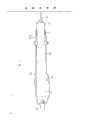
图1所示是体现本发明的电动改锥的概貌图;Shown in Fig. 1 is the overview figure that embodies electric screwdriver of the present invention;
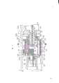
图2所示是体现本发明第一种方案的齿轮减速器的局部剖面图;Figure 2 is a partial sectional view of a gear reducer embodying the first solution of the present invention;
图3所示是沿图2中Ⅲ-Ⅲ线展示的剖面图;Shown in Fig. 3 is the sectional view shown along line III-III in Fig. 2;
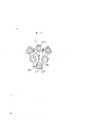
图4至图6所示是体现本发明第一种方案的说明结合到离合器装置的主要零部件的剖面图;Figures 4 to 6 are cross-sectional views of the main components of the clutch device that embody the first solution of the present invention;
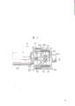
图7所示是体现本发明第二种方案的整个减速器的剖面图;Figure 7 is a sectional view of the entire reducer embodying the second solution of the present invention;
图8所示是沿图7中Ⅷ-Ⅷ线展示的剖面图;Shown in Fig. 8 is the sectional view shown along the Ⅷ-Ⅷ line in Fig. 7;
图9所示是电动改锥原有结构的一般剖面图。Figure 9 is a general sectional view of the original structure of the electric screwdriver.
下面结合附图将体现本发明所提出的电动改锥的结构方案说明如下。Below in conjunction with accompanying drawing will embody the structure scheme of the electric screwdriver proposed by the present invention to illustrate as follows.
图1所示是体现本发明的电动改锥的剖面图。图中,标号8、9、10、11、12、13和14分别表示锥头、电动机、齿轮减速器、离合器、电源引线、用以改变锥头8旋转方向的开关和用以调节离合器11力矩大小的螺帽。标号15a和15b分别表示包容上述另部件的外壳。Figure 1 is a sectional view of an electric screwdriver embodying the present invention. In the figure, the
图2所示是结合开关操作机构的齿轮减速器10。标号16表示电动机上与若干中间齿轮17啮合的齿轮,每个中间齿轮都包含一级齿轮部分17a和二级齿轮部分17b,两者形成一个整体。输出端齿轮18与中间齿轮17的二级齿轮部分啮合,它是滑动嵌到中部位置,并有一个穿过离合器11的开关拉杆19。输出端齿轮18的本体靠轴承20支持,其前端通过管箍与离合器11连接起来(旋转连接),该管箍系由离合器11中的轴承21支持的。中间齿轮17在两端用轴衬25a和25b支持,后者分别与上平板23和下平板24压入配合,并用垫圈26补偿轴向间隙。在上下平板23和24之间偏心放置若干导杆27。把若干轴衬29与在电动机齿轮16及输出端齿轮18之间放置的滑块28配合到一起,每个轴衬可沿一根导杆27滑动。同开关拉杆19的一个端面紧靠着的中间轴衬30与滑块28系压入配合。用以引动开关31的拉杆32也与滑块28压入配合。标号33和34分别表示压缩弹簧和弹簧座。标号35表示轴套,它与上平板23构成整体结构,借以支持轴承36。Figure 2 shows a gear reducer 10 combined with a switch operating mechanism.
图3所示是沿图2中的Ⅲ-Ⅲ线展示的剖面图。图中轴衬29相对导杆27保持不转,并能相对滑块28的中心位置稍作前后运动。Figure 3 is a cross-sectional view along line III-III in Figure 2 . In the figure, the
在图4所示的离合器11中,凸轮轴37支持环形凸轮38。标号40表示锤形环,其沟槽里含有滚珠39,它们适于在环形凸轮38的凸轮斜面上作上下运动。该锤形环与凸轮轴37系滑动配合。锥头座41装在凸轮轴37的中心孔内。在锥头座41与凸轮轴37之间装有恢复弹簧42。锥头上装有爪形护圈44。后者可以轴向滑动,但是由于钢球43的限制不能绕自己的轴线旋转。爪形护圈44的一端为爪齿44a,适于同锤形环40端部的爪齿40a啮合。在爪形护圈44和锁环45之间放置复位弹簧46。锁环45位于锥头座41的中心附近。锁簧49装在凸轮轴37的中心孔内,介于锁紧凸轮47的左端面和凸轮轴轴衬48之间,后者系与凸轮轴47压入配合。锁紧凸轮47位在凸轮轴37及锥头座41的中心孔内。开关拉杆19轴向穿过凸轮轴轴衬48的中间而与开关31相连接,其状如图2所示。包容在锥头座41的径向孔内的钢球50与锁紧凸轮47的头部47a相连。标号51表示包容离合器11的外壳。力矩弹簧54装在离合器外壳51的内表面和锤形环40之间,并从用推力轴承52支持的弹簧座53a延伸到弹簧座53b。标号55表示力矩调节螺帽,它与离合器外壳51系细蚊连接,左端有环56。在离合器外壳51内装有若干销钉57。当力矩调节螺帽55移动时,它们顶着弹簧座53b。标号58表示与离合器外壳51相连的套筒。套筒弹簧59置于离合器外壳51及套筒58之间。借助钢球60可以防止套筒58相对离合器外壳61旋转。套筒58在前部有一个压入配合的轴衬61,该轴衬通过锁环62而防止移动。标号63、64和65分别表示装在套筒58上的锁环、装于凸轮轴37的锁环和防止锥头8松动的钢球。当锥头8顶到螺钉上时(图中未表示),爪形护圈44的爪齿44a即与锤状环40的爪齿40a啮合,并推动开关拉杆19,把开关31引动,使电动机9开车。In the clutch 11 shown in FIG. 4 , a
上述结构形式的电动改锥的动作过程可对照附图说明如下。The course of action of the electric screwdriver of above-mentioned structural form can be described as follows with reference to accompanying drawing.
当锥头8顶到螺钉(图中未表示)并沿图2中箭头c的方向运动时,开关拉杆19亦沿同一方向通过离合器11而运动,并且推动中心轴衬30,使滑块28运动,这样就使与滑块28固定的拉杆32也运动相同的距离,引起开关31动作,结果电动机9开动。电动机9的转矩通过电动机齿轮16和中间齿轮减速器17传递给输出端齿轮13,在转速降低时,转矩增加,这样就把力矩传到了离合器11。When the
对照图5,当施于螺钉的力矩达到预定值时,锥头8、锥头座41和爪形护圈44停止运动,但电动机9有保持转动的趋势,以致通过减速器10从电动机9传递出来的驱动力被传给凸轮轴37,使环形凸轮38旋转,这样就使钢球39移动到环形凸轮38的凸轮斜面38a的最高位置,并使锤形环40沿箭头A的方向偏移,以致锤形环40在其右端向右推动爪形护圈44(图5)。这时,钢球50在锁紧弹簧49的偏移力的作用下产生运动,使锁紧凸轮47运动,并与锁紧凸轮47的头部47a脱离接触,以致钢球50完全进入锥头座41的径向孔内。这样,开关拉杆19就返回到其原始位置。而滑块28在压簧33的偏移力的作用下运动并断开开关31,使电动机9停车(参阅图2)。当钢球39越过凸轮斜面38a的最高位置时(参阅图6),锤形环40便沿箭头B的方向运动。与此同时,爪形护圈44由于钢球50的限制不能返回其原始位置,以致爪齿30a和44a脱离啮合,这样就防止了把驱动力继续传递给锥头8。5, when the torque applied to the screw reaches a predetermined value, the
在上述结构形式的电动改锥中,齿轮减速器与开关操作机构结合在一起。开关拉杆19的移动量之所以能够有效地传递给开关31,是靠开关拉杆19与中心轴衬30的紧密啮合。后者同滑块28系压入配合,可沿装在上下平板23和24之间的导杆27滑动。滑块28上有固定的拉杆32。In the electric screwdriver of the above structural form, the gear reducer is combined with the switch operating mechanism. The reason why the movement amount of the switch pull
另一种体现本发明电动改锥减速器及开关操作机构的结构方案可参照图7、图8说明如下。Another structural solution embodying the electric screwdriver reducer and the switch operating mechanism of the present invention can be described as follows with reference to FIG. 7 and FIG. 8 .
在这两个图上所示的开关操作机构与图2所示的区别在于开关拉杆19紧靠着杠杆66。该杠杆可绕轴71旋转。轴71由轴座69支持。后者通过螺钉68固定到介于上下平板23和24之间并借锁环70固定的支柱67上。杠杆66的旋转带动销钉72,使之克服压簧73的偏移力在轴座69中滑动。这样就导致开关31的开合。The switch operating mechanism shown in these two figures differs from that shown in FIG. 2 in that the switch pull
具有图7和图8所示的减速器和开关操作机构的电动改锥的工作过程略如下述。The working process of the electric screwdriver with the speed reducer shown in Figure 7 and Figure 8 and the switch operating mechanism is slightly as follows.
当开关拉杆19沿箭头c的方向运动时,杠杆66将绕轴71循箭头e的方向旋转(图7)。杠杆66推动销钉72端部的凸缘72a。后者与杠杆66的U形切口相配合,并沿图7中箭头g的方向克服压簧73的偏移力推动销钉72。这时,开关31(利用b触头)在相反的一端或销钉72的前端被接通,电动机9开动。当开关拉杆19沿箭头d的方向运动时,杠杆66循箭头f的方向旋转,销钉72沿箭头h的方向运动,使开关31关断,电动机9停车。When the switch pull
在中间齿轮17和输出齿轮18之间通过杠杆66推动销钉72来实现开关动作,可使开关拉杆19的移动量有效地传递给开关31。Between the
从以上说明可知本发明的电动改锥包括开关操作机构和齿轮减速器系统,它们置于电动机和离合器之间。当锥头沿轴向运动时,开关即行动作。这就消除了应用穿过电动机空心轴的长开关拉杆的必要性。开关拉杆由于过长易于弯曲所引起的运动不稳定性以及制造空心转轴所引起的成本增加等缺陷亦随之消除。开关拉杆的稳定性提高。开关操作机构离离合器远离开关近,这样开关动作行程就不致遭受在它们之间放置的另部件的纵向尺寸累积误差的不良影响,在电动机起动和停止过程中即可达到预期的稳定性。It can be seen from the above description that the electric screwdriver of the present invention includes a switch operating mechanism and a gear reducer system, which are placed between the motor and the clutch. When the cone head moves in the axial direction, the switch will act immediately. This eliminates the need to apply long switch levers that pass through the hollow shaft of the motor. Defects such as movement instability caused by too long and easy to bend the switch pull rod and cost increase caused by manufacturing the hollow rotating shaft are also eliminated. Improved stability of the switch lever. The switch operating mechanism is close to the clutch and away from the switch, so that the switch action stroke will not be adversely affected by the cumulative error of the longitudinal dimension of the other parts placed between them, and the expected stability can be achieved during the starting and stopping of the motor.
Claims (5)
Translated fromChineseApplications Claiming Priority (2)
| Application Number | Priority Date | Filing Date | Title |
|---|---|---|---|
| JP242836/84 | 1984-11-16 | ||
| JP59242836AJPS61121877A (en) | 1984-11-16 | 1984-11-16 | electric screwdriver |
Publications (1)
| Publication Number | Publication Date |
|---|---|
| CN85108242Atrue CN85108242A (en) | 1986-06-10 |
Family
ID=17095012
Family Applications (1)
| Application Number | Title | Priority Date | Filing Date |
|---|---|---|---|
| CN198585108242APendingCN85108242A (en) | 1984-11-16 | 1985-11-16 | Electric screwdriver |
Country Status (5)
| Country | Link |
|---|---|
| US (1) | US4617843A (en) |
| JP (1) | JPS61121877A (en) |
| CN (1) | CN85108242A (en) |
| DE (1) | DE3540652C2 (en) |
| GB (1) | GB2168635B (en) |
Cited By (5)
| Publication number | Priority date | Publication date | Assignee | Title |
|---|---|---|---|---|
| CN100355532C (en)* | 2004-10-21 | 2007-12-19 | 株式会社牧田 | Tightening tool |
| CN100372652C (en)* | 2004-10-21 | 2008-03-05 | 株式会社牧田 | Tightening tool |
| CN102848358A (en)* | 2011-06-27 | 2013-01-02 | 罗伯特·博世有限公司 | Handheld machine tool, especially drilling machine or screwdriver |
| CN103831795A (en)* | 2012-11-26 | 2014-06-04 | 苏州宝时得电动工具有限公司 | Handheld tool |
| WO2018121722A1 (en)* | 2016-12-30 | 2018-07-05 | 博世电动工具(中国)有限公司 | Screwdriver |
Families Citing this family (18)
| Publication number | Priority date | Publication date | Assignee | Title |
|---|---|---|---|---|
| US4721169A (en)* | 1986-05-14 | 1988-01-26 | Matsushita Electric Industrial Co., Ltd. | Electric driver with torque-adjustable clutch mechanism |
| DE3620137A1 (en)* | 1986-06-14 | 1987-12-17 | Raimund Wilhelm | SCREW MACHINE AND METHOD FOR THEIR OPERATION |
| JPS6426166U (en)* | 1987-08-05 | 1989-02-14 | ||
| US4878404A (en)* | 1988-09-14 | 1989-11-07 | Liao Hsieh Yuan | Electric screwdriver |
| US5557990A (en)* | 1995-07-27 | 1996-09-24 | Shin; Fu-Zong | Actuating device for use in powered screwdriver |
| US5738177A (en)* | 1995-07-28 | 1998-04-14 | Black & Decker Inc. | Production assembly tool |
| USD437758S1 (en) | 2000-01-11 | 2001-02-20 | Choon Nang Electrical Appliances Mfy., Ltd. | Rotary driving tool |
| USD433905S (en)* | 2000-05-19 | 2000-11-21 | Black & Decker Inc. | Rotary tool |
| US6758116B2 (en)* | 2001-06-28 | 2004-07-06 | Porter-Cable/Delta | Depth adjusting system for a screw gun |
| US7185562B2 (en)* | 2004-12-08 | 2007-03-06 | Osteomed L.P. | Disposable battery powered screw driver, locking mechanism, and accessories |
| DE102012215025A1 (en) | 2012-08-23 | 2014-02-27 | Metabowerke Gmbh | Powered machine tool, in particular angle grinder or straight grinder |
| DE102012218272A1 (en)* | 2012-10-08 | 2014-04-10 | Robert Bosch Gmbh | Hand tool |
| EP2903784B1 (en)* | 2012-10-08 | 2021-06-23 | Robert Bosch GmbH | Hand-held machine tool |
| CN102922495A (en)* | 2012-11-13 | 2013-02-13 | 苏州安必瑟斯机电技术有限公司 | Electric tool |
| US20150059531A1 (en) | 2013-08-29 | 2015-03-05 | Ingersoll-Rand Company | Ratchet Tools |
| ES2732189T3 (en) | 2014-10-08 | 2019-11-21 | Medartis Holding Ag | Electric machine tool, in particular electric screwdriver for use in surgery |
| US12090606B2 (en) | 2020-09-22 | 2024-09-17 | Snap-On Incorporated | Tool and motor anti-rotation |
| DE102021201181A1 (en)* | 2021-02-09 | 2022-08-11 | Robert Bosch Gesellschaft mit beschränkter Haftung | Hand-held power tool and method for activating a drive motor of a hand-held power tool |
Family Cites Families (9)
| Publication number | Priority date | Publication date | Assignee | Title |
|---|---|---|---|---|
| US1711520A (en)* | 1925-07-11 | 1929-05-07 | Black & Decker Mfg Co | Screw driver and wrench |
| US1839648A (en)* | 1931-03-20 | 1932-01-05 | Black & Decker Mfg Co | Portable motor driven screw driver |
| GB376638A (en)* | 1931-12-18 | 1932-07-14 | Edwin Lewis Connell | Improvements in portable, motor-driven screw drivers |
| US2796161A (en)* | 1955-07-26 | 1957-06-18 | Clinton L Graybill | Hydraulically actuated attachment for power-driven tool chucks |
| US2979089A (en)* | 1958-04-24 | 1961-04-11 | Hanns Fickert | Portable battery-energized screw driver |
| US3866493A (en)* | 1974-04-01 | 1975-02-18 | Chester A Ringerud | Air-operated hand tool |
| JPS582036B2 (en)* | 1977-11-01 | 1983-01-13 | 松下電器産業株式会社 | electric screw driver |
| CA1076854A (en)* | 1977-08-19 | 1980-05-06 | William J. Baker | Torque responsive shutoff mechanism for power tool |
| DE3274631D1 (en)* | 1981-04-13 | 1987-01-22 | Desoutter Ltd | Motor driven power tool |
- 1984
- 1984-11-16JPJP59242836Apatent/JPS61121877A/enactivePending
- 1985
- 1985-11-12USUS06/796,764patent/US4617843A/ennot_activeExpired - Lifetime
- 1985-11-13GBGB08527951Apatent/GB2168635B/ennot_activeExpired
- 1985-11-15DEDE3540652Apatent/DE3540652C2/ennot_activeExpired - Fee Related
- 1985-11-16CNCN198585108242Apatent/CN85108242A/enactivePending
Cited By (7)
| Publication number | Priority date | Publication date | Assignee | Title |
|---|---|---|---|---|
| CN100355532C (en)* | 2004-10-21 | 2007-12-19 | 株式会社牧田 | Tightening tool |
| CN100372652C (en)* | 2004-10-21 | 2008-03-05 | 株式会社牧田 | Tightening tool |
| CN102848358A (en)* | 2011-06-27 | 2013-01-02 | 罗伯特·博世有限公司 | Handheld machine tool, especially drilling machine or screwdriver |
| US9278437B2 (en) | 2011-06-27 | 2016-03-08 | Robert Bosch Gmbh | Handheld power tool, in particular a power drill or screwdriver |
| CN103831795A (en)* | 2012-11-26 | 2014-06-04 | 苏州宝时得电动工具有限公司 | Handheld tool |
| CN103831795B (en)* | 2012-11-26 | 2016-09-14 | 苏州宝时得电动工具有限公司 | Hand-held tool |
| WO2018121722A1 (en)* | 2016-12-30 | 2018-07-05 | 博世电动工具(中国)有限公司 | Screwdriver |
Also Published As
| Publication number | Publication date |
|---|---|
| US4617843A (en) | 1986-10-21 |
| DE3540652C2 (en) | 1994-08-25 |
| DE3540652A1 (en) | 1986-05-22 |
| GB8527951D0 (en) | 1985-12-18 |
| GB2168635A (en) | 1986-06-25 |
| JPS61121877A (en) | 1986-06-09 |
| GB2168635B (en) | 1989-02-01 |
Similar Documents
| Publication | Publication Date | Title |
|---|---|---|
| CN85108242A (en) | Electric screwdriver | |
| US8220348B2 (en) | Under travel actuator, particularly for automobile clutch | |
| EP1050381B1 (en) | Impact rotary tool | |
| DE3416938A1 (en) | COMPACT ELECTROMECHANICAL ACTUATOR | |
| US4438986A (en) | Ball screw assembly containing a ball spline unit for exact slow feed and power transmission mechanism comprising said ball screw assembly | |
| JPH02225880A (en) | Device for operating transmission | |
| TWI724652B (en) | Bicycle derailleur | |
| CN1155745A (en) | Operating Mechanism of Circuit Breaker | |
| WO2013171321A1 (en) | Camshaft unit | |
| DE10063440A1 (en) | Device for actuating a clutch | |
| US4354396A (en) | Speed change mechanism with load bearing saddle | |
| KR20070020147A (en) | Belt Reduction Device and Electric Power Steering Device for Electric Power Steering System | |
| US6505527B2 (en) | Remote-controlled toy car forward/backward steering control mechanism | |
| JP5101227B2 (en) | Assembly method of electric linear actuator | |
| SU1294606A1 (en) | Manipulator hinge joint | |
| JP2009079653A (en) | Electric actuator | |
| CN211343989U (en) | Parking gear shifting actuating mechanism of automatic gearbox | |
| JP2003252231A (en) | Vehicle rear wheel steering system | |
| JPS6121450A (en) | Power change-over device for outboard motor | |
| JP2007057026A (en) | Rotation-linear motion conversion device and assembly method thereof | |
| CN220668343U (en) | An electric shift actuator for multi-speed mechanical automatic transmission | |
| CN221221401U (en) | Gear shifting transmission device and all-terrain vehicle | |
| CN114215883B (en) | Power flow switching method | |
| CN115046007B (en) | Electronic parking mechanism of transmission | |
| RU2022780C1 (en) | Grip of robot |
Legal Events
| Date | Code | Title | Description |
|---|---|---|---|
| C06 | Publication | ||
| PB01 | Publication | ||
| WD01 | Invention patent application deemed withdrawn after publication |