Movatterモバイル変換


[0]ホーム

URL:


CN85105567A - Laser beam welding device - Google Patents

Laser beam welding device
Download PDF

Info

Publication number
CN85105567A
CN85105567ACN 85105567CN85105567ACN85105567ACN 85105567 ACN85105567 ACN 85105567ACN 85105567CN85105567CN 85105567CN 85105567 ACN85105567 ACN 85105567ACN 85105567 ACN85105567 ACN 85105567A
Authority
CN
China
Prior art keywords
mentioned
conduit
sealing
box
opening
Prior art date
Legal status (The legal status is an assumption and is not a legal conclusion. Google has not performed a legal analysis and makes no representation as to the accuracy of the status listed.)
Pending
Application number
CN 85105567
Other languages
Chinese (zh)
Inventor
斯图尔特·路易斯·里布恩
Current Assignee (The listed assignees may be inaccurate. Google has not performed a legal analysis and makes no representation or warranty as to the accuracy of the list.)
Westinghouse Electric Corp
Original Assignee
Westinghouse Electric Corp
Priority date (The priority date is an assumption and is not a legal conclusion. Google has not performed a legal analysis and makes no representation as to the accuracy of the date listed.)
Filing date
Publication date
Application filed by Westinghouse Electric CorpfiledCriticalWestinghouse Electric Corp
Priority to CN 85105567priorityCriticalpatent/CN85105567A/en
Publication of CN85105567ApublicationCriticalpatent/CN85105567A/en
Pendinglegal-statusCriticalCurrent

Links

Images

Classifications

Landscapes

Abstract

Translated fromChinese

本发明涉及一种光束加工,例如激光焊接装置,该装置具有一个加工箱(108)和用于引导加工光束射在箱内工件上的装置(204),在每次加工操作的全过程中,都提供给箱中一种惰性气体。加工箱(108)与包括一个气体收集导管(240)的粒子收集和清除设备(236、256)相联系,此外还有可呈两种工作状态的密封装置(156、244)相关,一种状态是当清除箱内空气和湿气时,允许气体从箱中自由逃逸;另一种状态是正当进行光束加工时,迫使所有来自箱中的气体和粒子物质流进导管内。

The invention relates to a beam processing, such as a laser welding device, which has a processing box (108) and means (204) for directing the processing beam onto the workpiece in the box, during each processing operation, Both provide an inert gas in the box. The processing box (108) is associated with particle collection and removal equipment (236, 256) including a gas collection duct (240), and in addition there are seals (156, 244) that can be in two working states, one state One is to allow the gas to escape freely from the box when the box is cleared of air and moisture; the other is to force all gas and particulate matter from the box to flow into the conduit while beam processing is in progress.

Description

Translated fromChinese

本发明一般涉及采用能产生外来粒子物质的光束加工工件的装置。更确切地说,本发明与收集和清除在加工操作过程中作为不希望有的付产品而出现的粒子物质的装置有关。The present invention relates generally to apparatus for machining workpieces using beams capable of generating foreign particulate matter. More specifically, the present invention relates to means for collecting and removing particulate matter that occurs as an undesirable by-product during processing operations.

通常,使用一束光,例如激光束,的加工操作是在放有待加工工件的箱内维持有保护性气体气氛中进行的。在加工箱中的保护性气氛通常都维持于整个加工操作过程中,方法是通过把一种非活性或惰性气体,例如氩气,在箱的底部连续地引入箱内,并当新气体进入时可使气体从箱的顶部逃逸出去,从加工箱中逃逸的气体可以进入一个压力通风系统并从此系统中排放出去。通过并从加工箱中射出的惰性气体将携带在箱中产生的粒子物质,虽然粒子物质仅以一个相对低的速率产生,但是搀杂在气流中的大多数粒子物质将沿气体流动轨迹的不同点沉积,并逐渐积累,形成沉淀。且不说粒子物质散布在装置内各个不同位置上不便于清洗,如果所产生的粒子物质是自燃的,例如就象在激光焊接用于核燃料系统中的锆合金(Zircaloy)格栅时所产生的粒子和细屑那样,那么这些粒子积累还意味着相当大的危险。Usually, machining operations using a beam of light, such as a laser beam, are carried out in a box in which the workpiece is placed to maintain a protective gas atmosphere. A protective atmosphere in a processing chamber is usually maintained throughout the processing operation by continuously introducing a non-reactive or inert gas, such as argon, into the chamber at the bottom of the chamber and The gas is allowed to escape through the top of the box, and the gas escaping from the process box can enter a plenum and be exhausted from the system. The inert gas passing through and ejected from the process box will carry the particulate matter produced in the box. Although the particulate matter is only produced at a relatively low rate, most of the particulate matter mixed in the gas flow will follow different points along the gas flow trajectory. Deposits and gradually accumulates to form precipitates. Not to mention that particulate matter is scattered in various places in the device and is not easy to clean. If the particulate matter generated is spontaneously combustible, such as is generated during laser welding of zirconium alloy (Zircaloy) grids used in nuclear fuel systems particles and fines, then the accumulation of these particles also represents a considerable danger.

本发明主要旨在减轻上述问题,因此本发明属于采用可产生外来粒子物质的光束加工工件的装置,该装置包括一个用于安放待加工工件的加工箱,还包括用于把一种非活性气体引入加工箱中以便在每次加工操作中使箱内保持一个适当加工环境的装置,上述加工箱具有一个允许非活性气体从箱中排出的开口,其特征是:上述加工箱与包括具有进气装置的一个导管的粒子收集和清除装置有关,此外还与密封装置有关,这些密封装置可呈无效状态,允许非活性气体通过上述开口从加工箱中自由逃逸,还可呈有效状态,即密封加工箱的上述开口与导管的上述进气装置保持流体流动联系,强迫非活性气体和搀杂在其中的粒子物质从加工箱中流出,完全进入上述的导管。The present invention is mainly aimed at alleviating the above-mentioned problems, and therefore the present invention pertains to an apparatus for processing workpieces using a beam capable of generating foreign particulate matter, the apparatus comprising a processing box for housing the workpiece to be processed, and also comprising a device for injecting a non-reactive gas Means for introduction into a processing cabinet to maintain a suitable processing environment within the cabinet during each processing operation, said processing cabinet having an opening to allow inert gas to escape from the cabinet, characterized in that said processing cabinet is combined with a gas inlet Particle collection and removal means of one of the ducts of the device, in addition to the sealing means, which can be inactive, allowing the free escape of inert gas from the process box through the above-mentioned opening, or in an active state, i.e. sealing the process Said opening of the tank is in fluid flow communication with said inlet means of said conduit to force inert gas and particulate matter entrained therein out of the processing tank and completely into said conduit.

这种安排把射出的气体送入一条即定轨迹,这个轨迹中有收集和易于清除搀杂在气体中的粒子物质的装置。然而这种安排只是在密封装置呈有效状态时才起作用。密封装置启动前,允许从加工箱的开口离去的气体自由溢出,当不产生粒子物质时,正如所期望的那样,在把工件装入箱中和加工此工件之间的间隙,净化箱中的空气和排除湿气。此外,处于无效状态的密封装置将不影响加工箱在其装料和工作位置之间运动。This arrangement directs the ejected gas into a defined trajectory in which there are means for collecting and easily removing particulate matter entrained in the gas. However, this arrangement only works when the seal is active. Before the sealing device is activated, the gas exiting the opening of the processing box is allowed to escape freely. When no particulate matter is generated, as expected, in the gap between loading a workpiece in the box and processing this workpiece, the purge box air and remove moisture. Furthermore, an inactive seal will not interfere with the movement of the process box between its loading and operating positions.

导管最好由可拆卸地连结在一起的分离段组成,当它们彼此分开时,使导管的内部通路易于清洗;粒子收集和清除装置包括一个连接在用于接收携带粒子物质的非活性气体的导管上的粒子清除系统,上述粒子清除系统包括用于把粒子物质从非活性气体中分离出来的装置。粒子清除系统通过可分的耦接装置与导管的上述插口装置相连接,而导管是可取下的并且与闭锁装置有关,该闭锁装置可在锁定和解脱位置工作,以分别把导管锁定在工作位置,或为取下导管而将其解脱。用于把粒子清除系统耦接到导管上并可与其脱距耦接的装置和与导管相联系的闭锁装置最好联动以同时操作。The conduit preferably consists of separate sections detachably joined together to allow easy cleaning of the internal passages of the conduit when they are separated from each other; the particle collection and removal device comprises a conduit connected to receive an inert gas carrying particulate matter A particle removal system above, said particle removal system including means for separating particulate matter from an inert gas. The particle removal system is connected by means of a separable coupling to the above-mentioned socket means of the catheter, which is removable and associated with a locking device operable in locked and disengaged positions to respectively lock the catheter in the working position , or free it for catheter removal. The means for coupling and decoupling the particle removal system to the conduit and the lockout means associated with the conduit are preferably linked for simultaneous operation.

在本文后面将要详细说明的优选的实施例中,密封装置包括一个放在加工箱和上述开口的上面并与其有一个很小间隔的密封板,一个由加工箱所支撑、沿上述开口伸展并位于上述密封板下方的密封部件,和可用来推动上述密封部件进入与上述的密封板的下表面密封咬合的密封启动装置。导管安装在密封板中形成的开口内而且适宜让加工光束射入,导管通常是环状结构并确定了一个贯穿通过导管的开口,此开口基本上与在密封板中的上述开口共轴调准。In the preferred embodiment that will be described in detail later in this text, the sealing device includes a sealing plate placed on the processing box and the above-mentioned opening with a small gap therebetween, and a sealing plate supported by the processing box, extending along the above-mentioned opening and located at A sealing member below the sealing plate, and a seal activation device for pushing the sealing member into sealing engagement with the lower surface of the sealing plate. The conduit is mounted in an opening formed in the sealing plate and is adapted to allow the processing beam to enter, the conduit is generally annular and defines an opening through the conduit substantially coaxially aligned with said opening in the sealing plate .

现在仅通过举例的方式说明本发明优选的实施例,请参考附图,其中:The preferred embodiment of the present invention is now described by way of example only, please refer to the accompanying drawings, in which:

图1是一个核燃料系统的透视图;Figure 1 is a perspective view of a nuclear fuel system;

图2A、2B和2C分别是所示燃料系统的格栅构成部分的透视图、平面图和剖面图;Figures 2A, 2B and 2C are perspective, plan and cross-sectional views, respectively, of a grid component of the illustrated fuel system;

图3是一个激光加工系统的透视简图,此系统用于引导来自一个单一激光源的激光束交替射在两个诸如在图2A、2B和2C所示种类的格栅那样的工件上;Fig. 3 is a schematic perspective view of a laser processing system for directing a laser beam from a single laser source to alternately impinge on two workpieces such as grids of the type shown in Figs. 2A, 2B and 2C;

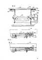
图4是一个含有图3所示系统并包括体现本发明的粒子收集和清除系统的激光焊接装置的透射图;Figure 4 is a perspective view of a laser welding apparatus incorporating the system shown in Figure 3 and including a particle collection and removal system embodying the present invention;

图5和图6分别是粒子收集和清除系统的平面图和侧视图;Figures 5 and 6 are plan and side views, respectively, of the particle collection and removal system;

图7是导管闭锁系统和构成粒子收集和清除系统一部分的气体收集导管的平面图;Figure 7 is a plan view of the duct lockout system and the gas collection duct forming part of the particle collection and removal system;

图8是沿图7的线8-8截取的导管闭锁系统的侧视、剖面图;Figure 8 is a side, cross-sectional view of the catheter lockout system taken along line 8-8 of Figure 7;

图9是沿图8的线9-9截取的导管闭锁系统和气体收集导管的俯视、剖面图;Figure 9 is a top, cross-sectional view of the conduit lockout system and gas collection conduit taken along line 9-9 of Figure 8;

图10是沿图8的线10-10截取的气体收集导管的俯视、剖面图;Figure 10 is a top, cross-sectional view of the gas collection conduit taken along line 10-10 of Figure 8;

图11是沿图7的线11-11截取的导管闭锁系统的侧视、部分剖面图;Figure 11 is a side, partial cross-sectional view of the catheter lockout system taken along line 11-11 of Figure 7;

图12是沿图7的线12-12截取的导管闭锁系统的部分剖面图;Figure 12 is a partial cross-sectional view of the catheter lockout system taken along line 12-12 of Figure 7;

图13是沿图4的线13-13截取的激光焊接装置的焊接箱的侧视、部分剖面图;Fig. 13 is a side view, partial cross-sectional view of the welding box of the laser welding apparatus taken along line 13-13 of Fig. 4;

图14和图15是具有一块密封板的箱密封系统的剖面侧视图,分别示出密封垫处于密封位置和非密封位置。Figures 14 and 15 are cross-sectional side views of a tank sealing system having a sealing plate, showing the gasket in sealing and non-sealing positions, respectively.

现在首先参考图1,在此说明的并且通常用参考数字10表示的核燃料系统是一个独立单元,它包括顶端喷嘴12,底端喷嘴14,在喷嘴12和14之间纵横排列的核燃料棒18的方阵,横向支撑燃料棒并彼此平行间隔开的燃料棒格栅16,以及在核燃料棒18的方阵内选定位置上的控制棒(未标出)。喷嘴12和14,燃料棒格栅16和控制棒导向套管(未标出)形成支撑燃料棒18和控制棒的框架。Referring first now to FIG. 1, the nuclear fuel system illustrated herein and generally indicated byreference numeral 10 is a self-contained unit comprisingtop nozzles 12,bottom nozzles 14, nuclear fuel rods 18 arranged criss-cross betweennozzles 12 and 14. The array,fuel rod grids 16 transversely supporting the fuel rods and spaced parallel to each other, and control rods (not shown) at selected positions within the array of nuclear fuel rods 18 .Nozzles 12 and 14,fuel rod grid 16 and control rod guide bushings (not shown) form a framework for supporting fuel rods 18 and control rods.

体现本发明的精密激光焊接装置特别适用于制造如在图2A到2C中所示格栅16那样的燃料棒格栅。正如平面图所示,燃料棒格栅16近似一个正方形结构,它的周边是四片端部通过角缝焊接30连在一起的外格栅片22。大量内格栅片20形成一个有确定格子的鸡旦箱状结构,这些格子供燃料棒18和控制棒导向套管贯穿通过。相互交叉的内格栅片20具有在交叉点,例如在24,形成的余缝,使交叉的内格栅片20相咬合,在每个交叉点24完成的交叉焊接32又使内格栅片相互连接。每个内格栅片20在其各端部都有一对翼片26,它们被安装在外格栅片22形成的相应槽28中,并通过沿上、下排翼片26和槽28完成的槽和翼片焊接34加以固定。用于控制棒导向套管(未示出)的套筒36安放在格栅16的一个表面上,每个套筒36都安置在内格栅片20的边缘部分形成的凹槽38中,并通过切口线焊接40固定在内格栅片上。体现本发明的激光焊接装置适宜执行一系列控制焊接操作以完成焊接30、32、34和40。The precision laser welding apparatus embodying the present invention is particularly useful in the manufacture of fuel rod grids such as thegrid 16 shown in Figures 2A to 2C. As shown in the plan view, thefuel rod grid 16 is approximately a square structure, and its periphery is fourouter grid sheets 22 whose ends are joined together byfillet welds 30 . A large number ofinner grid sheets 20 form a box-like structure with defined grids for the fuel rods 18 and control rod guide sleeves to pass through. The intersectinginner grid sheets 20 have at intersection points, for example at 24, a surplus seam formed to engage the intersectinginner grid sheets 20, and thecross welding 32 completed at eachintersection point 24 makes the inner grid sheet interconnected. Eachinner grid sheet 20 has a pair offins 26 at each end thereof, which fit intocorresponding slots 28 formed in theouter grid sheet 22 and pass through the slots completed along the upper and lower rows offins 26 andslots 28. Andfin welding 34 is fixed.Sleeves 36 for control rod guide bushings (not shown) are seated on one surface of thegrid 16, eachsleeve 36 being seated in agroove 38 formed in an edge portion of theinner grid sheet 20, and It is fixed on the inner grid sheet byincision line welding 40 . A laser welding apparatus embodying the present invention is adapted to perform a series of controlled welding operations to completewelds 30, 32, 34 and 40.

如图2B和2C所示,在内格栅片20上有很多弹性销44和间隔销46,它们凸出在各个格栅格子上,对贯穿其中的核燃料棒18提供横向支撑,正如人们在这个技术领域中所知道的那样。As shown in Figures 2B and 2C, there are a lot ofelastic pins 44 andspacer pins 46 on theinner grid sheet 20, which protrude from each grid grid to provide lateral support to the nuclear fuel rods 18 running through it, as people in this known in the art.

排定各种焊接操作程序的具体方式并不属于本发明的范畴,所以将不在此作进一步的说明。只要知道在每次这种焊接操作后,所焊接的燃料棒格栅被重新定位和/或者激光束的焦点依据下次所要进行的具体类型的焊接而变化就足够了。The specific way of scheduling various welding operation programs does not belong to the scope of the present invention, so no further description will be given here. It is sufficient to know that after each such welding operation, the fuel rod grid being welded is repositioned and/or the focus of the laser beam is changed depending on the specific type of welding to be performed next time.

在这里,本发明申请的焊接装置可以使用一个诸如图3简要说明的激光系统,通常用参考数字102表示。激光系统102连续发射一束可控能量的激光169,并精确地定位每个工件,即格栅16,並控制释放适量的惰性气体,如氩气,进入一对在其中进行激光焊接的焊接箱108a和108b中。每个工件通过与焊接箱108a和108b其中之一有关的定位舱106a或106b(见图4)被依次移动到它的各个焊接位置,焊接箱108a和108b用于安放工件和建立一个环境,即一种惰性气体的气氛,从而能在其中进行激光焊接。Here, the welding apparatus of the present application may use a laser system such as that schematically illustrated in FIG. 3, generally indicated byreference numeral 102. Thelaser system 102 continuously emits a beam of laser light 169 with controllable energy, and accurately positions each workpiece, that is, thegrid 16, and controls the release of an appropriate amount of inert gas, such as argon, into a pair of welding boxes in which laser welding is performed 108a and 108b. Each workpiece is sequentially moved to its respective welding position through a positioning cabin 106a or 106b (see FIG. 4 ) associated with one of thewelding boxes 108a and 108b, which are used to place the workpiece and establish an environment, i.e. An atmosphere of inert gas in which laser welding can be performed.

激光系统102可以采用雷桑(Raytheon)制造的型号SS500的那种类型。它包括一个由掺钕钇铝石榴石晶体(Nd:YAG)激光构成的激光棒170和一对安装在高效率激光头中的直线氪(Krypton)闪光灯186。激光头包括安装在激光棒170两端的全反射镜182和部分反射镜184。安装在激光棒170如全反射镜182之间的腔内光闸188可有选择地加以控制,以便依据完成激光焊接所需要的能量释放出可供选择数目的激光脉冲。激光头实现积木化结构,可使所有光学元件,包括激光棒170,激励灯186和反射镜182与184的更换即简单又互不干扰。闪光灯186及其端部接头实行全长水冷。灯触发通过激励腔体为激励灯186的并联脉冲作准备。Laser system 102 may be of the type manufactured by Raytheon, model SS500. It consists of alaser bar 170 constructed of a neodymium-doped yttrium aluminum garnet crystal (Nd:YAG) laser and a pair of linear Kryptonflash lamps 186 housed in a high efficiency laser head. The laser head includes atotal reflection mirror 182 and apartial reflection mirror 184 installed at both ends of thelaser rod 170 . Anintracavity shutter 188 mounted betweenlaser bars 170 such astotal reflection mirrors 182 can be selectively controlled to deliver a selectable number of laser pulses depending on the energy required to complete the laser weld. The laser head realizes a building block structure, so that all optical components, including thelaser rod 170, theexcitation lamp 186 and thereflectors 182 and 184, can be easily replaced without interfering with each other. Theflash lamp 186 and its end fittings are water cooled throughout. Lamp triggering provides for a parallel pulse of energizinglamp 186 through the energizing cavity.

一个适当的趋动机构192可使放泄光闸190在第一位置(图中实线表示)和图中用虚线表示的第二位置之间移动,在第一位置上,当更换焊接箱108内的工件时,引导激光束169沿转向轨迹196传输并射到光束吸收器194上;在第二位置上,允许光束169通过扩束透镜系统198聚焦在光束导向装置上,此装置包括一个可移动光束转向反射镜172和一个固定反射镜174。当转向反射镜172位于阻断激光束169的位置时,光束沿轨迹178a转向到反射镜176a上,并且垂直向下射入激光聚焦透镜系统204,此系统把激光束169沿轨迹178a聚焦在焊接箱108a内的工件上,即燃料棒格栅16上。由聚焦透镜202和透镜支托管200构成的激光聚焦透镜系统204,可通过与此相联的Z轴激光系统222(见图4)直线定位。当转向反射镜172,例如通过一个直线电动马达(未标出),从它的激光阻断位置移动到非阻断位置时,激光束169射到固定反射镜174上,并且沿轨迹178b反射到一个反射镜176b上,反射镜176b引导光束射向焊接箱108b。Asuitable actuation mechanism 192 can make thedischarge shutter 190 move between a first position (shown in solid lines among the figures) and a second position shown in broken lines in the figures, in the first position, when replacing thewelding box 108 When the workpiece in the guide laser beam 169 is transmitted along thesteering track 196 and hits the beam absorber 194; in the second position, the beam 169 is allowed to focus on the beam guide device through the beamexpander lens system 198, which includes an adjustable The moving beam turns to amirror 172 and afixed mirror 174 . When turningreflector 172 is positioned at the position of blocking laser beam 169, light beam turns to on the reflector 176a along track 178a, and injects laserfocusing lens system 204 vertically downwards, and this system focuses laser beam 169 along track 178a on welding On the workpiece in thebox 108a, that is, on thefuel rod grid 16. The laserfocusing lens system 204 composed of the focusinglens 202 and thelens support tube 200 can be linearly positioned by a Z-axis laser system 222 (see FIG. 4 ) connected thereto. When thesteering mirror 172 is moved from its laser blocking position to the non-blocking position, such as by a linear electric motor (not shown), the laser beam 169 impinges on thefixed mirror 174 and is reflected along the trajectory 178b to On one mirror 176b, the mirror 176b directs the light beam to thewelding box 108b.

如图4所示,激光系统102安装在相对定位舱106a和106b调准位置上的主框架122上,一经与激光系统102调准,就使两个定位舱相对主框架122和安装在其上的激光系统102固定位置。主框架122由一块顶板142和一块底板(未标出)组成,均焊接成矩型管的框架。顶板142被加工成平面,对安装在其上的系统部件提供一个参考表面。As shown in Figure 4, thelaser system 102 is installed on themain frame 122 on the aligned position relative to the positioning cabins 106a and 106b. Thelaser system 102 is fixed in position. Themain frame 122 is made up of atop plate 142 and a bottom plate (not shown), all welded into the framework of rectangular tubes.Top plate 142 is machined flat to provide a reference surface for system components mounted thereon.

如图4所示,每个定位舱106a和106b中都装有一个滑动平台262,通过一对固定在滑动平台下表面、并可在轴台282上滑动的支撑轴278作直线运动,这样安排是使滑动平台262和位于其上的焊接箱108从有关的定位舱106中滑进滑出。每个焊接箱108都安装在一个X-Y平台241上,而每个X-Y平台241又安装在一个X-Y定位系统288上,以使焊接箱108最好是在一个计算机(未标出)的控制下,沿X轴和Y轴做增量移动。每个定位舱106又包括一个顶板156,它与有关的焊接箱108的间隔很近,并可做为一个密封板,就象本文后面将要说明的那样。As shown in Figure 4, a sliding platform 262 is housed in each of the positioning cabins 106a and 106b, and a pair of support shafts 278 fixed on the lower surface of the sliding platform and capable of sliding on the pillow block 282 make a linear motion. It is to make the sliding platform 262 and thewelding box 108 located thereon slide in and out from therelevant positioning cabin 106 . Eachwelding box 108 is all installed on an X-Y platform 241, and each X-Y platform 241 is installed on an X-Y positioning system 288, so thatwelding box 108 is preferably under the control of a computer (not shown), Incremental movement along the X and Y axes. Eachpositioning module 106 also includes atop plate 156 which is closely spaced from the associated weldedbox 108 and which acts as a sealing plate as will be described later herein.

运动支架140用于相对主框架122的参考表面,更准确地说是相对焊接箱108a和108b内的工件,来定位激光系统102。含有激光棒170(见图3)的激光头罩166安装在一个机械加工平面度很好的光学加工平板168上,该平板上还安装有可移动的光束转向反射镜172(见图3)及其趋动器(未标出),以及由反射镜174、176a和176b构成的固定光束换向器。Thekinematic carriage 140 is used to position thelaser system 102 relative to the reference surface of themain frame 122, and more specifically relative to the workpieces within thewelding boxes 108a and 108b. Thelaser head cover 166 that contains laser rod 170 (seeing Fig. 3) is installed on the optical processingflat plate 168 that a mechanical processing flatness is fine, also is installed on this flat plate movable light beam steering reflector 172 (seeing Fig. 3) and Its actuator (not shown), and a fixed beam diverter formed bymirrors 174, 176a and 176b.

如上所述,每个焊接箱103可从与它有关的定位舱106中撤出以便从中拿走已经焊接完毕的燃料棒格栅16,并更换一个需要焊接的新格栅16。因此,图3和图4表明,箱108b的位置便于新的燃料棒格栅16放入,把格栅16安装于一个可转动的夹具242(见图3)上,尔后,滑动平台262与装在其上的焊接箱108一起再次移进定位舱106中。从图4可知,每个焊接箱108都有一个与密封板156的间隔较小的最上层凸缘。当激光焊接系统工作时,将惰性气体,例如氩气经可转动夹具242中的气口(未标出)和安装在焊接箱108底部的扩散板(未标出)引入焊接箱108内。在焊接箱108重新放入与其相关的定位舱106后,增加进入焊接箱108中的氩气流速率,以便通过在焊接箱上凸缘和密封板下表面之间形成的狭窄空间,净化焊接箱108中的空气和排除湿气。通过上述狭窄空间的氩气流归入作为排气压力通风系统和支撑座的主框架122上的一个大开口(未标出)。如图5和图6所示,输送管喷嘴329在由主框架122确定的压力通风系统内产生一个负压,因而使氩气通过过渡输送管328和排气管道258,从压力通风系统中排放到装有激光焊接装置的建筑物的外部。As mentioned above, each welding box 103 can be withdrawn from its associatedpositioning chamber 106 to remove thefuel rod grid 16 which has been welded therefrom and replace it with anew grid 16 which needs to be welded. Therefore, Fig. 3 and Fig. 4 show that the position ofbox 108b is convenient for putting in newfuel rod grid 16, andgrid 16 is installed on a rotatable clamp 242 (see Fig. Thewelding box 108 on it moves into thepositioning cabin 106 again together. As can be seen from FIG. 4, each weldedbox 108 has an uppermost flange spaced from the sealingplate 156 at a smaller distance. When the laser welding system is working, an inert gas such as argon is introduced into thewelding box 108 through a gas port (not shown) in therotatable fixture 242 and a diffuser plate (not shown) installed at the bottom of thewelding box 108 . After thewelding box 108 is relocated to its associatedpositioning bay 106, the rate of argon flow into thewelding box 108 is increased to purge thewelding box 108 through the narrow space formed between the welding box upper flange and the lower surface of the sealing plate air and remove moisture. The argon flow through the narrow space is directed to a large opening (not shown) in themain frame 122 which serves as the exhaust plenum and support base. As shown in Figures 5 and 6, thedelivery pipe nozzle 329 creates a negative pressure within the plenum defined by themain frame 122, thereby causing the argon gas to pass through thetransition delivery pipe 328 and theexhaust duct 258 to be discharged from the plenum To the exterior of buildings equipped with laser welding equipment.

在安装格栅时进入焊接箱108中的空气和湿气得到净化和排除之前,氩气将以较高的速率连续流动。焊接箱108内放有连续监控箱内环境的一个湿度传感器和一个氧气检测器(未标出)。当湿度和氧气达到预定标准时,激光焊接即可开始,在焊接过程中,氩气被不间断地送入焊接箱108内,但流动速率较小。The argon gas will continue to flow at a relatively high rate until the air and moisture entering theweld box 108 when the grid is installed is purged and removed. A humidity sensor and an oxygen detector (not shown) are placed in thewelding box 108 to continuously monitor the environment inside the box. When the humidity and oxygen reach the predetermined standard, laser welding can start. During the welding process, argon gas is continuously fed into thewelding box 108, but the flow rate is relatively small.

正如本文最初说明的那样,激光焊接使工件产生被清除的粒子物质,它们夹杂在惰性气体流中,还会沉积,形成沉淀。参考图4到图12,下面阐述依据本发明所提供的有关粒子收集和清除系统的一个优选的实施例。As originally stated in this article, laser welding produces particulate matter that is removed from the workpiece, entrained in the inert gas flow, and deposited, forming deposits. Referring to FIG. 4 to FIG. 12, a preferred embodiment of the particle collection and removal system provided by the present invention is described below.

从图4得知,粒子收集系统236包括一对压缩空气趋动的箱密封系统244a和244b,这两个系统分别通过密封支撑系统415a或415b安装在焊接箱108其中之一的开口附近。如下所述,每个箱密封系统244可在每次焊接操作期间密封有关的焊接箱108,使其进入与粒子收集和清除系统的流体流动交换状态。As seen in FIG. 4, theparticle collection system 236 includes a pair of compressed air actuated box seal systems 244a and 244b mounted adjacent the opening of one of the weldedboxes 108 via aseal support system 415a or 415b, respectively. As described below, eachtank sealing system 244 may seal the associatedweld tank 108 into fluid flow communication with the particle collection and removal system during each welding operation.

启动箱密封系统244,使焊接箱108密封到粒子收集系统236上,尔后,氩气被引入箱中以维持箱内适宜的加工环境,并且收集和清除在焊接过程中产生的诸如锆合金(Zircaloy)细屑那样的粒子。氩气与掺杂在其中的锆合金细屑一起,通过各个焊接箱的上开口,从各个箱中排出,进入有关的气体收集导管240a或240b(见图8和图9),通过收集导管进入排气系统248,排气系统248包括成套的管道302、304和连接在导管254上的250、252,导管254与粒子清除系统256相耦接,清除系统用于接收掺有锆合金细屑的氩气,並把它们排放进一个盛放废物的系统。图5和图6表明,粒子清除系统256与排气管道258相耦接,氩气通过排气管道258,被排放到装有激光焊接系统的建筑物外面的大气中。与焊接箱108a和108b(见图4)相连的是透镜密封罩246a和246b,密封罩支配激光聚焦透镜系统204a和204b,並且构成相关的各气体收集导管240a和240b的外壳。气体收集导管240a和240b分别与导管闭锁系统260a或260b相连接,以便相对密封板156a或156b分别固定气体收集导管240a或240b,並且把有关的排气管302与304分别耦接到气体收集导管240a或240b上。Thebox sealing system 244 is activated to seal thewelding box 108 to theparticle collection system 236, after which argon gas is introduced into the box to maintain a suitable processing environment in the box and collect and remove particles such as zirconium alloy (Zircaloy ) particles like fines. Argon gas, together with the zirconium alloy fines doped therein, passes through the upper opening of each welding box, is discharged from each box, enters the relevantgas collection duct 240a or 240b (see Figures 8 and 9), and enters through the collectionduct Exhaust system 248.Exhaust system 248 includes a complete set ofpipes 302, 304 and 250, 252 connected toconduit 254.Conduit 254 is coupled toparticle removal system 256 for receiving particles mixed with zirconium alloy fines. argon and vent them into a waste-holding system. Figures 5 and 6 show that theparticle removal system 256 is coupled to anexhaust duct 258 through which argon gas is exhausted to the atmosphere outside the building in which the laser welding system is installed. Connected towelding boxes 108a and 108b (see FIG. 4) arelens enclosures 246a and 246b which govern laser focusing lens systems 204a and 204b and form housings for the associated respectivegas collection conduits 240a and 240b.Gas collection conduits 240a and 240b are connected toconduit lockout systems 260a or 260b, respectively, to securegas collection conduits 240a or 240b relative to sealingplates 156a or 156b, respectively, and to couple associatedexhaust pipes 302 and 304, respectively, to the gas collection conduits. 240a or 240b.

如上所述,排气系统248可用于清除来自气体收集导管240a和240b的惰性气体以及掺杂在其中的锆合金细屑,而收集导管240a和240b分别与焊接箱108a和108b相联系,每个收集导管都通过两节刚性排气管302、304和两节软排气管250、252与导管254相耦接。刚性排气管302和304可与和它们有关的气体收集导管240脱离耦接,以便允许取下收集导管240并清洗锆合金细屑,而软排气管250和252可使刚性管302和304为此目的作直线移动。As noted above,exhaust system 248 may be used to remove inert gas and zirconium alloy fines doped therein fromgas collection conduits 240a and 240b, which are associated withwelding boxes 108a and 108b, respectively, each The collection conduits are coupled to theconduit 254 through two sections ofrigid exhaust pipes 302, 304 and two sections offlexible exhaust pipes 250, 252.Rigid exhaust tubes 302 and 304 can be decoupled from their associatedgas collection conduits 240 to allow removal ofcollection conduits 240 and cleaning of zirconium alloy fines, whilesoft exhaust tubes 250 and 252 allowrigid tubes 302 and 304 Linear movement is made for this purpose.

导管254与粒子清除系统256相耦接,以便使锆合金细屑或粒子从惰性气体中清除出去并排放进一个污物管或废物清除系统。导管254包括一个舌阀306,它能以一个铰链308为轴运动,从一个关闭位置,如图6中实线所示,移到一个开启位置,如图中虚线所示,并且舌阀306可以被一个适当的趋动机构310所启动。Conduit 254 is coupled toparticle removal system 256 for removing zirconium alloy fines or particles from the inert gas to a waste line or waste removal system.Conduit 254 comprises atongue valve 306, and it can move with ahinge 308 as axis, from a closed position, shown in solid line among Fig. 6, moves to an open position, shown in dashed line among the figure, andtongue valve 306 can Actuated by anappropriate actuator 310.

携带锆合金细屑的氩气通过湿法洗涤器316,进入粒子清除系统256,如图6所示,湿法洗涤器包括一个与进水口312相连接的文氏喷嘴314,进入进水口312的水被喷成雾状用以“清洗”氩气。进气口导管320把氩气引入水阀过滤系统318内,这个过滤系统包括一连串细网过滤器,可提供洗去锆合金细屑的连续水流。湿法洗涤器316和水网过滤器318可以采用纽约法明代尔(Farmingdale)的Heat    Systems,Ultrasonics公司制造的型号分别为HSM2RCMV和MYSTAIRE的产品。清除了锆合金细屑的氩气通过连接导管322和326,由排气喷嘴324吸入,并通过排气导管258排出。The argon gas carrying zirconium alloy fines passes through thewet scrubber 316 and enters theparticle removal system 256. As shown in FIG. Water is sprayed as a mist to "clean" the argon.Inlet conduit 320 introduces argon gas into watervalve filter system 318, which includes a series of fine mesh filters that provide a continuous flow of water to wash away zirconium alloy fines.Wet scrubber 316 and waternet filter 318 can adopt the Heat Systems of Farmingdale, New York (Farmingdale), and the models manufactured by Ultrasonics are respectively HSM2RCMV and MYSTAIRE products. Argon gas cleaned of zirconium alloy fines passes through connectingconduits 322 and 326 , is sucked in byexhaust nozzle 324 , and is exhausted throughexhaust conduit 258 .

有时,从焊接箱中排出的氩气并未被迫进入有关的导管240,因为这种氩气比空气重,所以它将下沉并落入主框架122(图4)中的大开口(未标出),进入由框架所确定的排气压力通风系统。氩气从这个通风系统被通风道风箱329吸到与排气导管258相接的通风道328中。Sometimes the argon exhausted from the welding box is not forced into the associatedconduit 240, since this argon is heavier than air, it will sink and fall into the large opening (not shown) in the main frame 122 (Fig. 4). marked), into the discharge plenum defined by the frame. Argon gas is drawn from this ventilation system by a duct bellows 329 into theduct 328 which joins theexhaust duct 258 .

现在参考图7、图8和图9,对于气体收集导管240和耦接管302与304来说,导管闭锁系统260a和260b其中之一的结构和工作,将作为它们的代表在此加以说明。可以这样理解,当从激光焊接系统中清除锆合金细屑时,它们中的一些将被截留在气体收集导管240内,因此需要进行周期性清洗。正如图8特意指出的那样,气体收集导管240位于透镜密封罩246的内部,而导管也有一个开口用于密封安放激光聚焦透镜系统204。采用一个槽键358部分固定气体收集导管240,槽键固定在透镜密封罩246内,并安装于气体收集导管240的导槽360中,以便把导管240正确地定位在贯穿密封板156的导管开口364内。同样如图8所示,气体收集导管240包括一个下部导管段368和一个上部导管段370,这两个导管段一起形成气体收集导管240。在板156中的导管开口364具有一个与下部导管段368的凸缘相结合的凹槽366,以便通过导管240和激光聚焦透镜系统204调节中心开口367。Referring now to FIGS. 7, 8 and 9, the structure and operation of one of theconduit lockout systems 260a and 260b, representative of thegas collection conduit 240 andcoupling tubes 302 and 304, will be described herein. It will be appreciated that when zirconium alloy fines are removed from the laser welding system, some of them will become trapped within thegas collection conduit 240 and thus require periodic cleaning. As specifically pointed out in FIG. 8 , thegas collection conduit 240 is located inside thelens enclosure 246 , and the conduit also has an opening for sealing the laser focusinglens system 204 . Thegas collection conduit 240 is partially secured by a slotted key 358 which is secured within thelens enclosure 246 and fits in thechannel 360 of thegas collection conduit 240 to properly position theconduit 240 at the conduit opening through theseal plate 156 within 364. As also shown in FIG. 8 , thegas collection conduit 240 includes alower conduit segment 368 and anupper conduit segment 370 which together form thegas collection conduit 240 .Conduit opening 364 inplate 156 has agroove 366 that engages the flange oflower conduit section 368 to accommodatecentral opening 367 throughconduit 240 and laser focusinglens system 204 .

气体收集导管240被放松地锁定在密封板156的适当位置上,并且通过导管闭锁系统260,分别与刚性排气管302和304相耦接,闭锁系统260包括一对枢轴支撑的闭锁杆376a和376b,以及一个闭锁安装板338。图7示出闭锁安装板338在第一位置或闭锁位置上,而图9示出此板在第二位置或非闭锁位置上,闭锁安装板338可通过一个趋动马达348在这两个位置之间移动,马达348通过趋动螺旋机构350机械耦接到闭锁安装板338上,趋动螺旋机构350可提供机械推进,将趋动马达348的转动输出转换成位于闭锁安装板338上与垫块342相连接的活塞352的直线运动。正如图7明确指出的那样,闭锁安装板338的运动通过通过导销344a、344b和344c被控制在上述第一和第二位置之间,这些导销固定在密封板156上,分别被约束在由闭锁安装板338中形成的细长导槽346a、346b和346c中。Gas collection conduit 240 is loosely locked in place onseal plate 156 and is coupled torigid exhaust conduits 302 and 304, respectively, byconduit latching system 260, which includes a pair of pivotally supported latching levers 376a. and 376b, and alatch mounting plate 338. Figure 7 shows thelatch mounting plate 338 in the first or latched position, while Figure 9 shows the plate in the second or unlatched position, thelatch mounting plate 338 can be moved between these two positions by anactuator motor 348 Themotor 348 is mechanically coupled to thelock mounting plate 338 through thedrive screw mechanism 350. Thedrive screw mechanism 350 can provide mechanical propulsion, and convert the rotational output of thedrive motor 348 into a position on thelock mounting plate 338 and thepad Block 342 is connected to the linear movement ofpiston 352 . As clearly indicated in FIG. 7, the movement of thelatch mounting plate 338 is controlled between the above-mentioned first and second positions byguide pins 344a, 344b and 344c, which are fixed to the sealingplate 156 and are respectively constrained in Inelongated guide slots 346 a , 346 b and 346 c formed inlatch mounting plate 338 .

两个闭锁杆376a和376b分别通过枢轴销378a和378b枢轴支撑在密封板156上,每个销都在离闭锁杆两端有段距离的某一点枢轴支撑与其相关的闭锁杆。每个闭锁杆376a或376b在其一端邻近处都有一个内向锁定抓手386a或386b,它们穿过在透镜密封罩246上的开口387a或387b,与在气体收集导管240中的定位槽356a或356b相咬合(也参见图4和图9);每个闭锁杆在其另一端邻近处都枢轴连接在闭锁安装板338上,其方式是使闭锁安装板338能向相反的两个方向移动从而驱动锁定杆的锁定抓手386分别移进和移出气体收集导管240中的定位槽356a或356b的锁定咬合,在每个闭锁杆376和闭锁安装板338之间的枢轴连接是由滚轴382a或382b以及细长的凸轮槽384a或384b形成的,这种滚轴位于闭锁安装板338上的支撑架380a或380b的两个臂381(见图11)之间,并由其转动支撑;而凸轮槽384a和384b位于两个支撑臂381之间延伸的闭锁杆376的一个端部,並与滚轴382相互配合。Two latch levers 376a and 376b are pivotally supported onseal plate 156 bypivot pins 378a and 378b respectively, each pin pivotally supporting its associated latch lever at a point some distance from the ends of the latch lever. Each locking rod 376a or 376b has aninward locking gripper 386a or 386b adjacent one end thereof, and they pass through anopening 387a or 387b in thelens seal cover 246 and align with apositioning groove 356a or 387b in thegas collection conduit 240. 356b interlocking (see also Fig. 4 and Fig. 9); each latch lever is all pivotally connected on thelatch mounting plate 338 adjacent its other end, in such a way that thelatch mounting plate 338 can move in two opposite directions The locking fingers 386 of the locking levers are driven into and out of the locking engagement of thedetents 356a or 356b, respectively, in thegas collection conduit 240. The pivot connection between each lockinglever 376 and thelocking mounting plate 338 is provided by a roller. 382a or 382b andelongated cam groove 384a or 384b, this roller is located between the two arms 381 (see Figure 11) of thesupport frame 380a or 380b on thelock mounting plate 338, and is supported by it for rotation; Thecam grooves 384 a and 384 b are located at one end of the lockingrod 376 extending between the twosupport arms 381 and cooperate with the roller 382 .

这样,当期望把气体收集导管240闭锁在密封板156上时,给趋动马达348通电,使闭锁安装板338运动到左边,如图7、8和9所示,从而使两个闭锁杆376从图9所示的位置错状趋动到图7所示的实线位置,这样即可使闭锁杆的锁定抓手386a和386b与气体收集导管240中的定位槽356a和356b相咬合,把收集导管240锁在密封板156上。另外,闭锁安装板338的这种运动,使安装在其端部的,方向朝着气体收集导管240的磨损垫354与同样在导管上形成的相应定位槽356c相咬合。当期望开锁或解脱气体收集导管240,以便把它取下和清洗时,可给趋动马达348通电,使闭锁安装板338向相反的方向运动,即从图7所示的位置移至图9所示的位置,因而定位或锁定抓手386a、386b和磨损垫354即可从气体收集管240的定位槽356a、356b和356c中撤出。In this way, when it is desired to lock thegas collection conduit 240 on the sealingplate 156, thedrive motor 348 is energized to move thelocking mounting plate 338 to the left, as shown in FIGS. From the position shown in FIG. 9 to the solid line position shown in FIG. 7, the locking handles 386a and 386b of the locking lever can be engaged with thepositioning grooves 356a and 356b in thegas collection conduit 240, and theCollection conduit 240 is locked to sealplate 156 . Additionally, such movement of thelatch mounting plate 338 causes awear pad 354 mounted on its end, directed toward thegas collection conduit 240, to engage acorresponding detent 356c also formed in the conduit. When it is desired to unlock or disengage thegas collection conduit 240 so that it can be removed and cleaned, theactuator motor 348 can be energized to move thelock mounting plate 338 in the opposite direction, i.e. from the position shown in FIG. 7 to the position shown in FIG. 9 In the position shown, the positioning or lockingfingers 386a, 386b and thewear pad 354 can be withdrawn from thepositioning slots 356a, 356b and 356c of thegas collection tube 240.

图8、图9和图10最清楚地说明了气体收集导管240。它被设计成不仅便于脱离密封板156,而且在放回密封板156的导管开口364之前,便于拆卸和清洗。如前所述,气体收集导管240具有一个下部导管段368(图8)和一个上部管段370。从图9可知,下部导管段368中已形成大量入射口372a、372b、372c和372d,其中有一些,如入射口372a和372b,通入第一个过渡腔374a内并与其相连(见图10),而剩下的入射口372c和372d通入第二个过渡腔374b内并与其相连。入射口372和过渡腔374a、374b按设计要求,可使通过的气流速度的任何降低减至最小,因而使气体收集导管240中收集的和从气流中沉积下来的粒子物质的量降至最低限度。所以,为保持气流速度基本不变,精心设计了入射口372和过渡腔374的外形,在气流面积的横截面没有显著增加的情况下,把通过入射口372进入的气体平稳地引向并射入一对出射口392a和392b,过渡腔374按设计要求可使入射口372逐渐将弧形、较狭窄的流动外形变为出射口392的圆截面流动外形,此外,每个出、入射口都靠近其中点呈流线型地接到有关的过渡腔374a或374b上,以便使来自入射口372a、372b或372c、372d的气体通路能分别进入出射口392a或392b。Thegas collection conduit 240 is most clearly illustrated in FIGS. 8 , 9 and 10 . It is designed not only for ease of disengagement from theseal plate 156 but also for ease of removal and cleaning before being placed back into the conduit opening 364 of theseal plate 156 . As previously mentioned, thegas collection conduit 240 has a lower conduit section 368 ( FIG. 8 ) and anupper conduit section 370 . As can be seen from Fig. 9, a large number ofinlets 372a, 372b, 372c and 372d have been formed in thelower conduit section 368, and some of them, such asinlets 372a and 372b, lead into thefirst transition cavity 374a and are connected with it (see Fig. 10 ), while the remaininginlets 372c and 372d lead into and connect to the second transition chamber 374b. Theinlet port 372 andtransition chambers 374a, 374b are designed to minimize any reduction in velocity of the gas flow passing therethrough, thereby minimizing the amount of particulate matter collected in thegas collection conduit 240 and deposited from the gas flow . Therefore, in order to keep the airflow velocity basically unchanged, the shapes of theinlet 372 and thetransition chamber 374 are carefully designed to guide and inject the gas entering through theinlet 372 smoothly without increasing the cross-section of the airflow area significantly. A pair ofoutlets 392a and 392b, thetransition chamber 374 can make theinlet 372 gradually change the arc-shaped and narrower flow shape into the circular cross-section flow shape of the outlet 392 according to the design requirements, in addition, each outlet and inlet are close to The center point is streamlined to the associatedtransition chamber 374a or 374b so that the gas passage from theentrance port 372a, 372b or 372c, 372d can enter theexit port 392a or 392b, respectively.

正如图7和图9极好证明的那样,刚性管301a和301b的安装可使它们相对于闭锁安装板338作有限的轴向相对运动。在每个管301a和301b的入口端都有一个环状密封凸缘388a或388b,它们可分别与插孔390a或390b相配合,而插孔分别形成在与有关的出射口392a或392b轴向调准的气体收集导管240中,并具有一个O型环394a或394b。当管301a和301b的凸缘端部完全插入有关的插孔390中时,管301的密封凸缘388a和388b与相应的O型环394a和394b密封接触以防止漏气。As best demonstrated in FIGS. 7 and 9, therigid tubes 301a and 301b are mounted so that they have limited axial relative movement relative to thelatch mounting plate 338. At the inlet end of eachtube 301a and 301b, there is an annular sealing flange 388a or 388b, which can cooperate with theinsertion hole 390a or 390b respectively, and the insertion hole is formed in the axial direction of therelevant outlet 392a or 392b, respectively. The aligned gas is collected inconduit 240 and has an O-ring 394a or 394b. When the flanged ends of thetubes 301a and 301b are fully inserted into the associated receptacle 390, the sealing flanges 388a and 388b of the tube 301 are in sealing contact with the corresponding O-rings 394a and 394b to prevent air leakage.

正如从图9和图12明显看出的那样,每个管301a和301b都由滑动凸缘396a、398a或396b、398b以及固定导块400a、402a或400b、402b滑动支撑在闭锁安装板338上,滑动凸缘固定安装在相应的管301相对的两侧上以轴向间隔定位;而固定导块固定在闭锁安装板338上并可滑动支撑管上的相应滑动凸缘。As is apparent from Figures 9 and 12, eachtube 301a and 301b is slidably supported on alatch mounting plate 338 by a slidingflange 396a, 398a or 396b, 398b and a fixedguide 400a, 402a or 400b, 402b , the sliding flanges are fixedly mounted on the opposite sides of the corresponding tubes 301 to be spaced axially;

正如图9极好证明的那样,滑动管301与刚性排气管302和304相耦接,其耦接方式允许301a和301b滑动,并且使位移弹簧406a和406b滑动,以便在相应的管301的密封凸缘388和有关的导管插孔390中的O型环394彼此咬合时保持密封压力。更准确地说,每个滑动管301上都有一个弹簧固定凸缘404,而每个排气管302和304上都有一个卡圈408,与其相关的一个位移弹簧406(螺旋弹簧)被压紧放入凸缘404和卡圈408之间。在管301的密封凸缘388与O型环394相咬合后仍然发生的管301a和301b的弹性轴向运动的范围,可通过按照在每个管301上的各个凸缘404和相邻导块400、402之间的间隔,比较图7和9而得出。As best demonstrated in FIG. 9 , sliding tube 301 is coupled torigid exhaust tubes 302 and 304 in such a way as to allow sliding of displacement springs 406 a and 406 b and displacement springs 406 a and 406 b to slide in the respective tubes 301 Sealing flange 388 and O-ring 394 in associated conduit receptacle 390 engage each other to maintain sealing pressure. More precisely, there is a spring retaining flange 404 on each slide tube 301, and acollar 408 on eachexhaust tube 302 and 304, a displacement spring 406 (coil spring) associated with it is compressed Fit tightly between flange 404 andcollar 408 . The range of elastic axial movement of thetubes 301a and 301b that still occurs after the sealing flange 388 of the tube 301 engages the O-ring 394 can be determined by the respective flanges 404 and adjacent guide blocks on each tube 301. The spacing between 400, 402 is obtained by comparing FIGS. 7 and 9 .

从图8、图9和图12将得知,两个卡圈408a和408b都分别与调节机构408a或408b相联系,调节机构包括被一个适当的扣钉413(图12)固定在闭锁安装板338上的支撑部件416,一个附加在有关的排气管302或304上的耦接部件412,以及与支撑部件416螺旋啮合的调节器414,这样安排的目的是,调节装置414的转动将使耦接部件412移动,因而调节卡圈408的位置,以相应改变由相应的弹簧406所施加的密封力。这种调节可以随意进行或根据需要偶尔进行以抵偿各滑动管301与O型环394在相应的导管插孔390初始咬合时,相应的滑动管301的残余运动范围出现的变化。It will be known from Fig. 8, Fig. 9 and Fig. 12 that the twocollars 408a and 408b are respectively associated with theadjustment mechanism 408a or 408b, and the adjustment mechanism is fixed on the locking mounting plate by an appropriate pin 413 (Fig. 12). 338 on thesupport member 416, a coupling member 412 attached to therelevant exhaust pipe 302 or 304, and anadjuster 414 that is screw-engaged with thesupport member 416, the purpose of this arrangement is that the rotation of theadjustment device 414 will make The coupling member 412 moves, thereby adjusting the position of thecollar 408 to correspondingly change the sealing force exerted by the corresponding spring 406 . This adjustment can be made at will or occasionally as needed to compensate for variations in the residual range of motion of the respective slide tube 301 upon initial engagement of the respective slide tube 301 with the O-ring 394 in the corresponding catheter receptacle 390 .

现在参考图13、图14和图15,把箱密封系统244a和244b(图4)中的一个作为它们两个的代表加以说明。每个密封系统244基本上都包括一个通常为环状的密封元件428和密封趋动设备418,密封元件428由相应的焊接箱108的顶部凸缘109所支撑,并直接位于密封板156的下部,围绕箱108的开启顶端伸展;而密封趋动设备强迫密封元件428与密封板156的底面进入密封咬合。更确切地说,密封元件428是一个由适当材料,例如充满玻璃的聚四氟乙烯(giass-filled    Teflon),制成的弹性圈;而趋动设备418包括一个适当材料,例如聚氯丁橡胶(neoprene),制成的可膨胀的环状管,它直接位于密封圈428的下部,这样,当趋动设备膨胀时,例如通过一个接管426(图13),即可强迫密封圈428与密封板156的下表面密封咬合,如图15所示。对可膨胀的管418的支撑由一个垫圈414提供,在垫圈的上面具有一个用于安放可膨胀管418的环形凹槽416。垫圈414和密封圈428通过一个环状护圈420和螺栓422固定在支撑圈415上,方法是夹住密封圈428在垫圈414和护圈420的凸缘424之间的内边部位,并且夹住在护圈420和支撑圈415的外凸缘部位之间的垫圈414的内凸缘部位,然后再依次把支撑圈415固定在,例如用螺栓连接,焊接箱的上部凸缘109上。为了使焊接箱108从一个焊接位置移到另一个焊接位置时,相对定位机构288(图4)的摩擦和阻力最小,密封板156最好具有一个抛光的下表面,例如一个抛光的铬表面,而密封趋动管418用压力,例如0.15到0.20大气压膨胀,使密封圈428以适度的力顶压在密封板156的抛光表面上,当然,这足以提供密封圈428和密封板156之间适宜的密封接合。如图14所示,在环状支撑部件415的上表面417和密封板156的下表面之间留有一段狭窄的空间,以便允许焊接箱108很容易地撤至其装料位置,如图4所示的箱108b的位置。Referring now to Figures 13, 14 and 15, one of the tank sealing systems 244a and 244b (Figure 4) will be described as representative of both. Eachsealing system 244 basically includes a generallyannular sealing element 428 supported by thetop flange 109 of the corresponding weldedbox 108 and located directly below the sealingplate 156 and a sealingactuator 418 , Stretches around the open top of thebox 108; and the sealing drive device forces the sealingelement 428 into sealing engagement with the bottom surface of the sealingplate 156. More specifically, sealingelement 428 is an elastomeric ring made of a suitable material, such as glass-filled polytetrafluoroethylene (giass-filled Teflon); andactuator device 418 includes a suitable material, such as neoprene (neoprene), made of expandable annular tube, it is located directly under the sealingring 428, so that when the actuator expands, such as through a connecting tube 426 (Figure 13), the sealingring 428 can be forced to seal The lower surface of theplate 156 is sealingly engaged, as shown in FIG. 15 . Support for theexpandable tube 418 is provided by awasher 414 having anannular groove 416 thereon for receiving theexpandable tube 418 . Thewasher 414 and sealingring 428 are secured to thesupport ring 415 by an annular retainer 420 andbolts 422 by clamping the inner edge of the sealingring 428 between thewasher 414 and the flange 424 of the retainer 420 and clamping Live in the inner flange portion of thegasket 414 between the retainer ring 420 and the outer flange portion of thesupport ring 415, and then thesupport ring 415 is fixed, for example, with bolts, on theupper flange 109 of the welded box in turn. In order to minimize friction and resistance relative to positioning mechanism 288 (FIG. 4) when weldingbox 108 is moved from one welding position to another, sealingplate 156 preferably has a polished lower surface, such as a polished chrome surface, And the sealingdrive tube 418 expands with pressure, such as 0.15 to 0.20 atmospheric pressure, so that theseal ring 428 is pressed against the polished surface of theseal plate 156 with a moderate force. Of course, this is enough to provide a good fit between theseal ring 428 and theseal plate 156. sealed joint. As shown in Figure 14, leave a section of narrow space between theupper surface 417 ofannular support member 415 and the lower surface of sealingplate 156, so that allowwelding box 108 to be withdrawn to its loading position easily, as shown in Figure 4 The location ofbox 108b is shown.

激光焊接装置102的工作基本上包括三个连续进行的过程,即装料、净化和焊接。在完成一个燃料棒格栅16的焊接以后,滑板262与在其上的焊接箱108一起,从相应的定位舱106中撤到装料位置,在此位置上,焊接的燃料棒格栅可以很容易地从箱中取出并装上一个待焊接的新工件。在卸料和重新装料过程中,可能已经沉积在气体收集导管240内的锆合金细屑可通过使启动机构310(图6)关闭舌阀306加以清除。当排气风箱324工作时,导管254内将产生足够的负压,通过气体导管240、排气管302和304、弹性管250和252以及导管254吸入空气。按这种方法吸入的空气将通过排气系统248迅速氧化锆合金细屑,因此减少了锆合金细屑的沉淀可能聚集而后燃烧或爆炸的可能性。The work of thelaser welding device 102 basically includes three continuous processes, namely charging, cleaning and welding. After completing the welding of afuel rod grid 16, the slide plate 262, together with thewelding box 108 thereon, is withdrawn from thecorresponding positioning cabin 106 to the charging position, at this position, the welded fuel rod grid can be easily Easily removed from the box and loaded with a new workpiece to be welded. During unloading and reloading, zirconium alloy fines that may have settled in thegas collection conduit 240 can be removed by causing the actuator mechanism 310 (FIG. 6) to close theflap valve 306. When the exhaust bellows 324 is working, sufficient negative pressure will be generated in theconduit 254 to suck air through thegas conduit 240 , theexhaust pipes 302 and 304 , theelastic pipes 250 and 252 and theconduit 254 . Air drawn in this way will rapidly oxidize the zirconium alloy fines through theexhaust system 248, thereby reducing the likelihood that a deposit of zirconium alloy fines may accumulate and then burn or explode.

下一个待焊的燃料棒格栅放入焊接箱108,而且任何聚集的锆合金细屑已经除去以后,滑板262与放在其上的加料焊接箱108一起回复到定位舱106内,如图4所示。此时,激光焊接装置102开始净化操作,以清除焊接箱108中的空气和湿气。在焊接箱108内能够污染燃料棒格栅焊接的残存空气,例如通过在可转动夹具242(图3和13)中的导管(未标出)和在焊接箱108底部的扩散器(未标出)使一种惰性气体,例如氩气,进入焊接箱108内进行清洗。氩气就这样被以一个较高的速率引入,清洗吸入了空气和湿气的焊接箱108,直至达到预定水平。在清洗过程中,不启动密封圈428,这样,从箱108中溢出的氩气可以通过环状支撑部件415和密封板156之间的空隙排走。The next fuel rod grid to be welded is put into thewelding box 108, and after any accumulated zirconium alloy fines have been removed, the slide plate 262 returns to thepositioning cabin 106 with the chargingwelding box 108 placed thereon, as shown in FIG. 4 shown. At this time, thelaser welding device 102 starts a purge operation to remove air and moisture in thewelding box 108 . Trapped air within theweld box 108 that can contaminate fuel rod grid welding, for example, through ducts (not shown) in the rotatable fixture 242 ( FIGS. 3 and 13 ) and diffusers (not shown) at the bottom of theweld box 108 . ) makes an inert gas, such as argon, enter thewelding box 108 for cleaning. Argon gas is thus introduced at a relatively high rate to purge theweld box 108 of entrained air and moisture until a predetermined level is reached. During the cleaning process, the sealingring 428 is not activated, so that the argon gas overflowing from thetank 108 can be discharged through the gap between theannular support member 415 and the sealingplate 156 .

接着进行焊接,以完成焊接箱108内、放于惰性气体环境中的格栅上的各种槽和翼片焊接34、角缝焊接30和交叉焊接32。在焊接过程中,导管254的舌阀306处于开启位置(图6中的虚线),这样,导管254和焊接箱108中由排气风箱324所形成的负压即可消除,不使氩气从焊接箱108中排出,也不使可导致焊接污染的空气吸入。随着惰性气体不断进入焊接箱108内,箱内氩气氛的压力也不断增加,直到惰性气体从箱的顶部排出,流过气体收集导管240、排气管302和304以及弹性管250、252进入导管254,在这里被排气风箱324吸入可以清除锆合金粒子和通过排气导管258排放氩气的粒子收集系统236中。Welding follows to complete the various slot and tab welds 34, fillet welds 30 and cross welds 32 within theweld box 108 on the grid placed in an inert gas atmosphere. During the welding process, thetongue valve 306 of theconduit 254 is in an open position (dotted line among Fig. 6), like this, the negative pressure formed by the exhaust bellows 324 in theconduit 254 and thewelding box 108 can be eliminated, and the argon gas will not flow from Thewelding box 108 is exhausted, and the air that may cause welding contamination is not sucked in. As the inert gas continues to enter thewelding box 108, the pressure of the argon atmosphere inside the box increases until the inert gas exits the top of the box, flows through thegas collection conduit 240, theexhaust pipes 302 and 304 and theelastic tubes 250, 252 into theConduit 254 , here drawn by exhaust bellows 324 , intoparticle collection system 236 which removes zirconium alloy particles and exhausts argon throughexhaust conduit 258 .

经过一定次数的焊接操作后,气体收集导管240内可能已截留了足够多的锆合金细屑,最好能清洗气体收集导管240,清洗过程如前所述,马达348通电(图7、图8和图9)后,闭锁安装板338运动,使滑管301从气体收集导管240中的插孔390内撤出,与此同时,使闭锁杆376和磨损垫354运动,脱离与导管240的定位槽256的闭锁咬合。现在可以把气体收集导管240从透镜密封罩246中取下,而导管240的两段368和370可以分离,显露出入射口372、过渡腔374和出射口392以利清洗。一旦导管内的锆合金细屑清洗完毕,导管即被重新组装好,再放回到密封板156的导管开口364中去,并通过闭锁系统260锁定在适当的位置上。After a certain number of welding operations, enough zirconium alloy fines may have been trapped in thegas collection conduit 240, and it is preferable to clean thegas collection conduit 240. The cleaning process is as described above, and themotor 348 is energized (Fig. 7, Fig. 8 and FIG. 9 ), thelocking mounting plate 338 moves, so that the slide tube 301 is withdrawn from the insertion hole 390 in thegas collection conduit 240, and at the same time, the lockingrod 376 and thewear pad 354 are moved to break away from the position of theconduit 240 The latching engagement of thegroove 256. Thegas collection conduit 240 can now be removed from thelens enclosure 246, and the twosections 368 and 370 of theconduit 240 can be separated, exposing theinlet port 372,transition chamber 374 and outlet port 392 for cleaning. Once the conduit has been cleaned of zirconium alloy fines, the conduit is reassembled and placed back into conduit opening 364 ofseal plate 156 and locked in place by latchingsystem 260.

Claims (13)

1, employing can produce the device of the light beam processing work of foreign particles material, this device comprises the processing case that is used to lay workpiece to be processed, also comprise and be used for a kind of non-active gas is introduced the processing case so that make the device that keeps suitable processing environment in the case in each process operation, above-mentioned processing case has an opening that allows non-active gas to discharge from case, it is characterized in that: above-mentioned processing case (108) with comprise the have inlet duct particle collection and the scavenge unit (236 of a conduit (240) of (372), 256) relevant, in addition, also with sealing device (156,418,428) relevant, these sealing devices can be disarmed state, allow non-active gas from the processing case, freely to escape by above-mentioned opening, also can be effective status, promptly the above-mentioned inlet duct (372) of the above-mentioned opening of sealing processing case (108) and conduit (240) keeps the mobile contact of fluid, the particulate material that forces non-active gas and be entrained in wherein flows out from the processing case, enters above-mentioned conduit fully.
9, device according to claim 6 or 7, it is characterized in that: support the above-mentioned moving component (338) that divides coupling access equipment (301), it can move between the primary importance and the second place, so that particle scavenge system (256) is couple to the jack apparatus (390 of conduit (240), 392) on, couple with breaking away from socket equipment, above-mentioned conduit can be removed, also with can be operated in locking and conciliate the blocking device (376) that dislocation puts and interrelate, this blocking device can fix on catheter lock on the operating position, releasable and take off conduit again, above-mentioned moveable element (338) and above-mentioned blocking device (376) link in the following manner, promptly moving component (338) move to the first and second above-mentioned positions meanwhile blocking device (376) move to above-mentioned locking respectively and conciliate dislocation and put.
CN 851055671985-07-201985-07-20 Laser beam welding devicePendingCN85105567A (en)

Priority Applications (1)

Application NumberPriority DateFiling DateTitle
CN 85105567CN85105567A (en)1985-07-201985-07-20 Laser beam welding device

Applications Claiming Priority (1)

Application NumberPriority DateFiling DateTitle
CN 85105567CN85105567A (en)1985-07-201985-07-20 Laser beam welding device

Publications (1)

Publication NumberPublication Date
CN85105567Atrue CN85105567A (en)1987-01-21

Family

ID=4794562

Family Applications (1)

Application NumberTitlePriority DateFiling Date
CN 85105567PendingCN85105567A (en)1985-07-201985-07-20 Laser beam welding device

Country Status (1)

CountryLink
CN (1)CN85105567A (en)

Similar Documents

PublicationPublication DateTitle
US4642445A (en)Shielding apparatus for metal processing operations
EP0206027A2 (en)End-of-arm tooling carousel apparatus for use with a robot
US5378898A (en)Electron beam system
JP5389236B2 (en) Ablation method and apparatus
CN100522455C (en) Dry cleaning system using laser
TWI323003B (en)Reactor design to reduce particle deposition during process abatement
US4501949A (en)Movable machining chamber with rotatable work piece fixture
CN105723282B (en)Optical arrangement, in particular plasma light source or EUV lithography apparatus
CN1430243A (en) Online laser wafer seat cleaning device
EP0102835B1 (en)Apparatus and method for laser machining in a non-reactive environment
BE897641A (en)Apparatus for laser processing
CN107717227B (en) A laser narrow gap welding head
JP2011524643A (en) Particle cleaning of optical elements for microlithography
AU2021278997A1 (en)Modular architecture for additive manufacturing
JP6882551B2 (en) A device for generatively producing a three-dimensional object
KR910004963B1 (en) Laser processing equipment
CN1332649A (en)Flame arrester
EP0168673B1 (en)Laser beam welding apparatus
CN85105567A (en) Laser beam welding device
US20230095918A1 (en)Laser processing head having contamination resistance
US3742183A (en)Optical element protection in laser apparatus
FR2702980A1 (en) Recovery device for machining machine
CN115922175A (en)Intelligent welding equipment is used in production of hoist cantilever crane
CN1868614A (en)Purging system having workpiece movement device
JP2000197983A (en) Laser cutting method and laser cutting device

Legal Events

DateCodeTitleDescription
C06Publication
PB01Publication
WD01Invention patent application deemed withdrawn after publication

[8]ページ先頭

©2009-2025 Movatter.jp