CN2938145Y - Structural improvement of light guide plate and liquid crystal display device having the light guide plate - Google Patents
Structural improvement of light guide plate and liquid crystal display device having the light guide plateDownload PDFInfo
- Publication number
- CN2938145Y CN2938145YCN 200620120143CN200620120143UCN2938145YCN 2938145 YCN2938145 YCN 2938145YCN 200620120143CN200620120143CN 200620120143CN 200620120143 UCN200620120143 UCN 200620120143UCN 2938145 YCN2938145 YCN 2938145Y
- Authority
- CN
- China
- Prior art keywords
- light
- guide plate
- light guide
- angle
- liquid crystal
- Prior art date
- Legal status (The legal status is an assumption and is not a legal conclusion. Google has not performed a legal analysis and makes no representation as to the accuracy of the status listed.)
- Expired - Fee Related
Links
- 239000004973liquid crystal related substanceSubstances0.000titleclaimsdescription21
- 238000009792diffusion processMethods0.000claimsdescription10
- 239000012788optical filmSubstances0.000description7
- 239000010408filmSubstances0.000description4
- 238000010586diagramMethods0.000description3
- 230000000694effectsEffects0.000description2
- 238000000149argon plasma sinteringMethods0.000description1
- 230000009286beneficial effectEffects0.000description1
- 238000000034methodMethods0.000description1
Images

Landscapes
- Planar Illumination Modules (AREA)
Abstract
Description
Translated fromChinese技术领域technical field
本实用新型涉及一种导光板结构改良,旨在提供一种可避免大角度光的损失,提高光利用率,并可省去棱镜片及扩散片的设置,以达到薄型化设计的导光板结构改良。The utility model relates to an improved light guide plate structure, which aims to provide a light guide plate structure that can avoid the loss of light at large angles, improve the light utilization rate, and save the setting of prism sheets and diffusion sheets to achieve a thinner design. improved.
背景技术Background technique
一般液晶显示装置(Liquid Crystal Display,LCD)的背光模块(Back Light Unit,BLU)的基本结构组成如图1所示,由导光板(LGP)11、设于导光板11板缘位置的光源12、设于导光板11下方的反射膜片13,以及设于导光板11与液晶面板17之间的光学膜片等组件所构成。The basic structure of the backlight module (Back Light Unit, BLU) of a general liquid crystal display device (Liquid Crystal Display, LCD) is shown in Figure 1. , a
其中,导光板11的主要功能是藉由光散乱原理将光源12入射的平行光转换成平面垂直光,但为了达到散射均光的效果,通常于导光板11与液晶面板17之间所设置的光学膜片,其主要依序由下扩散片14、二棱镜片15以及上扩散片16所组成,以散射均光的效果;各棱镜片15上板面设有棱镜结构151(棱镜结构呈连续锯齿沟槽状),其接收由导光板11及下扩散片14的光线,并经由各棱镜片的棱镜结构151折射后,其光线的发光角度变大,进而使视角变大而令亮度降低。Among them, the main function of the
故亦有如图2所示的液晶显示装置结构,其由导光板(LGP)11、设于导光板11板缘位置的光源12、设于导光板11下方的反射膜片13,以及设于导光板11与液晶面板17之间的光学膜片等组件所构成;其中,该光学膜片主要依序由一逆棱镜片15’以及上扩散片16所组成,其逆棱镜片15’的底面亦设有复数棱镜结构151’,当光线由导光板11射出而进入逆棱镜片15’时,可缩小光线的出光角度,进而缩小视角而令亮度提高。Therefore, there is also a liquid crystal display device structure as shown in Figure 2, which consists of a light guide plate (LGP) 11, a
然而,上述两种液晶显示装置结构,均利用增加数光学膜片的使用,不仅增加了成本,且其各光学膜片的组装,亦会增加该液晶显示装置的厚度,违背了轻、薄、短、小的需求。However, the above-mentioned two liquid crystal display device structures all utilize the use of increasing the number of optical films, which not only increases the cost, but also increases the thickness of the liquid crystal display device in the assembly of each optical film, which violates the lightness, thinness, Short, small needs.
实用新型内容Utility model content
有鉴于此,本实用新型在于提供一种可避免大角度光的损失,提高光利用率,并可省去棱镜片及扩散片的设置,以达到薄型化设计的导光板结构改良,以及一种利用该导光板结构改良的液晶显示装置。In view of this, the utility model is to provide an improved light guide plate structure that can avoid the loss of light at large angles, improve the light utilization rate, and save the setting of the prism sheet and the diffusion sheet to achieve a thinner design. A liquid crystal display device improved by using the structure of the light guide plate.
本实用新型导光板的结构改良的解决手段,是该导光板至少包括有一入光面、一与该入光面相交的底面,以及一与该底面相对的出光面,而光源则设置于对应该入光面的一侧;其中,该出光面及底面分别设有第一、二组切槽,其第一、二组切槽各切槽的截面具有一顶角、一第一斜角及第二斜角,该第一组切槽各切槽中顶角的取值范围是75°~120°,该第二组切槽各切槽中第一斜角的取值范围是35°~55°,以使通过的光线由全反射方式以一定出光角度射出。The solution to the structural improvement of the light guide plate of the utility model is that the light guide plate at least includes a light incident surface, a bottom surface intersecting the light incident surface, and a light exit surface opposite to the bottom surface, and the light source is arranged on the corresponding One side of the light-incident surface; wherein, the light-emitting surface and the bottom surface are respectively provided with first and second sets of cut grooves, and the cross-sections of the first and second sets of cut grooves have a top angle, a first bevel angle and a second set of cut grooves. Two bevel angles, the value range of the apex angle in each groove of the first group of grooves is 75°~120°, the value range of the first bevel angle in each groove of the second group of grooves is 35°~55° °, so that the passing light is emitted at a certain light angle by total reflection.
以及一种液晶显示装置,其至少包含有:And a liquid crystal display device, which at least includes:
一导光板,该导光板至少包括有一入光面、一与该入光面相交的底面,以及一与该底面相对的出光面;A light guide plate, which at least includes a light incident surface, a bottom surface intersecting the light incident surface, and a light exit surface opposite to the bottom surface;
一光源,设置于导光板入光面的一侧;A light source, arranged on one side of the light incident surface of the light guide plate;
一反射片,设置于导光板下方;a reflective sheet arranged under the light guide plate;
一扩散片,设置于导光板上方;A diffusion sheet is arranged above the light guide plate;
一液晶面板,设置于扩散片上方;a liquid crystal panel, arranged above the diffuser;
该出光面及底面分别设有第一、二组切槽,其第一、二组切槽各切槽的截面具有一顶角、一第一斜角及第二斜角,该第一组切槽各切槽中顶角的取值范围是75°~120°,该第二组切槽各切槽中第一斜角的取值范围是35°~55°,以使通过的光线由全反射方式以一定出光角度射出。The light-emitting surface and the bottom surface are respectively provided with first and second groups of cut grooves. The cross-sections of the first and second groups of cut grooves each have a top angle, a first bevel angle and a second bevel angle. The first group of cut grooves The value range of the apex angle in each groove of the groove is 75°~120°, and the value range of the first oblique angle in each groove of the second group of grooves is 35°~55°, so that the light passing through is completely The reflection mode emits light at a certain angle.
本实用新型采用上述结构所达到的有益效果在于:可以得到一种可避免大角度光的损失,提高光利用率,并可省去棱镜片及扩散片的设置,以达到薄型化设计的导光板结构改良,以及一种利用该导光板结构改良的液晶显示装置。The utility model adopts the above-mentioned structure to achieve the beneficial effects: a light guide plate can be obtained which can avoid the loss of light at large angles, improve the utilization rate of light, and save the setting of the prism sheet and the diffusion sheet, so as to achieve a thinner design. The structure is improved, and a liquid crystal display device utilizing the structure improvement of the light guide plate.
附图说明Description of drawings
图1为第一种习用背光模块的结构示意图;FIG. 1 is a structural schematic diagram of the first conventional backlight module;
图2为第二种习用背光模块的结构示意图;FIG. 2 is a schematic structural diagram of a second conventional backlight module;
图3为本实用新型中导光板第一实施例的结构立体图;Fig. 3 is a perspective view of the structure of the first embodiment of the light guide plate in the present invention;
图4为本实用新型中导光板顶角放大的结构示意图;Fig. 4 is a structural schematic diagram of the magnified top angle of the light guide plate in the utility model;
图5为本实用新型中导光板第二实施例的结构示意图;Fig. 5 is a schematic structural view of the second embodiment of the light guide plate in the present invention;
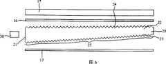
图6为本实用新型中导光板第三实施例的结构立体图。FIG. 6 is a structural perspective view of the third embodiment of the light guide plate in the present invention.
【图号说明】【Description of figure number】
θ 顶角 11 导光板
12 光源 13 反射膜片12
14 下扩散片 15 棱镜片14
151 棱镜结构 15’ 逆棱镜片151 Prism structure 15’ Inverse prism sheet
151’ 棱镜结构 16 上扩散片151'
17 液晶面板 20 导光板17
21 入光面 22 出光面21 Light-
23 底面 30 光源23
24 第一切槽组 25 第二切槽组24 The
具体实施方式Detailed ways
为能使贵审查员清楚本实用新型的结构组成,以及整体运作方式,兹配合图式说明如下:In order to make your examiner understand the structure and composition of the utility model, as well as the overall operation mode, it is described as follows with the drawings:
本实用新型导光板的结构改良,主要针对侧光式背光模块架构中导光板加以改良,如图3所示,其导光板20板端部分为入光面21,其正面部分为出光面22,而相对于出光面22并有入光面21相交的底面23,而光源30设置于对应该入光面21的一侧,其光源30可以为点光源(如发光二极管),使光线得以自该入光面21射入,再由导光板20正面的出光面22射出,以达到光源显示的效果。The structural improvement of the light guide plate of the utility model is mainly aimed at improving the light guide plate in the side-light backlight module structure. As shown in FIG. With respect to the light-emitting
本案的重点在于:该出光面22及底面23设有第一、二组切槽24、25,如图所示的实施例,该第一、二组切槽24、25为V型沟槽的结构,其截面具有一顶角Y、一第一斜角β及第二斜角α,如图4所示,该第一组切槽24各切槽中顶角Y的取值范围是75°~120°,该第二组切槽25各切槽中第一斜角β的取值范围35°~55°,以使通过的光线由全反射方式以一定出光角度射出,可避免大角度光的损失。The key point of this case is that the
另外,该第一、二组切槽24、25可以接续排列的方式设置于导光板20的出光面22及底面23上,如图4所示;亦可如图5所示,各切槽间具有间距,且该间距呈梯度式变化,而光源30可正对于具有间距最大的切槽设置。In addition, the first and second sets of
具体实施时,该液晶显示装置的背光模块结构如图6所示,由导光板20、设于导光板20板缘位置的光源30、设于导光板20下方的反射膜片13,以及设于导光板20与液晶面板17之间的上扩散片16所构成,其光源30的光线由导光板20入光面21进入导光板20,部分光线由底面23的第二组切槽25均匀射出至出光面22,部分光线则由出光面22的第一组切槽24射出,并由顶角或第一斜角的角度大小,使通过的光线由全反射方式以一定出光角度射出,可避免大角度光的损失,且经由顶角或第一斜角的特殊角度设计,可提高光利用率,并可省去棱镜片以及下扩散片的设置,以达到薄型化的设计。During specific implementation, the backlight module structure of this liquid crystal display device is shown in Figure 6, by
如上所述,本实用新型提供侧光式背光模块架另一较佳可行的导光板结构,于是依法提呈新型专利的申请;然而,以上的实施说明及图式所示,是本实用新型较佳实施例,并非以此局限本实用新型,是以,举凡与本实用新型的构造、装置、特征等近似、雷同的,均应属本实用新型的创设目的及申请专利范围之内。As mentioned above, the utility model provides another preferable and feasible light guide plate structure of the side-light backlight module frame, so the application for a new patent is filed according to law; The preferred embodiments are not intended to limit the present utility model, therefore, all similar and identical structures, devices, and features of the present utility model should belong to the creation purpose of the present utility model and within the scope of the patent application.
Claims (12)
Translated fromChinesePriority Applications (1)
| Application Number | Priority Date | Filing Date | Title |
|---|---|---|---|
| CN 200620120143CN2938145Y (en) | 2006-06-20 | 2006-06-20 | Structural improvement of light guide plate and liquid crystal display device having the light guide plate |
Applications Claiming Priority (1)
| Application Number | Priority Date | Filing Date | Title |
|---|---|---|---|
| CN 200620120143CN2938145Y (en) | 2006-06-20 | 2006-06-20 | Structural improvement of light guide plate and liquid crystal display device having the light guide plate |
Publications (1)
| Publication Number | Publication Date |
|---|---|
| CN2938145Ytrue CN2938145Y (en) | 2007-08-22 |
Family
ID=38362175
Family Applications (1)
| Application Number | Title | Priority Date | Filing Date |
|---|---|---|---|
| CN 200620120143Expired - Fee RelatedCN2938145Y (en) | 2006-06-20 | 2006-06-20 | Structural improvement of light guide plate and liquid crystal display device having the light guide plate |
Country Status (1)
| Country | Link |
|---|---|
| CN (1) | CN2938145Y (en) |
Cited By (4)
| Publication number | Priority date | Publication date | Assignee | Title |
|---|---|---|---|---|
| CN101776246B (en)* | 2010-01-28 | 2011-11-23 | 苏州奥浦迪克光电技术有限公司 | Light guide plate and illuminator and back light module comprising same |
| WO2012006952A1 (en)* | 2010-07-14 | 2012-01-19 | Tan Shunyi | Optical system |
| CN102425745A (en)* | 2011-11-25 | 2012-04-25 | 上海向隆电子科技有限公司 | Luminescence module |
| CN110953547A (en)* | 2019-12-10 | 2020-04-03 | 东风汽车有限公司 | Thick-wall part for vehicle lamp and vehicle lamp |
- 2006
- 2006-06-20CNCN 200620120143patent/CN2938145Y/ennot_activeExpired - Fee Related
Cited By (5)
| Publication number | Priority date | Publication date | Assignee | Title |
|---|---|---|---|---|
| CN101776246B (en)* | 2010-01-28 | 2011-11-23 | 苏州奥浦迪克光电技术有限公司 | Light guide plate and illuminator and back light module comprising same |
| WO2012006952A1 (en)* | 2010-07-14 | 2012-01-19 | Tan Shunyi | Optical system |
| CN102330950A (en)* | 2010-07-14 | 2012-01-25 | 江苏慧光电子科技有限公司 | Optical system |
| CN102425745A (en)* | 2011-11-25 | 2012-04-25 | 上海向隆电子科技有限公司 | Luminescence module |
| CN110953547A (en)* | 2019-12-10 | 2020-04-03 | 东风汽车有限公司 | Thick-wall part for vehicle lamp and vehicle lamp |
Similar Documents
| Publication | Publication Date | Title |
|---|---|---|
| CN201437963U (en) | Improved structure of light guide plate | |
| CN102734749B (en) | front light module | |
| CN101126822B (en) | Optical board and backlight module using the optical board | |
| CN208239762U (en) | Light source module and double-screen display device | |
| US20110038178A1 (en) | Planar illumination device | |
| WO2020192300A1 (en) | Optical collimating assembly, backlight module, and display device | |
| WO2017054382A1 (en) | Optical element, light guide plate, prism, backlight unit and display apparatus | |
| CN105068177A (en) | Optical assembly and display device | |
| WO2016206148A1 (en) | Light guide plate, backlight module, and display device | |
| CN2938145Y (en) | Structural improvement of light guide plate and liquid crystal display device having the light guide plate | |
| CN201007769Y (en) | Improved structure of backlight module | |
| CN201078650Y (en) | light guide plate | |
| CN210051983U (en) | Improved direct type glass diffusion plate structure | |
| CN206039100U (en) | Backlight source structure | |
| CN201083930Y (en) | Improved structure of backlight module | |
| CN201100869Y (en) | light guide plate | |
| CN200965603Y (en) | Light source device for high-efficiency backlight module | |
| TWI526742B (en) | Curved back light module | |
| WO2014113993A1 (en) | Light introduction system, side-entry type backlight module, and liquid crystal display | |
| CN201087781Y (en) | light guide plate | |
| CN2802545Y (en) | Light guide structure of direct type backlight module | |
| CN201083843Y (en) | Light guide plate and backlight module | |
| WO2016086451A1 (en) | Light guide plate, backlight module, and liquid crystal display device | |
| TWM358989U (en) | Light guide plate and backlight module | |
| JP2009026753A (en) | Illumination device and optical adjustment member used therefor |
Legal Events
| Date | Code | Title | Description |
|---|---|---|---|
| C14 | Grant of patent or utility model | ||
| GR01 | Patent grant | ||
| C17 | Cessation of patent right | ||
| CF01 | Termination of patent right due to non-payment of annual fee | Granted publication date:20070822 |