Movatterモバイル変換


[0]ホーム

URL:


CN2841109Y - Running toy - Google Patents

Running toy
Download PDF

Info

Publication number
CN2841109Y
CN2841109YCN 200520003097CN200520003097UCN2841109YCN 2841109 YCN2841109 YCN 2841109YCN 200520003097CN200520003097CN 200520003097CN 200520003097 UCN200520003097 UCN 200520003097UCN 2841109 YCN2841109 YCN 2841109Y
Authority
CN
China
Prior art keywords
motor
steering
driving
vehicle body
plate
Prior art date
Legal status (The legal status is an assumption and is not a legal conclusion. Google has not performed a legal analysis and makes no representation as to the accuracy of the status listed.)
Expired - Lifetime
Application number
CN 200520003097
Other languages
Chinese (zh)
Inventor
水门义夫
中山贤二
Current Assignee (The listed assignees may be inaccurate. Google has not performed a legal analysis and makes no representation or warranty as to the accuracy of the list.)
Tomy Co Ltd
Original Assignee
Tomy Co Ltd
Priority date (The priority date is an assumption and is not a legal conclusion. Google has not performed a legal analysis and makes no representation as to the accuracy of the date listed.)
Filing date
Publication date
Application filed by Tomy Co LtdfiledCriticalTomy Co Ltd
Application grantedgrantedCritical
Publication of CN2841109YpublicationCriticalpatent/CN2841109Y/en
Anticipated expirationlegal-statusCritical
Expired - Lifetimelegal-statusCriticalCurrent

Links

Images

Landscapes

Abstract

Translated fromChinese

本实用新型的目的在于提供一种可简单地安装或卸下散热板的行驶玩具。该行驶玩具的特征在于,备有将马达收纳室封闭起来的盖体,所述马达收纳室用于收纳行驶用直流马达,在前述盖体上以可装卸的方式安装有将由前述行驶用直流马达产生的热量发散出去的散热板。此外,前述盖体可装卸地设置在主体上,前述马达收纳室中收纳的前述行驶用直流马达以可更换的方式构成。

The purpose of the utility model is to provide a driving toy which can easily install or remove the cooling plate. This traveling toy is characterized in that it is equipped with a cover that closes a motor storage room for housing a DC motor for traveling, and the motor used by the DC motor for traveling is mounted on the cover in a detachable manner. The heat sink that dissipates the generated heat. In addition, the cover body is detachably provided on the main body, and the driving DC motor housed in the motor storage chamber is configured to be replaceable.

Description

Translated fromChinese
行驶玩具driving toy

技术领域technical field

本实用新型涉及行驶玩具,其具有将由行驶用直流马达产生的热量发散出去的结构。The utility model relates to a traveling toy, which has a structure for dissipating the heat generated by a direct current motor for traveling.

背景技术Background technique

以往,公知的行驶玩具具有以下结构:将用于对收纳在马达收纳部中的马达进行按压的马达按压板作为散热板(参照例如日本特开2002-142400号公报)。在该行驶玩具中,马达按压板通过铰链而安装在主体上。Conventionally, a known running toy has a structure in which a motor pressing plate for pressing a motor housed in a motor housing is used as a heat sink (see, for example, Japanese Patent Application Laid-Open No. 2002-142400). In this driving toy, the motor pressing plate is attached to the main body via a hinge.

在行驶玩具走在平坦的道路上时与走在有起伏的道路上时,在这两种情况下施加在马达上的负载不同,产生的热量也不同,所以要求对散热板进行变更。此外,在最近的行驶玩具中,已知有的玩具是将底盘部分共用,而仅替换车体部分来对行驶玩具的外观进行变更。在这样的行驶玩具中,有时也要根据车体部分来变更散热板的设计(例如颜色)。When the driving toy is on a flat road and a bumpy road, the load on the motor is different and the heat generated is different in both cases, so it is required to change the cooling plate. In addition, among recent traveling toys, there are known toys in which the chassis part is used in common, and only the vehicle body part is replaced to change the appearance of the traveling toy. In such a running toy, the design (for example, color) of the cooling plate may be changed depending on the vehicle body part.

可是,在上述日本特开2002-142400号公报所记载的行驶玩具中,使用者不能简单地安装·卸下散热板。However, in the running toy described in the aforementioned Japanese Patent Application Laid-Open No. 2002-142400, the user cannot easily attach and detach the radiator plate.

实用新型内容Utility model content

本实用新型的目的在于提供一种可简单地安装或卸下散热板的行驶玩具。The purpose of the utility model is to provide a driving toy which can simply install or remove the cooling plate.

根据本实用新型的第1方案,该行驶玩具,备有将马达收纳室封闭起来的盖体,所述马达收纳室用于收纳行驶用直流马达,在前述盖体上以可装卸的方式安装有将由前述行驶用直流马达产生的热量发散出去的散热板。作为散热板,优选地采用金属制成的板、例如铜或铝制成的板,但若要选择其形状的散热性好的材料,那么合成树脂制成(例如ABS树脂制成)的板也可以。又,可安装在盖体上的散热板的个数不限于一个,可以作成安装多个散热板的结构。According to the first aspect of the present utility model, the driving toy is equipped with a cover that closes the motor storage room, the motor storage room is used to accommodate the DC motor for driving, and the cover is detachably mounted with a A radiator plate that dissipates the heat generated by the aforementioned DC motor for driving. As the heat dissipation plate, it is preferable to use a plate made of metal, such as a plate made of copper or aluminum, but if you want to select a material with good heat dissipation in its shape, then a plate made of synthetic resin (such as ABS resin) is also suitable. Can. Also, the number of heat sinks that can be attached to the cover is not limited to one, and a structure in which a plurality of heat sinks can be attached is also possible.

根据该构成,可简单地更换散热板,且由此来简单地改变散热性能。此外,可根据行驶路面的情况而使用重量不同的散热板。进而,可根据心情而使用花样或形状不同的散热板。为了有效地发挥以上的种种效果,优选地预先准备散热性、重量、花样、形状的某一种不同的多个散热板,从其中选择符合要求的散热板并加以使用。According to this configuration, the heat dissipation plate can be easily replaced, and thereby the heat dissipation performance can be easily changed. In addition, radiator plates with different weights can be used depending on the road surface conditions. Furthermore, it is possible to use radiator plates with different patterns or shapes according to mood. In order to effectively exhibit the various effects described above, it is preferable to prepare a plurality of heat dissipation plates different in any one of heat dissipation, weight, design, and shape, and to select and use a heat dissipation plate that meets requirements from among them.

此外,优选地,在前述行驶玩具中,前述盖体可装卸地设置在主体上,前述马达收纳室中收纳的前述行驶用直流马达以可更换的方式构成。Furthermore, preferably, in the driving toy, the cover body is detachably provided on the main body, and the driving DC motor housed in the motor storage chamber is configured to be replaceable.

此外,优选地,在前述行驶玩具中,前述盖体设置成可对前述马达收纳室进行开闭,前述马达收纳室中收纳的前述行驶用直流马达以可更换的方式构成。In addition, preferably, in the driving toy, the cover body is provided to open and close the motor storage chamber, and the driving DC motor housed in the motor storage chamber is configured to be replaceable.

根据该构成,在更换了行驶用直流马达的情况下,可以选择与其一致的散热板并加以使用。According to this configuration, when the DC motor for traveling is replaced, a radiator plate corresponding to the motor can be selected and used.

此外,优选地,在前述行驶玩具中,在前述盖体上设有散热用开口。Moreover, in the said running toy, it is preferable that the opening for heat dissipation is provided in the said cover body.

根据该构成,即使在为了减轻车体重量而不安装散热板的情况下,也可以得到与其相当的散热效果。According to this configuration, even when the radiator plate is not installed for the purpose of reducing the weight of the vehicle body, it is possible to obtain a radiation effect equivalent thereto.

附图说明Description of drawings

通过下面的详细说明和附图,可以更加完全地理解本实用新型。但本实用新型并不由这些说明和附图限定。其中,Through the following detailed description and accompanying drawings, the utility model can be understood more completely. However, the present invention is not limited by these descriptions and drawings. in,

图1是本实用新型实施方式的行驶玩具的、直线前进状态的俯视图。Fig. 1 is a plan view of a traveling toy according to an embodiment of the present invention, in a straight forward state.

图2是本实用新型实施方式的行驶玩具的、左转弯状态的俯视图。Fig. 2 is a plan view of the driving toy according to the embodiment of the present invention in a left turn state.

图3是本实用新型实施方式的行驶玩具的、转向轮移动调节到前方之后的状态的俯视图。Fig. 3 is a top view of the driving toy according to the embodiment of the present invention, after the steering wheels are adjusted to move forward.

图4是支承左侧前轮的前轮支承机构的分解立体图。Fig. 4 is an exploded perspective view of a front wheel support mechanism that supports the left front wheel.

图5是行驶玩具的主视图。Fig. 5 is a front view of the traveling toy.

图6是表示悬架部件和车轮支承体的卡合状态的主要部分俯视图。Fig. 6 is a plan view of main parts showing the engaged state of the suspension member and the wheel support.

图7是表示悬架部件的位置调节的说明图。FIG. 7 is an explanatory view showing position adjustment of a suspension member.

图8A及图8B是表示转向用直流马达及离合器机构的说明图。8A and 8B are explanatory views showing a steering DC motor and a clutch mechanism.

图9是表示行驶用直流马达及行驶机构的立体图。Fig. 9 is a perspective view showing a traveling DC motor and a traveling mechanism.

图10是表示行驶机构的俯视图。Fig. 10 is a plan view showing the traveling mechanism.

图11是表示驱动电路的电路图。FIG. 11 is a circuit diagram showing a drive circuit.

图12是表示电源开关的电路图。Fig. 12 is a circuit diagram showing a power switch.

具体实施方式Detailed ways

(实用新型的实施方式的整体构成)(Overall configuration of the embodiment of the utility model)

图1~图3是本实用新型实施方式的行驶玩具100的俯视图,图1表示直线前进状态,图2表示左转弯状态,图3表示转向轮移动调节到前方之后的状态。在下面的说明中,设直线前进时的前后方向为Y轴方向,左右方向为X轴方向,上下方向为Z轴方向,这些轴互相正交。1 to 3 are top views of thedriving toy 100 according to the embodiment of the present invention. FIG. 1 shows the straight forward state, FIG. 2 shows the left turning state, and FIG. 3 shows the state after the steering wheel is adjusted to move forward. In the following description, the front-rear direction when moving straight is the Y-axis direction, the left-right direction is the X-axis direction, and the up-down direction is the Z-axis direction, and these axes are mutually orthogonal.

如图1~图3所示,行驶玩具100备有:作为驱动轮的左右后轮21L、21R;作为转向轮的左右前轮22L、22R;分别对各前轮22L、22R进行支承的前轮支承机构30L、30R;对各前轮22L、22R进行转向操作的转向机构60;对各后轮21L、21R赋予行驶转矩的行驶机构80;对行驶机构80的驱动源即行驶用直流马达4、以及转向机构60的驱动源即转向用直流马达13进行驱动的马达驱动电路;马达驱动电路的控制电路;收纳并保持上述各部分的车体90。As shown in FIGS. 1 to 3 , the runningtoy 100 includes: left and rightrear wheels 21L, 21R as driving wheels; left and rightfront wheels 22L, 22R as steering wheels;Support mechanism 30L, 30R;Steering mechanism 60 for steering eachfront wheel 22L, 22R;Traveling mechanism 80 for imparting running torque to eachrear wheel 21L, 21R; TravelingDC motor 4 which is a driving source fortraveling mechanism 80 , and the driving source of thesteering mechanism 60, that is, the motor drive circuit driven by theDC motor 13 for steering; the control circuit of the motor drive circuit; and thevehicle body 90 that accommodates and holds the above-mentioned various parts.

(前轮支承机构)(front wheel support mechanism)

图4是支承左侧前轮22L的前轮支承机构30L的分解立体图。基于图1至图4对前轮支承机构30L进行详细的说明。由于右前轮22R的前轮支承机构30R与前轮支承机构30L是以Y-Z平面为基准镜面对称的构造,故省略对前轮支承机构30R的说明。另外,对于前轮支承机构30R的与下面说明的前轮支承机构30L的各构成部分对应的部分,通过将前轮支承机构30L的各构成部分所标注的标记L替换成R来进行说明。前轮支承机构30L设于车体90的左侧面上,前轮支承机构30R设于右侧面上。FIG. 4 is an exploded perspective view of the frontwheel support mechanism 30L that supports theleft front wheel 22L. The frontwheel support mechanism 30L will be described in detail based on FIGS. 1 to 4 . Since the frontwheel support mechanism 30R and the frontwheel support mechanism 30L of the rightfront wheel 22R are configured mirror-symmetrically with respect to the Y-Z plane, description of the frontwheel support mechanism 30R is omitted. Note that parts of the frontwheel support mechanism 30R corresponding to the respective components of the frontwheel support mechanism 30L described below will be described by substituting the symbol L attached to each component of the frontwheel support mechanism 30L with R. The frontwheel support mechanism 30L is provided on the left side of thevehicle body 90, and the frontwheel support mechanism 30R is provided on the right side.

前轮支承机构30L备有:转向旋转体32L,经由旋转轴31L支承前轮22L,使其可旋转;车轮支承体33L,支承转向旋转体32L,使其能以与旋转轴31L正交的方向为中心转动;转动支承部35L、36L,在车体90的左侧下部通过支承轴34L对车轮支承体33L进行轴支承;间隔件37L,将车轮支承体33L保持在沿支承轴34L的规定位置上;悬架部件38L,作为缓和从前轮22L传向车体90的震动的缓冲体;悬架保持部39L,在车体90侧面对该悬架部件38L进行保持。The frontwheel support mechanism 30L is equipped with: a steeringrotary body 32L, which supports thefront wheel 22L through therotary shaft 31L so as to be rotatable; Rotate as the center; therotating support parts 35L, 36L pivotally support thewheel support body 33L through thesupport shaft 34L at the lower left side of thevehicle body 90; thespacer 37L keeps thewheel support body 33L at a predetermined position along thesupport shaft 34L Above: thesuspension member 38L as a buffer body for alleviating the vibration transmitted from thefront wheels 22L to thevehicle body 90 ; thesuspension holding portion 39L holds thesuspension member 38L on the side surface of thevehicle body 90 .

上述前轮22L可相对于位于其中心的旋转轴31L旋转,该旋转轴31L保持在转向旋转体32L上。The above-mentionedfront wheel 22L is rotatable with respect to therotation shaft 31L located at the center thereof, and therotation shaft 31L is held on thesteering rotary body 32L.

转向旋转体32L为大致圆柱状,对旋转轴31L进行保持,使其在该圆柱形状的中心线C方向(图4中的上下方向)上的中间位置处与该中心线C方向正交。另外,在转向旋转体32L的中心线C方向上的两端部,分别形成有沿该中心线C方向突出的圆形突起32La(下侧的突起未图示),转向旋转体32L经由这些圆形的突起32La支承在车轮支承体33L上。并且,由于各突起32La是圆形的,所以转向旋转体32能够以中心线C方向为中心相对于车轮支承体33L转动。Thesteering rotor 32L has a substantially cylindrical shape, and holds therotating shaft 31L at an intermediate position in the direction of the center line C (vertical direction in FIG. 4 ) of the cylindrical shape so as to be perpendicular to the direction of the center line C. In addition, circular protrusions 32La (lower protrusions are not shown) protruding in the direction of the center line C are respectively formed at both ends of thesteering rotor 32L in the direction of the center line C, and thesteering rotor 32L passes through these circles. Shaped protrusion 32La is supported on thewheel support body 33L. In addition, since each protrusion 32La is circular, the steering rotor 32 can rotate about the center line C direction relative to thewheel support body 33L.

进而,在转向旋转体32L的上端部上,备有沿其圆柱形状的半径方向伸出的从动臂部32Lb。在该从动臂部32Lb的前端部,与中心线C方向平行地固定设置有圆棒状的卡合突起32Lc。在转向时,该卡合突起32Lc由后述的转向机构60的转向臂69向沿X轴的任一个方向推压。由此,转向旋转体32L相对于车轮支承体33L转动,前轮22L的前进方向变化,从而进行行驶玩具100的转向。又,转向臂69形成为,同时、同方向地、并以相同的位移对左右转向旋转体32L、32R进行转向操作。Furthermore, a follower arm portion 32Lb protruding in the radial direction of the cylindrical shape is provided on the upper end portion of thesteering rotating body 32L. At the front end portion of the follower arm portion 32Lb, a round bar-shaped engagement protrusion 32Lc is fixedly provided in parallel to the centerline C direction. During steering, the engaging protrusion 32Lc is pushed in any direction along the X-axis by asteering arm 69 of asteering mechanism 60 described later. Thereby, thesteering rotating body 32L turns with respect to thewheel support body 33L, the advancing direction of thefront wheel 22L changes, and the runningtoy 100 turns. In addition, thesteering arm 69 is formed to steer the left and rightsteering rotating bodies 32L, 32R simultaneously, in the same direction, and with the same displacement.

下面,首先对转向机构60的转向臂69进行说明。转向臂69备有:滑动平面部69a,支承在设于车体90上的导向槽(未图示)中,沿X轴方向做往复移动动作;主动臂部69Lb、69Rb,分别从滑动平面部69a的长度方向上的两端部沿长度方向伸出、并在中间垂直地弯曲而形成;环状部69Lc、69Rc,设在各主动臂部69Lb、69Rb的前端部上并具有长孔。Next, first, thesteering arm 69 of thesteering mechanism 60 will be described.Steering arm 69 is provided with: slidingplane part 69a, is supported in the guide groove (not shown) that is located on thevehicle body 90, moves back and forth along X-axis direction; Both ends in the longitudinal direction of 69a protrude in the longitudinal direction and are formed by bending vertically in the middle; ring-shaped portions 69Lc, 69Rc are provided on the front ends of the main arm portions 69Lb, 69Rb and have elongated holes.

上述滑动平面部69a呈长条的板状,支承在车体90的未图示的导向槽中,可在使其平板面与X-Z平面平行的状态下沿X轴方向滑动移动。The slidingplane portion 69a has a long plate shape, is supported in a guide groove (not shown) of thevehicle body 90, and can slide along the X-axis direction with the flat plate surface parallel to the X-Z plane.

另外,在滑动平面部69a上,在平板面的中央穿设有沿其长度方向的长孔,在长孔的下侧缘部上,沿长度方向形成有齿条69d。该齿条69d与小齿轮64连结,在转向时将马达转矩转换为直线的移动力,使转向臂69沿X轴的任一个方向移动,所述小齿轮64由转向机构60的转向用直流马达13经由离合器机构63驱动旋转。In addition, a long hole along the longitudinal direction is drilled in the center of the flat surface of the slidingflat surface portion 69a, and arack 69d is formed along the longitudinal direction on the lower side edge of the long hole. Therack 69d is connected to thepinion 64, and converts the motor torque into a linear moving force during steering, so that thesteering arm 69 moves in any direction of the X-axis. Themotor 13 is driven to rotate via theclutch mechanism 63 .

各主动臂部69Lb、69Rb分别从滑动平面部69a的两端部向将长度延长的方向延伸设置,在中间垂直地向相同方向弯曲。所述弯曲方向指的是与滑动平面部69a的平板面垂直的方向。即,在转向臂69的滑动平面部69a以沿X-Z平面的状态支承于车体90上时,各主动臂部69Lb、69Rb的前端部成为沿着Y轴方向的状态。Each active arm portion 69Lb, 69Rb extends from both end portions of theslide plane portion 69a in a direction extending in length, and is bent perpendicularly in the middle in the same direction. The bending direction refers to a direction perpendicular to the flat plate surface of the slideflat portion 69a. That is, when the slidingplane portion 69a of thesteering arm 69 is supported on thevehicle body 90 along the X-Z plane, the front ends of the main arm portions 69Lb, 69Rb are aligned along the Y-axis direction.

环状部69Lc、69Rc,沿着主动臂部69Lb、69Rb的前端部形成有长孔。即,在转向臂69的滑动平面部69a以沿X-Z平面的状态支承于车体90上时,各环状部69Lc、69Rc的长孔也成为沿着Y轴方向的状态。在所述各环状部69Lc、69Rc的长孔中,分别插入各转向旋转体32L、32R的卡合突起32Lc、32Rc。各卡合突起32Lc、32Rc可以沿X轴方向倾斜(后述),所以各环状部69Lc、69Rc的长孔的短轴方向宽度设定得比卡合突起32Lc、32Rc的直径大一些。另外,各前轮22L、22R及转向旋转体32L、32R可与车轮支承体33L、33R一起沿Y轴方向对其配置进行调节(后述),相应地,各环状部69Lc、69Rc的长孔的长轴方向长度设定为将Y轴方向的位置调整范围包括在内的长度(参照图3)。The annular portions 69Lc, 69Rc have elongated holes formed along the front ends of the active arm portions 69Lb, 69Rb. That is, when the slideflat portion 69a of thesteering arm 69 is supported on thevehicle body 90 along the X-Z plane, the elongated holes of the annular portions 69Lc and 69Rc are also aligned along the Y-axis direction. The engagement protrusions 32Lc, 32Rc of therespective steering rotors 32L, 32R are inserted into the elongated holes of the respective annular portions 69Lc, 69Rc, respectively. Each engaging protrusion 32Lc, 32Rc can be inclined in the X-axis direction (described later), so the minor axis width of the elongated hole of each annular portion 69Lc, 69Rc is set slightly larger than the diameter of the engaging protrusion 32Lc, 32Rc. In addition, the arrangement of thefront wheels 22L, 22R and the steeringrotary bodies 32L, 32R together with the wheel supports 33L, 33R can be adjusted in the Y-axis direction (described later), and accordingly, the lengths of the annular portions 69Lc, 69Rc The length of the long-axis direction of the hole is set to a length including the position adjustment range in the Y-axis direction (see FIG. 3 ).

图2示出了利用转向臂69进行转向后的状态。转向臂69通过转向用直流马达13而向X轴方向的任一个方向移动,经由各主动臂部69Lb、69Rb和各从动臂部32Lb、32Rb而使转向旋转体32L、32R转动,可以向相同方向对各前轮22L、22R进行转向操作。例如,如果转向臂69向右侧移动,则各前轮22L、22R向左侧转向,如果转向臂69向左侧移动,则各前轮22L、22R向右侧转向。FIG. 2 shows the state after steering with thesteering arm 69 . Thesteering arm 69 is moved in any one direction of the X-axis direction by thesteering DC motor 13, and thesteering rotating body 32L, 32R is rotated through each driving arm portion 69Lb, 69Rb and each driven arm portion 32Lb, 32Rb, and can rotate in the same direction. The steering operation is performed on each of thefront wheels 22L, 22R. For example, when thesteering arm 69 moves to the right, each of thefront wheels 22L, 22R turns to the left, and when thesteering arm 69 moves to the left, each of thefront wheels 22L, 22R turns to the right.

又,在操作臂69的位于车体内部的部位上,同时设有使各前轮22L、22R回到朝向直线前进方向的直线前进(直行)位置的复位弹簧、以及通过复位弹簧而对所要回到的直线前进位置进行调整的调整旋钮(都未示出)。由此,在解除对转向用直流马达13的转向控制时,可以自动回到直线行驶状态。Also, on the position of theoperating arm 69 that is positioned inside the vehicle body, there are simultaneously provided return springs that return thefront wheels 22L, 22R to the straight forward (straight) positions facing the straight forward direction, and return to the desired position by the return springs. Adjustment knobs (both not shown) for adjustment to the straight-ahead position. As a result, when the steering control of thesteering DC motor 13 is released, it is possible to automatically return to the straight running state.

下面,对车轮支承体33L进行说明。车轮支承体33L支承着转向旋转体32L,使其可以中心线C方向为中心转动。车轮支承体33L一体地形成有分别与转向旋转体32L的C方向上的两端部对置的顶板33La和底板33Lb、以及将顶板33La和底板33Lb连结起来的长条的背面板33Lc,整体上呈大致コ字状。即,顶板33La和底板33Lb垂直于背面板33Lc,并且两者朝向相同方向延伸。在顶板33La和底板33Lb上,分别形成有承接设于转向旋转体32L的两端部上的突起32La的承接孔(未图示),由此,车轮支承体33L可转动地支承着转向旋转体32L。Next, thewheel support body 33L will be described. Thewheel support body 33L supports thesteering body 32L so as to be rotatable around the centerline C direction. Thewheel support body 33L is integrally formed with a top plate 33La and a bottom plate 33Lb facing both ends of thesteering body 32L in the C direction, and a long back plate 33Lc connecting the top plate 33La and the bottom plate 33Lb. It is roughly U-shaped. That is, the top plate 33La and the bottom plate 33Lb are perpendicular to the rear plate 33Lc, and both extend toward the same direction. The top plate 33La and the bottom plate 33Lb are respectively formed with receiving holes (not shown) for receiving the protrusions 32La provided on both ends of thesteering rotor 32L, whereby thewheel support 33L rotatably supports the steering rotor. 32L.

另外,在背面板33Lc的与顶板33La和底板33Lb相反一侧的面上,于长度方向中间位置,沿与其平板面平行且与长度方向正交的方向穿设有卡合孔33Ld,支承轴34L插通该卡合孔33Ld。即,成为下述状态:车轮支承体33L、转向旋转体32L及前轮22L能够以插通于该卡合孔33Ld中的支承轴34L为中心,相对于车体90转动。In addition, on the surface of the back plate 33Lc opposite to the top plate 33La and the bottom plate 33Lb, at the middle position in the longitudinal direction, an engaging hole 33Ld is pierced in a direction parallel to the planar surface and perpendicular to the longitudinal direction, and thesupport shaft 34L This engaging hole 33Ld is inserted. That is, thewheel support body 33L, thesteering body 32L, and thefront wheel 22L are rotatable relative to thevehicle body 90 around thesupport shaft 34L inserted through the engagement hole 33Ld.

支承轴34L的两端部保持于两个转动支承部35L、36L上,所述转动支承部35L、36L以规定的间隔沿Y轴方向排列地固定装备于车体90的左侧面下部。因此,车轮支承体33L由沿Y轴方向配置的支承轴34L支承,可以Y轴方向为中心相对于车体90转动。Both ends of thesupport shaft 34L are held by tworotational support portions 35L, 36L fixedly mounted on the lower left side surface of thevehicle body 90 aligned at predetermined intervals along the Y-axis direction. Therefore, thewheel support body 33L is supported by thesupport shaft 34L arranged along the Y-axis direction, and is rotatable about the Y-axis direction relative to thevehicle body 90 .

这里,两个转动支承部35L、36L的间隔设定成比车轮支承体33L的Y轴方向宽度大,在多出来的空间中插装筒状的间隔件37L。Here, the interval between the tworotation support portions 35L and 36L is set to be larger than the Y-axis direction width of thewheel support body 33L, and thecylindrical spacer 37L is inserted into the extra space.

图1是将间隔件37L配置在车轮支承体33L的前侧的状态,图3是将间隔件37L配置在车轮支承体33L的后侧的状态。FIG. 1 shows a state in which thespacer 37L is arranged on the front side of thewheel support body 33L, and FIG. 3 shows a state in which thespacer 37L is arranged on the rear side of thewheel support body 33L.

支承轴34L发挥使车轮支承体33L沿Y轴方向移动的导向件的作用,使得该车轮支承体33L的Y轴方向上的位置可以进行调整。Thesupport shaft 34L functions as a guide for moving thewheel support body 33L in the Y-axis direction so that the position of thewheel support body 33L in the Y-axis direction can be adjusted.

而且,间隔件37L通过选择性地配置在车轮支承体33L的前侧和后侧中的任一侧,而发挥将车轮支承体33L保持在Y轴方向上的调整位置上的保持机构的作用。即,可以通过改变间隔件37L的配置,在转动支承部35L、36L之间的范围内沿Y轴方向对车轮支承体33L的位置进行调整。Furthermore, thespacer 37L functions as a holding mechanism for holding thewheel support 33L at an adjusted position in the Y-axis direction by being selectively disposed on either the front side or the rear side of thewheel support 33L. That is, by changing the arrangement of thespacer 37L, the position of thewheel support 33L can be adjusted in the Y-axis direction within the range between therotation support portions 35L, 36L.

这样,即使在从车体90上方安装采用了各种设计的多种车体盖、而使轴距发生变化的情况下,也可以通过改变各车轮支承体33L、33R在Y轴方向上的配置,来对前轮22L、22R的配置进行适当的调整。In this way, even when the wheelbase is changed by attaching various body covers with various designs from above thevehicle body 90, it is possible to change the arrangement of the wheel supports 33L, 33R in the Y-axis direction. , to properly adjust the configuration of thefront wheels 22L, 22R.

对于间隔件37L,不仅可以改变其配置,还可以准备厚度不同的多种间隔件,而组合起来用于车轮支承体33L、33R的前后,或者在车轮支承体33L、33R的前后各重叠多片较薄的间隔件,来调整车轮支承体33L、33R以及前轮22L、22R在Y轴方向上的位置。For thespacer 37L, not only its arrangement can be changed, but also a variety of spacers with different thicknesses can be prepared and used in combination for the front and rear of the wheel supports 33L, 33R, or multiple sheets can be stacked in front of and behind the wheel supports 33L, 33R. Thin spacers are used to adjust the positions of the wheel supports 33L, 33R and thefront wheels 22L, 22R in the Y-axis direction.

另外,在上述说明中,车轮支承体33L的卡合孔33Ld的周围及间隔件37L的孔的周围都是连续的,但也可以将孔的周围的局部切除而形成截面C字状,而且还可以用具有挠性的材料形成这些车轮支承体33L和间隔件37L。通过这样设计,可以通过将C字形状的切口部压入到已经安装到转动支承部35L、36L上的支承轴34L上,来容易地安装车轮支承体33L和间隔件37L。In addition, in the above description, the periphery of the engaging hole 33Ld of thewheel support 33L and the periphery of the hole of thespacer 37L are continuous. These wheel supports 33L andspacers 37L may be formed of flexible materials. By designing in this way, thewheel support body 33L and thespacer 37L can be easily attached by press-fitting the C-shaped notch portion to thesupport shaft 34L already attached to therotation support portions 35L, 36L.

另外,在车轮支承体33L的顶板33La的上表面上,与背面板33Lc的平板面平行一体地立设有对置板33Le。该对置板33Le由支承于车体90的左侧面上的悬架部件38L向远离车体90的方向赋予了弹性力,在车体90侧的对置面上,形成有与设于悬架部件38L上的半球状突起部38L c活动嵌合的圆形凹部33Lf。In addition, on the upper surface of the top plate 33La of thewheel support body 33L, an opposing plate 33Le is integrally provided in parallel with the flat plate surface of the back plate 33Lc. The facing plate 33Le is provided with an elastic force in a direction away from thevehicle body 90 by thesuspension member 38L supported on the left side surface of thevehicle body 90. The hemispherical protrusion 38Lc on theframe part 38L is movably fitted into the circular recess 33Lf.

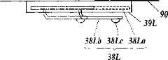
图5是行驶玩具100的主视图,图6及图7是悬架部件38L的主要部分俯视图。Fig. 5 is a front view of the runningtoy 100, and Figs. 6 and 7 are plan views of main parts of thesuspension member 38L.

悬架部件38L备有:基部38La,支承在悬架部件保持部39L上,呈长方形的板状;板簧部38Lb,从该基部38La沿Y轴方向以悬臂状态伸出,由弹性材料形成;突起部38Lc,设于板簧部38Lb的伸出前端部一侧,呈半球状。在所述悬架部件38L的突起部38Lc嵌合在设于对置板33Le上的圆形凹部33Lf中的状态下,悬架部件38L对车轮支承体33L赋予弹性力。Thesuspension member 38L is provided with: a base portion 38La supported on the suspensionmember holding portion 39L and having a rectangular plate shape; and a plate spring portion 38Lb protruding from the base portion 38La in a cantilever state in the Y-axis direction and formed of an elastic material; The protruding portion 38Lc is provided on the protruding front end side of the leaf spring portion 38Lb, and has a hemispherical shape. Thesuspension member 38L applies elastic force to thewheel support 33L in a state where the protrusion 38Lc of thesuspension member 38L is fitted into the circular recess 33Lf provided on the facing plate 33Le.

如图5所示,在各前轮22L、22R分别接地时,各前轮22L、22R分别在车体90的宽度方向(X轴方向)上位于比支承轴34L、34R更靠外侧的位置上,所以在行驶玩具100的自重作用下,车轮支承体33L、33R以支承轴34L、34R为中心向使其上部接近车体90的侧面的方向转动。As shown in FIG. 5 , when thefront wheels 22L, 22R are on the ground, thefront wheels 22L, 22R are located on the outer side of thesupport shafts 34L, 34R in the width direction (X-axis direction) of thevehicle body 90 . Therefore, the wheel supports 33L, 33R rotate around thesupport shafts 34L, 34R in a direction in which their upper parts approach the side surfaces of thevehicle body 90 under the weight of the runningtoy 100 .

由此,各前轮22L、22R及车轮支承体33L、33R从正面观察时相互呈八字状倾斜的状态,设于车轮支承体33L、33R的上侧的对置板33Le、33Re向接近车体90的侧面的方向移动。但是,由于在车体90的侧面上设有向远离该侧面的方向产生排斥力的悬架部件38L、38R,所以车轮支承体33L、33R经由对置板33Le、33Re而被悬架部件38L、38R的弹性力推开。由此,左右前轮22L、22R维持着相互呈八字状倾斜的状态,通过悬架部件38L、38R来缓和各前轮22L、22R从地面承受的震动,从而可以得到对车体90的缓冲效果。As a result, thefront wheels 22L, 22R and the wheel supports 33L, 33R are in the state of being inclined in a figure-eight shape when viewed from the front, and the facing plates 33Le, 33Re provided on the upper side of the wheel supports 33L, 33R approach the vehicle body. 90 to move in the direction of the side. However, since thesuspension members 38L, 38R that generate repulsive force in a direction away from the side surfaces are provided on the side surfaces of thevehicle body 90, the wheel supports 33L, 33R are supported by thesuspension members 38L, 33R via the opposing plates 33Le, 33Re. The elastic force of the 38R pushes away. As a result, the left and rightfront wheels 22L, 22R maintain the state of being inclined in a figure-of-eight shape, and the vibrations received by thefront wheels 22L, 22R from the ground are moderated by thesuspension members 38L, 38R, so that a cushioning effect on thevehicle body 90 can be obtained. .

而且,由于作为转向轮的前轮22L、22R维持着下侧变宽的倾斜状态,所以在没有作用外力的状态(没有通过转向机构60进行转向操作的状态)下,可以维持直线前进的转向状态。In addition, since thefront wheels 22L and 22R, which are steered wheels, maintain an inclined state in which the lower side widens, the steering state of straight forward movement can be maintained in a state where no external force is applied (a state where the steering operation is not performed by the steering mechanism 60 ). .

另外,如前所述,车轮支承体33L、33R可以相对于车体90在前后方向上进行位置调整。因此,对于悬架部件38L、38R,也必须能够相对于车体90在前后方向上进行位置调整。因此,如图5及图7所示,悬架保持部39L(39R也一样)支承着悬架部件38L的长条状的基部,使其能够沿Y轴方向滑动。由此,可以相对于在Y轴方向上进行了移动调节的车轮支承体33L的对置板33Le上设置的凹部33Lf,在Y轴方向上对悬架部件38L进行同样的移动调节,从而使其突起部38Lc嵌合在凹部33Lf中。因此,即使在进行了前轮22L、22R的前后位置调节的情况下,也可以维持一定的缓冲效果。In addition, as described above, the position of the wheel supports 33L, 33R can be adjusted in the front-rear direction with respect to thevehicle body 90 . Therefore, thesuspension members 38L, 38R must also be capable of position adjustment in the front-rear direction with respect to thevehicle body 90 . Therefore, as shown in FIGS. 5 and 7 , thesuspension holding portion 39L (39R is the same) supports the elongated base portion of thesuspension member 38L so as to be slidable in the Y-axis direction. Thus, thesuspension member 38L can be similarly adjusted for movement in the Y-axis direction with respect to the concave portion 33Lf provided on the opposing plate 33Le of thewheel support body 33L that has been adjusted for movement in the Y-axis direction, thereby making it The protrusion 38Lc is fitted into the recess 33Lf. Therefore, even when the front-back position adjustment of thefront wheels 22L, 22R is performed, a constant cushioning effect can be maintained.

如上所述,在各前轮支承机构30L、30R中,与设于车轮支承体33L、33R的上部上的对置板33Le、33Re对置地、在车体90的侧面侧配置有悬架部件38L、38R。因此,以Y轴方向为中心得到轴支承的前轮22L、22R及车轮支承体33L、33R在呈下侧变宽的八字状倾斜的状态下,由悬架部件38L、38R赋予了弹性的排斥力,从而可以相对于车体90缓冲根据路面状态产生的震动和冲击。As described above, in each of the frontwheel support mechanisms 30L, 30R, thesuspension member 38L is arranged on the side surface of thevehicle body 90 so as to face the opposing plates 33Le, 33Re provided on the upper portions of thewheel support bodies 33L, 33R. , 38R. Therefore, thefront wheels 22L, 22R and the wheel supports 33L, 33R pivotally supported around the Y-axis direction are provided with elastic repulsion by thesuspension members 38L, 38R in a state of being inclined in a figure-eight shape with the lower side widening. force, so that vibrations and shocks generated according to the state of the road surface can be buffered relative to thevehicle body 90 .

而且,在各前轮支承机构30L、30R中,通过支承轴34L、34R对车轮支承体33L、33R进行轴支承、并且使其可沿该支承轴34L、34R滑动,利用间隔件37L、37R来确定其位置,所以,与使车体整体伸缩的构成不同,可以仅通过轻微的局部构成的调整来进行轴距的调整。因此,可以实现进行调整的构成的简易化、调整作业的容易化以及迅速化。Furthermore, in each of the frontwheel support mechanisms 30L, 30R, the wheel supports 33L, 33R are pivotally supported by thesupport shafts 34L, 34R, and are slidable along thesupport shafts 34L, 34R. Since its position is determined, the wheelbase can be adjusted only by slightly adjusting the partial structure, unlike the structure that expands and contracts the entire vehicle body. Therefore, it is possible to simplify the configuration for adjustment, and to simplify and speed up the adjustment work.

进而,车轮支承体33L、33R是从车体分离地在前后方向上进行移动调节的构成,并且是主要对前轮22L、22R和转向旋转体32L、32R进行支承的部件,所以容易实现小型化,在进行该车轮支承体33L、33R的移动调节时,不必担心会如以往那样导致收纳在车体内的各种构成的配置和功能不能实现的问题,能够以简易的构成进行轴距的调节。Furthermore, the wheel supports 33L, 33R are separated from the vehicle body and are configured to move and adjust in the front-rear direction, and are components that mainly support thefront wheels 22L, 22R and thesteering rotors 32L, 32R, so miniaturization is easy. When adjusting the movement of the wheel supports 33L, 33R, there is no need to worry about the arrangement and function of various components housed in the vehicle body as in the past, and the adjustment of the wheel base can be performed with a simple structure.

而且,由于车轮支承体33L、33R容易实现小型化·轻量化,所以车体90和车轮支承体33L、33R不易产生因强度不足引起的应变,从而可以维持良好的行驶状态。Furthermore, since the wheel supports 33L, 33R can be easily reduced in size and weight, thevehicle body 90 and the wheel supports 33L, 33R are less prone to strain due to insufficient strength, and can maintain a good running state.

进而,由于转向机构60的转向臂69具有如备有长孔的环状部69Lc、69Rc那样、即使在转向旋转体32L、32R的前后位置发生了变化的情况下也能够在左右方向上传递动力的构造,所以可以进行不妨碍前轮22L、22R的前后位置调节的、稳定的转向。Furthermore, since thesteering arm 69 of thesteering mechanism 60 has the annular portions 69Lc, 69Rc with elongated holes, power can be transmitted in the left-right direction even when the front-rear positions of thesteering rotating bodies 32L, 32R change. Therefore, it is possible to perform stable steering without interfering with the front-rear position adjustment of thefront wheels 22L, 22R.

而且,由于悬架部件38L、38R是可进行前后位置调节地支承在悬架保持部39L、39R上,所以即使在车轮支承体33L、33R的前后位置发生了变化的情况下,也可以对车轮支承体33L、33R向远离车体90的方向赋予弹性力,从而不管前轮22L、22R是否进行了前后位置调节,都可以得到稳定的缓冲效果。Moreover, since thesuspension members 38L, 38R are supported on thesuspension holders 39L, 39R so that the front and rear positions can be adjusted, even if the front and rear positions of the wheel supports 33L, 33R change, the wheels can be adjusted. The supports 33L, 33R impart elastic force in a direction away from thevehicle body 90, so that a stable cushioning effect can be obtained regardless of whether thefront wheels 22L, 22R are adjusted in the front-rear position.

进而,即使进行前轮22L、22R的移动调整,悬架部件38L、38R也不必进行烦杂的重装作业,仅通过滑动操作即可容易地处理,从而可以实现作业的简易迅速化。Furthermore, even if the movement adjustment of thefront wheels 22L, 22R is performed, thesuspension members 38L, 38R can be easily handled only by sliding operation without complicated reinstallation work, so that the work can be simplified and speeded up.

(前轮支承机构的变形例)(Modification of front wheel support mechanism)

前述转向机构60构成为,在转向臂69上形成有齿条,通过由转向用直流马达13驱动旋转的小齿轮64使转向臂69在X轴方向上移动,但并不限于此,在必要时可以使用对转向臂69赋予移动力的任何方法。例如,可以是如螺线管或直动马达那样的采用了电磁铁和磁体或永久磁铁的构成,或在旋转式马达的输出轴的半径方向上装备臂、通过臂的转动来使转向臂69左右移动的构成。Theaforementioned steering mechanism 60 is configured such that a rack is formed on thesteering arm 69, and thesteering arm 69 is moved in the X-axis direction by thepinion gear 64 driven to rotate by thesteering DC motor 13. Any method of imparting a moving force to thesteering arm 69 may be used. For example, it may be a configuration using an electromagnet and a magnet or a permanent magnet such as a solenoid or a linear motor, or an arm is provided in the radial direction of the output shaft of a rotary motor, and thesteering arm 69 is turned by turning the arm. Composition moving left and right.

另外,转向臂69和转向旋转体32L、32R的卡合部位是通过具有长孔的环状部69Lc、69Rc与卡合突起32Lc、32Rc进行连结的,但只要允许在相互间产生相对的Y轴方向移动、并且X轴方向的移动是联动进行的,则可以是任何形式的构造。例如,可以将长孔和圆棒状的突起互相设置在相反侧,还可以采用槽来代替长孔。另外,也可以将沿主动臂或者从动臂的延伸方向移动的滑动部件设置在两个臂中的某一个上,并将另一个臂和该滑动部件以能够以Z轴方向为中心转动的方式连结起来。In addition, the engaging portions of thesteering arm 69 and thesteering rotating bodies 32L, 32R are connected to the engaging protrusions 32Lc, 32Rc through the annular portions 69Lc, 69Rc having elongated holes. direction movement, and the movement in the X-axis direction is carried out in conjunction, then any form of structure can be used. For example, the elongated hole and the round rod-shaped protrusion may be provided on opposite sides of each other, or a groove may be used instead of the elongated hole. In addition, a sliding member that moves along the extending direction of the master arm or the slave arm may be provided on one of the two arms, and the other arm and the sliding member may be rotatable around the Z-axis direction. link up.

另外,前轮支承机构30L、30R并不限于前述构成,只要是能够进行使前轮22L、22R转向所需的转动、并且能够在Y轴方向上进行移动调节,则可以是任何形式的构成。例如,可以将转动支承部35L、36L设置成可以相对于车体90在Y轴方向上移动、使车轮支承体33L能够与支承轴34L一起沿Y轴方向移动,也可以利用凸起部或者嵌合孔之类的凹凸构造来使转动支承部35L、36L能够相对于车体90进行装卸、并通过在车体侧面一侧沿Y轴方向设置多个凹部或者凸部来进行转动支承部35L、36L的位置调整。或者,可以采用下述构成:在车轮支承体33L上同轴地固定设置至少两个以上的C形环,在转动支承部35L、36L上设置直径比C形环的内径大的支承轴34L,在该支承轴34L的外周面上沿其长度方向设置用以可旋转地安装C形环的多个圆周槽。这种情况下,通过选择多个圆周槽并利用C形环安装车轮支承体33,可以在Y轴方向上对该车轮支承体33进行位置调整。In addition, the frontwheel support mechanisms 30L, 30R are not limited to the aforementioned configurations, and may have any configuration as long as they are capable of turning required to steer thefront wheels 22L, 22R and capable of moving and adjusting in the Y-axis direction. For example, therotation support parts 35L, 36L may be provided so as to be movable in the Y-axis direction relative to thevehicle body 90, so that thewheel support body 33L can move in the Y-axis direction together with thesupport shaft 34L, or it may be possible to use a boss or an insert to move in the Y-axis direction. Concavo-convex structures such as holes are used to enable therotating support parts 35L, 36L to be attached and detached relative to thevehicle body 90, and a plurality of concave or convex parts are provided on the side of the vehicle body along the Y-axis direction to perform therotating support parts 35L, 36L, 36L position adjustment. Alternatively, the following configuration can be adopted: at least two or more C-shaped rings are coaxially fixed on thewheel support body 33L, and asupport shaft 34L having a diameter larger than the inner diameter of the C-shaped ring is provided on therotation support parts 35L and 36L. A plurality of circumferential grooves for rotatably mounting a C-ring are provided on the outer peripheral surface of thesupport shaft 34L along its length direction. In this case, by selecting a plurality of circumferential grooves and mounting the wheel support 33 with a C-ring, the position of the wheel support 33 can be adjusted in the Y-axis direction.

前轮支承机构30R也是同样的。The same applies to the frontwheel support mechanism 30R.

另外,能够通过悬架保持部39L、39R而在Y轴方向上对前轮支承机构30L、30R的悬架部件38L、38R进行移动调节,但即使对前轮22L、22R的前后方向位置进行调节、则不管其位置变化如何,只要是对前轮22L、22R赋予弹性的缓冲效果,则可以是任何形式的构成。In addition, thesuspension members 38L, 38R of the frontwheel support mechanisms 30L, 30R can be moved and adjusted in the Y-axis direction by thesuspension holding parts 39L, 39R, but even if the front-rear direction positions of thefront wheels 22L, 22R are adjusted , regardless of the change in its position, as long as it imparts an elastic cushioning effect to thefront wheels 22L, 22R, any configuration may be used.

例如,也可以将悬架部件作成沿Y轴方向固定装备在车体90上的长条状弹性体。For example, the suspension member may be formed as an elongated elastic body fixedly mounted on thevehicle body 90 along the Y-axis direction.

或者,也可以在车体90上沿Y轴方向排列地固定装备多个悬架部件。Alternatively, a plurality of suspension members may be fixedly mounted on thevehicle body 90 along the Y-axis direction.

或者,也可以在各车轮支承体33L、33R的对置板33Le、33Re上设置与车体90的侧面抵接的、由弹性体构成的悬架部件。Alternatively, a suspension member made of an elastic body that contacts the side surface of thevehicle body 90 may be provided on the opposing plates 33Le, 33Re of the wheel supports 33L, 33R.

在这些情况下,进行了前轮22L、22R的前后位置调节之后,不必进行悬架部件的位置调节作业,车轮支承体33L、33R即可由悬架部件赋予弹性力,维持相对于前轮22L、22R的缓冲效果。而且,在这些情况下,可以不设置悬架保持部39L、39R。In these cases, after the front-rear position adjustment of thefront wheels 22L, 22R is performed, the wheel supports 33L, 33R can be given elastic force by the suspension members without performing the position adjustment work of the suspension members, and maintain relative to thefront wheels 22L, 22R. 22R cushioning effect. Also, in these cases, thesuspension holding portions 39L, 39R may not be provided.

(转向机构)(steering mechanism)

在车体90的前部备有马达及机构收纳部61,在该马达及机构收纳部61的内部设有马达·机构收纳室。并且,在马达·机构收纳室中设置有转向用直流马达13。另外,在车体90上,装卸自如地安装有将马达·机构收纳室的上侧封闭起来的盖体。又,为了将马达收纳室和机构收纳室区分开、从上侧将马达收纳室和机构收纳室分别封闭起来,也可以分别设置单独的盖体。A motor andmechanism storage unit 61 is provided at the front portion of thevehicle body 90 , and a motor and mechanism storage room is provided inside the motor andmechanism storage unit 61 . In addition, aDC motor 13 for steering is installed in the motor/mechanism storage room. In addition, a cover body that closes the upper side of the motor/mechanism storage chamber is detachably attached to thevehicle body 90 . In addition, in order to separate the motor storage room and the mechanism storage room and to seal the motor storage room and the mechanism storage room from the upper side, separate covers may be provided.

作为转向用直流马达13,使用可正转·反转(正反转)的马达。转向用直流马达13以轴13a从马达壳向车体90的后方突出的方式设置在马达·机构收纳室中。如图8A、图8B所示,在轴13a上,经由离合器机构63设有齿轮(小齿轮)64。离合器机构63包括:圆板(保持板)63a、离合器片63b及外筒63c。即,在轴13a上固定着圆板63a。该圆板63a尽管没有特别限定,但在这里构成为圆板状。在该圆板63a的端面上,设置有多个离合器片63b。各离合器片63b沿轴13a的半径方向动作自如地安装在圆板63a上。即,在圆板63a上,形成有从其旋转中心大致放射状地延伸的导向件63d,各离合器片63b沿该导向件63a在轴13a的半径方向上动作自如。各离合器片63d的至少外端侧构成为棒状。并且,在圆板63a旋转时,由于作用在各离合器片63d上的离心力的作用,各离合器片63d向轴13a的半径方向上的外侧动作。As theDC motor 13 for steering, a motor capable of forward rotation and reverse rotation (forward and reverse rotation) is used. Thesteering DC motor 13 is installed in the motor/mechanism storage room such that ashaft 13a protrudes from the motor case toward the rear of thevehicle body 90 . As shown in FIGS. 8A and 8B , a gear (pinion) 64 is provided on theshaft 13 a via aclutch mechanism 63 . Theclutch mechanism 63 includes a circular plate (holding plate) 63a, aclutch plate 63b, and anouter cylinder 63c. That is, thedisc 63a is fixed to theshaft 13a. Thedisk 63a is not particularly limited, but is configured in a disk shape here. A plurality ofclutch discs 63b are provided on the end face of thecircular plate 63a. Eachclutch plate 63b is attached to thecircular plate 63a freely movable along the radial direction of theshaft 13a. That is, aguide 63d extending substantially radially from the center of rotation is formed on thecircular plate 63a, and eachclutch disc 63b is movable in the radial direction of theshaft 13a along theguide 63a. At least the outer end side of eachclutch plate 63d is formed in a rod shape. Then, when thedisc 63a rotates, eachclutch plate 63d moves outward in the radial direction of theshaft 13a due to the centrifugal force acting on eachclutch plate 63d.

另一方面,外筒63c具有从轴13a的半径方向上的外侧将圆板63a及离合器片63d围绕起来的周壁。这样,圆板63a在转向用直流马达13的动力作用下旋转时,由于作用在各离合器片63d上的离心力的作用,各离合器片63d向轴13a的半径方向上的外侧动作,各离合器片63d压接在外筒63c的周壁内表面上,圆板63a和外筒63c一体地旋转。而在圆板63a不旋转时,外筒63c相对于圆板63a空转自如。On the other hand, theouter cylinder 63c has a peripheral wall that surrounds thedisk 63a and theclutch plate 63d from the outside in the radial direction of theshaft 13a. In this way, when thecircular plate 63a rotates under the power of thesteering DC motor 13, due to the centrifugal force acting on eachclutch plate 63d, eachclutch plate 63d moves outward in the radial direction of theshaft 13a, and eachclutch plate 63d Thecircular plate 63a and theouter cylinder 63c rotate integrally by being crimped on the inner surface of the peripheral wall of theouter cylinder 63c. On the other hand, when thecircular plate 63a is not rotating, theouter cylinder 63c can freely rotate idly with respect to thecircular plate 63a.

齿轮64与形成于转向臂69上的齿条69d啮合。结果,齿轮64在转向用直流马达13的动力的作用下正向或反向旋转时,转向臂69与该旋转方向相应地左右动作。Thegear 64 meshes with arack 69d formed on thesteering arm 69 . As a result, when thegear 64 rotates forward or reverse by the power of thesteering DC motor 13 , thesteering arm 69 moves left and right according to the rotation direction.

又,在本实施方式中,是通过转向用直流马达13、经由齿轮机构使转向臂69动作的,但也可以构成为利用电磁铁使转向臂69左右动作。即,将永久磁铁或者线圈中的一个设置在转向臂69上,另一方面,在车体90的固定部分上设置永久磁铁或者线圈中的另一个,通过进行线圈的通电控制,使转向臂69左右动作。In addition, in this embodiment, thesteering arm 69 is moved by thesteering DC motor 13 via a gear mechanism, but it may be configured to move thesteering arm 69 left and right by an electromagnet. That is, one of the permanent magnet or the coil is arranged on thesteering arm 69, and on the other hand, the other of the permanent magnet or the coil is arranged on the fixed part of thevehicle body 90, and thesteering arm 69 is turned by controlling the energization of the coil. Move left and right.

(行驶用直流马达)(DC motor for driving)

在车体90的后部备有马达及机构收纳部71,该马达及机构收纳部71的内部如图9所示,区分成马达收纳室71a和机构收纳室71b。在马达收纳室71a中设置有行驶用直流马达4。A motor andmechanism storage unit 71 is provided at the rear of thevehicle body 90, and the inside of the motor andmechanism storage unit 71 is divided into a motor storage room 71a and a mechanism storage room 71b as shown in FIG. 9 . TheDC motor 4 for running is installed in the motor storage room 71a.

作为行驶用直流马达4,使用的是可正转·反转(正反转)的马达。行驶用直流马达4以轴4a从马达壳4b向车体90的宽度方向突出的方式设置在马达收纳室71a中。在轴4a上设有齿轮(小齿轮)81a。齿轮81a设置在下述位置上:在将行驶用直流马达4的主体设置在马达收纳室71a中时,齿轮81a面向机构收纳室71b。在行驶用直流马达4的马达壳4b的外周面上设有2个端子4c、4d。As theDC motor 4 for traveling, a motor capable of forward rotation and reverse rotation (forward and reverse rotation) is used. The runningDC motor 4 is provided in the motor storage chamber 71 a such that the shaft 4 a protrudes from the motor case 4 b in the width direction of thevehicle body 90 . A gear (pinion) 81a is provided on the shaft 4a. Thegear 81a is provided at a position where thegear 81a faces the mechanism storage chamber 71b when the main body of the travelingDC motor 4 is installed in the motor storage chamber 71a. Two terminals 4c and 4d are provided on the outer peripheral surface of the motor housing 4b of the runningDC motor 4 .

另一方面,马达收纳室71a的底板由印刷电路布线板74构成。在印刷电路布线板74的表面上,在与前述端子4c、4d对应的部位上形成有电极图形74a、74b。电极图形74a、74b通过印刷或蒸镀等形成于印刷电路布线板74上。On the other hand, the bottom plate of the motor housing chamber 71 a is constituted by a printed wiring board 74 . On the surface of the printed wiring board 74, electrode patterns 74a, 74b are formed at portions corresponding to the aforementioned terminals 4c, 4d. The electrode patterns 74a, 74b are formed on the printed wiring board 74 by printing, vapor deposition, or the like.

另外,在将行驶用直流马达4载置于印刷电路布线板74上时,端子4c、4d与电极图形74a、74b电气地连接,从而可以对行驶用直流马达4供电。Also, when the runningDC motor 4 is mounted on the printed wiring board 74, the terminals 4c, 4d are electrically connected to the electrode patterns 74a, 74b, so that the runningDC motor 4 can be powered.

又,印刷电路布线板74既可以是平板状,也可以是以上侧凹陷的方式弯曲。总之,只要形成为与马达壳4b相对应的形状、并能使端子4c、4d与电极图形74a、74b可靠地抵接即可。In addition, the printed wiring board 74 may be flat or bent so that the upper side thereof is concave. In short, it only needs to be formed in a shape corresponding to the motor case 4b so that the terminals 4c, 4d can be reliably brought into contact with the electrode patterns 74a, 74b.

根据具有以上构造的行驶玩具100,由于使用了形成有电极图形74a、74b的印刷电路布线板74,所以行驶玩具100的组装变得极为容易。即,在不使用印刷电路布线板74的情况下,在将电极板(导电板)一片一片地组装或电气地连接到车体侧时,需要进行导线的钎焊等精细的作业,而与之相对,在使用形成有电极图形74a、74b的印刷电路布线板74的情况下,在组装时只需将印刷电路布线板74组装到车体上即可,所以行驶玩具100的组装变得极为容易。According to the runningtoy 100 having the above structure, since the printed wiring board 74 on which the electrode patterns 74a, 74b are formed is used, the assembly of the runningtoy 100 becomes extremely easy. That is, in the case where the printed circuit wiring board 74 is not used, when the electrode plates (conductive plates) are assembled one by one or electrically connected to the vehicle body side, delicate work such as soldering of wires is required. In contrast, in the case of using the printed wiring board 74 formed with the electrode patterns 74a, 74b, only the printed wiring board 74 needs to be assembled on the vehicle body at the time of assembly, so the assembly of the travelingtoy 100 becomes extremely easy. .

另外,在使用导线的情况下,在进行电气连接时,有弄错布线的危险,但使用形成有电极图形74a、74b的印刷电路布线板74的情况下,通过端子抵接在电极图形74a、74b上即可实现电气的连接,没有上述问题。In addition, in the case of using lead wires, there is a risk of wiring errors during electrical connection, but in the case of using the printed circuit board 74 formed with electrode patterns 74a, 74b, the electrode patterns 74a, 74b are contacted by terminals. The electrical connection can be realized on the 74b, without the above-mentioned problems.

(行驶机构)(travel mechanism)

在机构收纳室71b中,设置有用于将行驶用直流马达4的行驶转矩向各后轮21L、21R传递的行驶机构80。行驶机构80由包括前述齿轮81a在内的齿轮机构81构成。The travelingmechanism 80 for transmitting the traveling torque of the travelingDC motor 4 to the respectiverear wheels 21L and 21R is provided in the mechanism housing chamber 71b. The travelingmechanism 80 is constituted by a gear mechanism 81 including theaforementioned gear 81a.

即,在机构收纳室71b中,延伸有与轴4a平行的轴82。如图10所示,在轴82上相对于轴82空转自如地设有齿轮81b。齿轮81b构成为沿轴82的轴线方向移动自如。另外,在该齿轮81b的左右位置上一体地设有齿轮81Lc、81Rc。That is, in the mechanism housing chamber 71b, theshaft 82 parallel to the shaft 4a extends. As shown in FIG. 10 , agear 81b is provided on theshaft 82 so as to be idly rotatable with respect to theshaft 82 . Thegear 81b is configured to be movable in the axial direction of theshaft 82 . In addition, gears 81Lc and 81Rc are integrally provided at the left and right positions of thegear 81b.

而且,在机构收纳室71b中延伸有与轴82平行的轴(后轮车轴)83。在轴83上固定地设有齿轮81Ld、81Rd。在齿轮81b沿轴82的轴线方向移动时,与其移动方向对应地、齿轮81Lc、81Rc择一地与该齿轮81Ld、81Rd啮合。具体地说,当齿轮81b向轴82的轴向左侧移动时,齿轮81Lc与齿轮81Ld啮合,当齿轮81b向轴82的轴向右侧移动时,齿轮81Rc与齿轮81Rd啮合。通过改变齿轮的啮合状态,可以变化行驶转矩。Furthermore, a shaft (rear wheel axle) 83 parallel to theshaft 82 extends in the mechanism housing chamber 71b. Gears 81Ld and 81Rd are fixedly provided on theshaft 83 . When thegear 81b moves in the axial direction of theshaft 82, the gears 81Lc and 81Rc alternately mesh with the gears 81Ld and 81Rd corresponding to the moving direction. Specifically, when thegear 81b moves to the axial left of theshaft 82, the gear 81Lc meshes with the gear 81Ld, and when thegear 81b moves to the axial right of theshaft 82, the gear 81Rc meshes with the gear 81Rd. By changing the meshing state of the gears, the driving torque can be varied.

又,为了使齿轮81b在轴82的轴线方向上移动,在车体90的下侧设有未图示的操作旋钮,通过该操作旋钮的操作使杆84左右移动,位于该杆84的两个爪84a、84b之间的齿轮81b被向左右推压,从而改变齿轮的啮合状态。Also, in order to move thegear 81b in the axial direction of theshaft 82, an operation knob (not shown) is provided on the lower side of thevehicle body 90, and the operation of the operation knob causes thelever 84 to move left and right. Thegear 81b between theclaws 84a, 84b is pushed left and right, thereby changing the meshing state of the gears.

(盖体)(cover body)

如图9所示,在车体90上,装卸自如地安装有将马达收纳室71a及机构收纳室71b的上侧封闭起来的盖体91。该盖体91发挥马达按压部件的作用。又,为了从上侧将马达收纳室71a和机构收纳室71b分别封闭起来,也可以分别设置单独的盖体。As shown in FIG. 9 , a cover body 91 is detachably attached to thevehicle body 90 for closing the upper sides of the motor storage chamber 71 a and the mechanism storage chamber 71 b. The cover body 91 functions as a motor pressing member. In addition, in order to close the motor storage chamber 71a and the mechanism storage chamber 71b from the upper side, separate lids may be provided respectively.

在盖体91上设有多个散热用开91a。而且,在盖体91上设有用于安装散热板92的狭缝93。构成为可以从狭缝93对散热板92进行装卸。作为散热板92,优选地采用金属、例如铜或铝等,但如果选择散热效果较好的形状,也可以采用合成树脂(例如ABS树脂)。The lid body 91 is provided with a plurality of openings 91 a for heat dissipation. Furthermore, a slit 93 for attaching the radiator plate 92 is provided on the cover body 91 . The radiator plate 92 is configured to be attachable and detachable through the slit 93 . Metal such as copper or aluminum is preferably used as the heat sink 92, but synthetic resin (such as ABS resin) may also be used if a shape with a better heat dissipation effect is selected.

根据具有以上构造的行驶玩具100,可以简单地更换散热板92,并可以由此来简单地改变散热性能。而且,可以根据行驶道路的状况而使用不同重量的散热板92。进而,还可以根据心情使用颜色和形状不同的散热板92。为了有效地发挥这些效果,优选地,准备散热性、重量、颜色、形状的任一项不同的多块散热板,从中选择符合要求的散热板使用。According to the runningtoy 100 having the above configuration, the heat dissipation plate 92 can be easily replaced, and thus the heat dissipation performance can be easily changed. Also, it is possible to use radiator plates 92 of different weights depending on the condition of the traveling road. Furthermore, you may use the heat sink 92 which differs in color and shape according to a mood. In order to effectively exert these effects, it is preferable to prepare a plurality of heat dissipation plates different in any one of heat dissipation, weight, color, and shape, and to select and use a heat dissipation plate that meets the requirements.

又,一次安装的散热板92的数量不仅限于一块。也可以将盖体91作成为能够安装两块以上的散热板92的形式。Also, the number of cooling plates 92 to be mounted at one time is not limited to one. The cover body 91 may be configured to allow attachment of two or more heat sinks 92 .

(驱动电路及控制电路)(drive circuit and control circuit)

行驶玩具构成为,搭载有行驶用直流马达以及转向用直流马达,利用来自遥控器的电波来对各直流马达的旋转方向进行远程控制。The driving toy is configured to include a running DC motor and a steering DC motor, and the rotation direction of each DC motor is remotely controlled by radio waves from a remote controller.

如图11所示,在行驶玩具内,内置有:接收电路1、控制IC2、驱动行驶用直流马达4的行驶马达驱动电路3、驱动转向用直流马达13的转向马达驱动电路8。As shown in FIG. 11 , in the traveling toy, there are built in: a receivingcircuit 1 , acontrol IC 2 , a travelingmotor driving circuit 3 for driving a travelingDC motor 4 , and a steeringmotor driving circuit 8 for driving asteering DC motor 13 .

从未图示的遥控操作装置发送的操作信号电波经由天线ANT而被接收电路1接收/解调,并输入到控制IC2。控制IC2将与输入的操作信号相对应的控制命令信号输送到行驶系统以及/或者转向系统的控制驱动电路。Operation signal radio waves transmitted from a remote control device not shown in the figure are received and demodulated by the receivingcircuit 1 via the antenna ANT, and input to thecontrol IC 2 . Thecontrol IC 2 sends a control command signal corresponding to the input operation signal to the control driving circuit of the traveling system and/or the steering system.

例如,在操作信号为前进命令时,控制IC2将前进命令信号SF输出到马达驱动电路3。行驶马达驱动电路3对直流马达4供给极性与前进方向相对应的电压。同样地,当操作信号为后退命令时,控制IC2将后退命令信号SB输出到行驶马达驱动电路3。行驶马达驱动电路3对直流马达4供给极性与后退方向相对应的电压。For example, when the operation signal is a forward command, thecontrol IC 2 outputs the forward command signal SF to themotor drive circuit 3 . The travelmotor drive circuit 3 supplies aDC motor 4 with a voltage having a polarity corresponding to the forward direction. Likewise, when the operation signal is a reverse command, thecontrol IC 2 outputs a reverse command signal SB to the travelmotor drive circuit 3 . The travelmotor drive circuit 3 supplies aDC motor 4 with a voltage having a polarity corresponding to the reverse direction.

另一方面,当操作信号为转向控制信号且为右转弯命令时,控制IC2将右转弯命令信号SR输出到转向马达驱动电路8。转向马达驱动电路8对直流马达13供给极性与右转弯方向对应的电压。同样地,当操作信号为左转弯命令时,控制IC2将左转弯命令信号SL输出到转向马达驱动电路8。转向马达驱动电路8对直流马达13供给极性与左转弯方向对应的电压。On the other hand, when the operation signal is a steering control signal and is a right turn command, thecontrol IC 2 outputs a right turn command signal SR to the steeringmotor drive circuit 8 . The steeringmotor drive circuit 8 supplies aDC motor 13 with a voltage having a polarity corresponding to the right turning direction. Likewise, when the operation signal is a left turn command, thecontrol IC 2 outputs a left turn command signal SL to the steeringmotor drive circuit 8 . The steeringmotor drive circuit 8 supplies aDC motor 13 with a voltage having a polarity corresponding to the left turning direction.

转向马达驱动电路8具有能够串联连接至少两个电池9、10的正极电源端子14以及负极电源端子15。The steeringmotor drive circuit 8 has a positivepower supply terminal 14 and a negativepower supply terminal 15 to which at least twobatteries 9 and 10 can be connected in series.

在供给电源电压Vcc的正极电源端子14和连接在GND电位上的负极电源端子15之间,串联连接有根据来自控制IC2的左转弯命令信号SL、右转弯命令信号SR而交替地导通(ON)或非导通(OFF)的PNP型晶体管(第1开关元件)Q5及NPN型晶体管(第2开关元件)Q6。Between the positivepower supply terminal 14 that supplies the power supply voltage Vcc and the negativepower supply terminal 15 connected to the GND potential, there are connected in series according to the left turn command signal SL and the right turn command signal SR from the control IC2, which are alternately conducted (ON). ) or non-conductive (OFF) PNP transistor (first switching element) Q5 and NPN transistor (second switching element) Q6.

在电池9、10之间的连接中点16、与晶体管Q5和晶体管Q6的连接中点17之间,连接有转向用直流马达13。ADC motor 13 for steering is connected between aconnection midpoint 16 between thebatteries 9 and 10 and aconnection midpoint 17 between the transistor Q5 and the transistor Q6.

在转向用直流马达13的旋转轴上,连结有与转向轮(前轮)相连的转向机构60。通过切换转向用直流马达13的旋转方向,可以经由该转向机构60来改变转向轮的朝向。Asteering mechanism 60 connected to steered wheels (front wheels) is coupled to the rotation shaft of thesteering DC motor 13 . By switching the rotation direction of thesteering DC motor 13 , the orientation of the steering wheels can be changed via thesteering mechanism 60 .

如图12所示,在电池9、10之间的连接中点16处设有自保持型的电源开关18,所述电源开关18在闭合时将转向用直流马达13的一侧的连接端子、与电池9的负极侧的端子16A和电池10的正极侧的端子16B电气地连接起来。As shown in Figure 12, a self-holdingtype power switch 18 is provided at theconnection midpoint 16 between thebatteries 9, 10. It is electrically connected to terminal 16A on the negative electrode side ofbattery 9 and terminal 16B on the positive electrode side ofbattery 10 .

通过闭合该电源开关18,电池9的负极侧和电池10的正极侧电气地连接,而且,转向用直流马达13的一侧的端子与电源开关18连接,所以串联连接的两个电池的电源电压Vcc(例如1.5V×2=3V)供给到各电路1、2、3、8,而且形成转向用直流马达13的电枢的电流路径。By closing thepower switch 18, the negative side of thebattery 9 is electrically connected to the positive side of thebattery 10, and the terminal on one side of thesteering DC motor 13 is connected to thepower switch 18, so the power supply voltage of the two batteries connected in series Vcc (for example, 1.5V×2=3V) is supplied to thecircuits 1 , 2 , 3 , and 8 and forms a current path for the armature of thesteering DC motor 13 .

又,在转向马达驱动电路8的两端加有电源电压Vcc(例如3V),但根据转向用直流马达13的各旋转方向而加在转向用直流马达13上的电压为电源电压Vcc的1/2(1.5V)。这是因为在后述的回路L1与回路L2的单位中使用的电池不同的缘故。Also, the power supply voltage Vcc (for example, 3V) is applied to both ends of the steeringmotor drive circuit 8, but the voltage applied to thesteering DC motor 13 according to the respective rotation directions of thesteering DC motor 13 is 1/1 of the power supply voltage Vcc. 2 (1.5V). This is because the batteries used in the units of the circuit L1 and the circuit L2 described later are different.

(电路动作)(circuit operation)

首先,将电源开关18(图12)闭合时,电池9和10经由负极侧的端子16A和正极侧的端子16B串联连接,而且转向用直流马达13与电池9和10的连接中点16(图11)连接。此时,在转向马达驱动电路8中形成两个闭合回路。First, when the power switch 18 ( FIG. 12 ) is closed, thebatteries 9 and 10 are connected in series via the terminal 16A on the negative side and the terminal 16B on the positive side, and theconnection midpoint 16 between theDC motor 13 for steering and thebatteries 9 and 10 ( FIG. 11) Connect. At this time, two closed loops are formed in the steeringmotor drive circuit 8 .

如图11所示,一个是回路L1:电池9→正极电源端子14→晶体管Q 5→连接中点17→转向用直流马达13→连接中点16→电池9。As shown in Figure 11, one is the circuit L1:battery 9→positivepower supply terminal 14→transistor Q5→connect tomidpoint 17→directcurrent motor 13 for steering→connect tomidpoint 16→battery 9.

另一个是回路L2:电池10→连接中点16→转向用直流马达13→连接中点17→晶体管Q 6→负极电源端子15→电池10。The other is loop L2:battery 10→connectmidpoint 16→directcurrent motor 13 for steering→connect midpoint 17→transistor Q6→negativepower supply terminal 15→battery 10.

现在,如果从控制IC2发出左转弯命令信号SL(电位L),则晶体管Q5为ON状态,电流沿回路L1的路径流动,转向用直流马达13与该电流方向对应地旋转而进行左转弯。另一方面,如果从控制IC2发出右转弯命令信号SR(电位H),则晶体管Q6为ON状态,电流沿与回路L1的情况反向的回路L 2的路径流动,转向用直流马达13与该电流方向对应地旋转而进行右转弯。Now, when the left turn command signal SL (potential L) is issued from the control IC2, the transistor Q5 is turned ON, the current flows along the path of the loop L1, and thesteering DC motor 13 rotates according to the direction of the current to turn left. On the other hand, when the right turn command signal SR (potential H) is issued from thecontrol IC 2, the transistor Q6 is turned ON, and the current flows along the path of the loop L2 reverse to that of the loop L1, and theDC motor 13 for steering is connected to the loop L2. The direction of the current is correspondingly rotated to make a right turn.

这样,晶体管Q 5和晶体管Q6交替地ON/OFF动作,即以所谓的相辅方式动作。伴随着这种ON/OFF动作,流过转向用直流马达13的电枢电流的朝向颠倒,从而可以对行驶玩具的行进方向进行控制。In this way, the transistor Q5 and the transistor Q6 operate alternately ON/OFF, that is, operate in a so-called complementary manner. Accompanying this ON/OFF operation, the direction of the armature current flowing through thesteering DC motor 13 is reversed, so that the traveling direction of the traveling toy can be controlled.

又,在使多个行驶玩具100同时行驶的情况下,要在行驶玩具100之间改变动作频率,在该情况下,出厂时需要选择与行驶玩具侧的动作频率一致的遥控器。因此,为了使得行驶玩具100和与其对应的遥控器的组合易于选择,优选地,按照动作频率改变天线用导线的颜色。Also, when driving a plurality of runningtoys 100 at the same time, the operating frequency needs to be changed among the runningtoys 100 . Therefore, in order to make it easy to select a combination of the travelingtoy 100 and the corresponding remote controller, it is preferable to change the color of the lead wire for antenna according to the operating frequency.

Claims (4)

Translated fromChinese
1.一种行驶玩具,其特征是,备有将马达收纳室封闭起来的盖体,所述马达收纳室用于收纳行驶用直流马达,在前述盖体上以可装卸的方式安装有将由前述行驶用直流马达产生的热量发散出去的散热板。1. A driving toy, characterized in that it is equipped with a cover that closes a motor storage room, the motor storage room is used to accommodate a DC motor for driving, and the cover is detachably mounted with a A radiator plate that dissipates heat generated by a DC motor for driving.2.如权利要求1所述的行驶玩具,其特征在于,前述盖体可装卸地设置在主体上,前述马达收纳室中收纳的前述行驶用直流马达以可更换的方式构成。2. The driving toy according to claim 1, wherein the cover is detachably mounted on the main body, and the driving DC motor accommodated in the motor storage chamber is configured to be replaceable.3.如权利要求1所述的行驶玩具,其特征在于,前述盖体设置成可对前述马达收纳室进行开闭,前述马达收纳室中收纳的前述行驶用直流马达以可更换的方式构成。3 . The driving toy according to claim 1 , wherein the cover body is configured to open and close the motor storage chamber, and the driving DC motor housed in the motor storage chamber is replaceable. 4 .4.如权利要求1-3的任一项所述的行驶玩具,其特征在于,在前述盖体上设有散热用开口。4. The traveling toy according to any one of claims 1-3, wherein an opening for heat dissipation is provided on the lid.
CN 2005200030972004-10-132005-03-17Running toyExpired - LifetimeCN2841109Y (en)

Applications Claiming Priority (2)

Application NumberPriority DateFiling DateTitle
JP2004299068AJP3724585B1 (en)2004-10-132004-10-13 Traveling toy
JP299068/042004-10-13

Publications (1)

Publication NumberPublication Date
CN2841109Ytrue CN2841109Y (en)2006-11-29

Family

ID=34880145

Family Applications (2)

Application NumberTitlePriority DateFiling Date
CN 200520003097Expired - LifetimeCN2841109Y (en)2004-10-132005-03-17Running toy
CNB2005100551433AExpired - Fee RelatedCN100409914C (en)2004-10-132005-03-17 driving toy

Family Applications After (1)

Application NumberTitlePriority DateFiling Date
CNB2005100551433AExpired - Fee RelatedCN100409914C (en)2004-10-132005-03-17 driving toy

Country Status (3)

CountryLink
JP (1)JP3724585B1 (en)
CN (2)CN2841109Y (en)
HK (1)HK1072158A2 (en)

Cited By (1)

* Cited by examiner, † Cited by third party
Publication numberPriority datePublication dateAssigneeTitle
CN100409914C (en)*2004-10-132008-08-13株式会社多美 driving toy

Family Cites Families (14)

* Cited by examiner, † Cited by third party
Publication numberPriority datePublication dateAssigneeTitle
JPH0475597U (en)*1990-11-151992-07-01
JP3007182U (en)*1994-07-261995-02-07株式会社大和科学教材研究所 Motor unit
CN2228794Y (en)*1995-07-081996-06-12李宽庆Variable-speed cross-country type controlled electric toy car
JP3523954B2 (en)*1996-01-302004-04-26株式会社リコー Thermal fixing device
US5683284A (en)*1996-02-121997-11-04Hart Enterprises, Inc.Gyroscopic top toy
JP3041179U (en)*1997-02-071997-09-09株式会社セガ・ヨネザワ Motor driven toys
JP2000336797A (en)*1999-05-282000-12-05Misawa Homes Co LtdHeat-insulating board for small kitchen range
JP2002166064A (en)*2000-12-052002-06-11Tomy Co Ltd Suspension for traveling toys and traveling toys
JP3724636B2 (en)*2000-11-062005-12-07株式会社トミー Motor structure for toy and car toy for racing
JP2003078270A (en)*2001-09-072003-03-14Hitachi Ltd Electronic equipment
JP3834536B2 (en)*2002-08-282006-10-18京商株式会社 Radio control car toy
JP2004217377A (en)*2003-01-162004-08-05Kyocera Mita CorpPaper feeding mechanism and image forming device mounted with the same
CN2607182Y (en)*2003-03-062004-03-24许福林Four-weel driven toy automobile with detachable electric remote-controller
JP3724585B1 (en)*2004-10-132005-12-07株式会社トミー Traveling toy

Cited By (1)

* Cited by examiner, † Cited by third party
Publication numberPriority datePublication dateAssigneeTitle
CN100409914C (en)*2004-10-132008-08-13株式会社多美 driving toy

Also Published As

Publication numberPublication date
CN100409914C (en)2008-08-13
HK1072158A2 (en)2005-08-12
CN1759911A (en)2006-04-19
JP3724585B1 (en)2005-12-07
JP2006109992A (en)2006-04-27

Similar Documents

PublicationPublication DateTitle
US7291951B2 (en)Actuator including intermediate wall
CN2841108Y (en)Running toy
CN101034239A (en)Lens protecting apparatus for cellular phone camera
CN1882230A (en)Electronic apparatus
CN2825039Y (en)Driving toy
CN2841110Y (en)Running toy
CN2841109Y (en)Running toy
CN2817939Y (en)Motor-driven circuit and driving toy
CN2827483Y (en)Toy vehicle
WO2016151414A1 (en)Illumination devices
HK1090865A (en)A running toy
JP3740162B1 (en) Traveling toy
JP3724636B2 (en) Motor structure for toy and car toy for racing
HK1090866A (en)A running toy
JP2009102013A (en)Actuator
JP5188930B2 (en) Electric motor
CN206344144U (en)Waist structure and anthropomorphic robot
HK1090867B (en)A running toy
CN1956864A (en) Mirror adjustment actuator and manufacturing method thereof
JP4777766B2 (en) motor
JP2003136463A (en)Movable part structure of robot
JP2004187428A (en)Motor

Legal Events

DateCodeTitleDescription
C14Grant of patent or utility model
GR01Patent grant
AV01Patent right actively abandoned

Effective date of abandoning:20080813

C25Abandonment of patent right or utility model to avoid double patenting

[8]ページ先頭

©2009-2025 Movatter.jp