CN2809969Y - connector assembly - Google Patents
connector assemblyDownload PDFInfo
- Publication number
- CN2809969Y CN2809969YCNU200520072489XUCN200520072489UCN2809969YCN 2809969 YCN2809969 YCN 2809969YCN U200520072489X UCNU200520072489X UCN U200520072489XUCN 200520072489 UCN200520072489 UCN 200520072489UCN 2809969 YCN2809969 YCN 2809969Y
- Authority
- CN
- China
- Prior art keywords
- connector
- audio
- earphone
- terminals
- conductive
- Prior art date
- Legal status (The legal status is an assumption and is not a legal conclusion. Google has not performed a legal analysis and makes no representation as to the accuracy of the status listed.)
- Expired - Fee Related
Links
Images


Classifications
- H—ELECTRICITY
- H04—ELECTRIC COMMUNICATION TECHNIQUE
- H04R—LOUDSPEAKERS, MICROPHONES, GRAMOPHONE PICK-UPS OR LIKE ACOUSTIC ELECTROMECHANICAL TRANSDUCERS; DEAF-AID SETS; PUBLIC ADDRESS SYSTEMS
- H04R1/00—Details of transducers, loudspeakers or microphones
- H04R1/10—Earpieces; Attachments therefor ; Earphones; Monophonic headphones
- H04R1/1033—Cables or cables storage, e.g. cable reels
- H—ELECTRICITY
- H04—ELECTRIC COMMUNICATION TECHNIQUE
- H04R—LOUDSPEAKERS, MICROPHONES, GRAMOPHONE PICK-UPS OR LIKE ACOUSTIC ELECTROMECHANICAL TRANSDUCERS; DEAF-AID SETS; PUBLIC ADDRESS SYSTEMS
- H04R1/00—Details of transducers, loudspeakers or microphones
- H04R1/10—Earpieces; Attachments therefor ; Earphones; Monophonic headphones
- H04R1/1016—Earpieces of the intra-aural type
- H—ELECTRICITY
- H04—ELECTRIC COMMUNICATION TECHNIQUE
- H04R—LOUDSPEAKERS, MICROPHONES, GRAMOPHONE PICK-UPS OR LIKE ACOUSTIC ELECTROMECHANICAL TRANSDUCERS; DEAF-AID SETS; PUBLIC ADDRESS SYSTEMS
- H04R2201/00—Details of transducers, loudspeakers or microphones covered by H04R1/00 but not provided for in any of its subgroups
- H04R2201/10—Details of earpieces, attachments therefor, earphones or monophonic headphones covered by H04R1/10 but not provided for in any of its subgroups
- H04R2201/103—Combination of monophonic or stereophonic headphones with audio players, e.g. integrated in the headphone
- H—ELECTRICITY
- H04—ELECTRIC COMMUNICATION TECHNIQUE
- H04R—LOUDSPEAKERS, MICROPHONES, GRAMOPHONE PICK-UPS OR LIKE ACOUSTIC ELECTROMECHANICAL TRANSDUCERS; DEAF-AID SETS; PUBLIC ADDRESS SYSTEMS
- H04R5/00—Stereophonic arrangements
- H04R5/033—Headphones for stereophonic communication
- Y—GENERAL TAGGING OF NEW TECHNOLOGICAL DEVELOPMENTS; GENERAL TAGGING OF CROSS-SECTIONAL TECHNOLOGIES SPANNING OVER SEVERAL SECTIONS OF THE IPC; TECHNICAL SUBJECTS COVERED BY FORMER USPC CROSS-REFERENCE ART COLLECTIONS [XRACs] AND DIGESTS
- Y10—TECHNICAL SUBJECTS COVERED BY FORMER USPC
- Y10S—TECHNICAL SUBJECTS COVERED BY FORMER USPC CROSS-REFERENCE ART COLLECTIONS [XRACs] AND DIGESTS
- Y10S439/00—Electrical connectors
- Y10S439/939—Electrical connectors with grounding to metal mounting panel
Landscapes
- Physics & Mathematics (AREA)
- Engineering & Computer Science (AREA)
- Acoustics & Sound (AREA)
- Signal Processing (AREA)
- Headphones And Earphones (AREA)
- Coupling Device And Connection With Printed Circuit (AREA)
Abstract
Translated fromChinese
Description
Translated fromChinese【技术领域】【Technical field】
本实用新型有关一种连接器组件,尤指一种具有音频输出装置的连接器组件。The utility model relates to a connector assembly, in particular to a connector assembly with an audio output device.
【背景技术】【Background technique】
在INTERNET广泛普及下,MP3已经成为现在最流行的音乐格式,而MP3随身听则凭借无可比拟的优势,以每年100-200%的速度飞速发展。MP3播放器因其小巧的外形、近乎CD的音质、全面的功能,越来越受到年轻一代消费者的青睐。通常这种MP3播放器具有一语音插孔(Audio Jack)及一符合通用串行总线(Universal Serial Bus,USB)数据传输接口,该语音插孔用来连接耳机,USB接口则用来与电脑连接传输数据。With the widespread popularity of the Internet, MP3 has become the most popular music format, and MP3 players are developing rapidly at a rate of 100-200% per year by virtue of their incomparable advantages. MP3 players are more and more favored by the younger generation of consumers because of their compact appearance, sound quality close to CD, and comprehensive functions. Usually this kind of MP3 player has an audio jack (Audio Jack) and a data transmission interface conforming to the Universal Serial Bus (Universal Serial Bus, USB). data.
USB接口作为一种标准的输入/输出接口,已被广泛应用于众多电子设备中。一般的USB连接器包括设有舌板的绝缘本体及四根导电端子,绝缘本体设有延伸至舌板上的收容通道,导电端子收容于收容通道内。As a standard input/output interface, the USB interface has been widely used in many electronic devices. A general USB connector includes an insulating body with a tongue plate and four conductive terminals. The insulating body is provided with a receiving channel extending to the tongue plate, and the conductive terminals are accommodated in the receiving channel.
为了满足年轻消费者的更多需求,例如,一对情侣使用同一个MP3播放器,在这种需求下,MP3播放器在现有的标准接口的USB连接器和一个语音插孔的基础上,需要增加一个语音插孔而同时设置两个语音插孔,这样显然会占用MP3播放器更大的空间,从则不利于MP3播放器小型化发展的趋势。In order to meet more needs of young consumers, for example, a couple uses the same MP3 player, under this demand, the MP3 player is based on the existing standard interface USB connector and a voice jack, It is necessary to increase a voice jack and set two voice jacks at the same time, which will obviously take up more space of the MP3 player, which is not conducive to the trend of miniaturization of the MP3 player.
所以,有必要设计一种新的连接器组件来解决上述问题。Therefore, it is necessary to design a new connector assembly to solve the above problems.
【实用新型内容】【Content of utility model】
本实用新型的目的在于提供一种连接器组件,其音频输出装置利用USB接口来实现传输音频信号的功能。The purpose of the utility model is to provide a connector assembly, the audio output device of which utilizes the USB interface to realize the function of transmitting audio signals.
为达成上述实用新型目的,本实用新型采用以下技术方案:连接器组件具有一音乐播放器,上述播放器具有一主体部及一与主体部相组装的第一连接器,第一连接器又包括第一绝缘本体、收容在第一绝缘本体内的导电元件及包覆在第一绝缘本体上的第一遮蔽壳体;所述连接器组件具有一个音频输出装置,该音频输出装置包括安装至播放器上的端帽及与端帽相连接的耳机组件,前述端帽包括一帽体及一收容在帽体内的第二连接器,第二连接器包括第二绝缘本体、收容在第二绝缘本体内的若干导电端子及包覆在第二绝缘本体上的第二遮蔽壳体,所述第一连接器的导电元件包括符合通用串行总线接口标准的第一导电片及增设的第二导电片,所述第二连接器可与播放器的所述第一连接器相配接,该第二连接器的导电端子中包括传输音频信号的音频端子,所述耳机组件包括与上述音频端子相电性连接的耳机线及与耳机线相连接的耳机,所述音频端子与第一连接器中所述增设的第二导电片对应连接而将音频信号从播放器输出至耳机。In order to achieve the purpose of the above-mentioned utility model, the utility model adopts the following technical solutions: the connector assembly has a music player, the above-mentioned player has a main body and a first connector assembled with the main body, and the first connector includes a second An insulating body, a conductive element accommodated in the first insulating body, and a first shielding shell covered on the first insulating body; the connector assembly has an audio output device, and the audio output device includes a The end cap on the top and the earphone assembly connected with the end cap, the aforementioned end cap includes a cap body and a second connector accommodated in the cap body, the second connector includes a second insulating body, and is accommodated in the second insulating body A plurality of conductive terminals and a second shielding shell covered on the second insulating body, the conductive elements of the first connector include a first conductive sheet and an additional second conductive sheet conforming to the Universal Serial Bus interface standard, The second connector can be mated with the first connector of the player, the conductive terminal of the second connector includes an audio terminal for transmitting audio signals, and the earphone assembly includes an audio terminal electrically connected to the audio terminal. The earphone cable and the earphone connected with the earphone cable, the audio terminal is correspondingly connected with the second conductive sheet added in the first connector to output the audio signal from the player to the earphone.
为达成上述实用新型目的,本实用新型还可采用以下技术方案:一种与MP3播放器相配合的音频输出装置包括端帽及一连接至端帽的耳机组件,其中前述端帽包括一帽体及一收容在帽体内的连接器,所述连接器包括绝缘本体、收容在绝缘本体内的若干导电端子及包覆在绝缘本体上的遮蔽壳体,所述连接器可与标准的通用串行总线公接口相配接,所述导电端子中包括三根传输音频的音频端子,所述耳机组件包括与上述三根音频端子相连接的耳机线及安装在耳机线另一端的耳机。In order to achieve the purpose of the above-mentioned utility model, the utility model can also adopt the following technical solutions: an audio output device matched with an MP3 player includes an end cap and an earphone assembly connected to the end cap, wherein the aforementioned end cap includes a cap body And a connector accommodated in the cap, the connector includes an insulating body, a number of conductive terminals accommodated in the insulating body and a shielding shell covered on the insulating body, the connector can be connected with a standard universal serial The bus male interface is matched, the conductive terminals include three audio terminals for audio transmission, and the earphone assembly includes an earphone cable connected to the three audio terminals and an earphone installed at the other end of the earphone cable.
与现有技术相比,本实用新型连接器组件具有如下有益效果:通过采用这种音频输出装置的设计,连接器组件不但可以减少接口数目有利于小型化,而且配上原有的音频接口可供二人共享音乐。另外,本实用新型通过对传统USB接口的改良,实现了利用USB接口传输音频信号的功能。Compared with the prior art, the connector assembly of the utility model has the following beneficial effects: by adopting the design of this audio output device, the connector assembly can not only reduce the number of interfaces, which is beneficial to miniaturization, but also can be used with the original audio interface. The two share music. In addition, the utility model realizes the function of using the USB interface to transmit audio signals through the improvement of the traditional USB interface.
【附图说明】【Description of drawings】
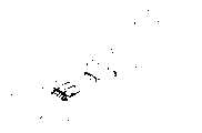
图1是本实用新型连接器组件的立体组合图。Fig. 1 is a three-dimensional assembled view of the connector assembly of the present invention.
图2是图1所示的音频输出装置的立体图。FIG. 2 is a perspective view of the audio output device shown in FIG. 1 .
图3是本实用新型连接器组件的未安装耳机组件时的部分立体分解图。Fig. 3 is a partial perspective exploded view of the connector assembly of the present invention when the earphone assembly is not installed.
图4是图3所示的连接器组件另一角度的视图。FIG. 4 is another perspective view of the connector assembly shown in FIG. 3 .
图5是图3所示的连接器组件进一步的立体分解示意图。FIG. 5 is a further perspective exploded view of the connector assembly shown in FIG. 3 .
图6是图5所示的连接器组件另一角度的视图。FIG. 6 is a view from another angle of the connector assembly shown in FIG. 5 .
图7是本实用新型连接器组件的第一连接器的立体图。Fig. 7 is a perspective view of the first connector of the connector assembly of the present invention.
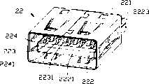
图8是本实用新型连接器组件的第二连接器的立体图。Fig. 8 is a perspective view of the second connector of the connector assembly of the present invention.
【具体实施方式】【Detailed ways】
请参阅图1及图2所示,本实用新型连接器组件1包括MP3播放器100及与播放器100相配合的音频输出装置200,该音频输出装置200包括扣合在播放器100上的端帽20及与端帽20相连的耳机组件30。1 and 2, the utility
请参阅图3至图6及图8,播放器100包括主体部10及装设在主体部一端的第一连接器12,其中主体部10呈一长方体,其前端面101上设有一可收容第一连接器12的凹部1010,且在主体部10的后端面102上设有一语音插孔(Audio Jack)1020,可与常规的使用语音插头连接的耳机相连接。第一连接器12包括第一绝缘本体122、收容在第一绝缘本体122内的导电元件及包覆在第一绝缘本体122上的第一遮蔽壳体121,本实施方式中该导电元件为一印刷电路板,该印刷电路板上设有四根第一导电片123及五根第二导电片124,其中第一导电片123的排列和间距符合现有USB公接口标准,可用作数据传输,实现传统MP3播放器的USB传输功能。第二导电片124中有三根用来实现音频信号的输出,分别为左声道、右声道及接地的作用,上述导电片123、124间隔排列,而且形成的整体接口可以与现有USB母接口相配接。所以,第一连接器12可以与电脑面板上所设USB母接口相连接,而利用第一导电片123进行数据传输。当然,第一连接器12的导电元件并不仅限于通过印刷电路板来实现,在其它实施方式中,亦可采用绝缘本体的舌板上装设导电端子来实现。但由于涉及到需在现有的USB标准端子间加设端子,在实施方式中采用印刷电路板的导电路径来实现更利于合理排布。Please refer to Fig. 3 to Fig. 6 and Fig. 8, the
MP3播放器100中还包括一些现有MP3播放器所需要的其它模块及连接元件,此处不详述。The
请参阅图3至图6及图7,端帽20包括帽体21及收容在帽体21内的第二连接器22,其中帽体21大体呈方形体,其设有前端面211、与前端面211相对的后端面212及两侧壁213、214,帽体21的前端面211设有一收容腔2110,后端面212上设有可让耳机线32穿过的通孔2120,并且帽体21的两侧壁213、214上分别延伸出两对相向设置且内侧成弧形状的凸块2151、2152,且两凸块2151、2152之间形成一弧形卡槽215;第二连接器22包括一第二绝缘本体222、组设在第二绝缘本体222上的四根第三导电端子223和五根第四导电端子224及包覆在第二绝缘本体222上的第二遮蔽壳体221,其中第三导电端子223的排列与间距符合现有USB母接口的标准,其包括接触部2231及尾部2232,第四导电端子224亦包括接触部2241及焊接部2242,且其中三根用来传输音频信号的音频端子,分别为左声道、右声道及接地的作用,本实施例中另外两根暂未使用。第二绝缘本体222包括一舌板2221及后部2223,在舌板2221上设有若干并列排布的端子收容槽,第三导电端子223和第四导电端子224间隔收容在上述收容槽内,且在后部2223上设有相对的上下两排收容槽以分别收容第三导电端子223的尾部2232和第四导电端子224的尾部2242。本实施例中四根第三端子223并未实现电性传输的功能,但其接触部2231可提供与第一连接器12相配合时增加连接可靠性的功能。Referring to Fig. 3 to Fig. 6 and Fig. 7, the
请参阅图1及图2,耳机组件30包括一挂绳31、耳机33及连接耳机33与第二连接器22的耳机线32,其中两耳机线32,是与挂绳31贴合并列,或可穿伸于挂绳31内,耳机线32的一端连接耳机33,另一端焊接至第二连接器22的其中三个音频端子224的尾部2242上以实现音频输出。耳机33包括杆部331及安装在杆部331上的听筒332。Please refer to Fig. 1 and Fig. 2,
在使用过程中,端帽20与播放器100对接即第一连接器12与第二连接器22对接,此时第二导电端子124与第四导电端子224相接触。挂绳31可挂在脖子上,开启播放器100就可以欣赏美妙的音乐,并且配合播放器100上设有的传统语音插孔1020可供二人共享音乐;在不听音乐时,可以将耳机33的杆部331卡扣在帽体20两侧的卡槽215内以固定耳机防止耳机晃动缠绕。During use, the
Claims (10)
Translated fromChinesePriority Applications (2)
| Application Number | Priority Date | Filing Date | Title |
|---|---|---|---|
| CNU200520072489XUCN2809969Y (en) | 2005-06-07 | 2005-06-07 | connector assembly |
| US11/446,691US7329153B2 (en) | 2005-06-07 | 2006-06-05 | Audio output device |
Applications Claiming Priority (1)
| Application Number | Priority Date | Filing Date | Title |
|---|---|---|---|
| CNU200520072489XUCN2809969Y (en) | 2005-06-07 | 2005-06-07 | connector assembly |
Publications (1)
| Publication Number | Publication Date |
|---|---|
| CN2809969Ytrue CN2809969Y (en) | 2006-08-23 |
Family
ID=36926151
Family Applications (1)
| Application Number | Title | Priority Date | Filing Date |
|---|---|---|---|
| CNU200520072489XUExpired - Fee RelatedCN2809969Y (en) | 2005-06-07 | 2005-06-07 | connector assembly |
Country Status (2)
| Country | Link |
|---|---|
| US (1) | US7329153B2 (en) |
| CN (1) | CN2809969Y (en) |
Families Citing this family (14)
| Publication number | Priority date | Publication date | Assignee | Title |
|---|---|---|---|---|
| US20060154530A1 (en)* | 2005-01-07 | 2006-07-13 | Novotney Donald J | Connector system |
| US7525216B2 (en)* | 2005-01-07 | 2009-04-28 | Apple Inc. | Portable power source to provide power to an electronic device via an interface |
| US7547218B2 (en)* | 2005-10-24 | 2009-06-16 | Super Talent Electronics Inc. | Plug and cap for a universal-serial-bus (USB) device |
| US7803016B2 (en) | 2006-06-20 | 2010-09-28 | Belkin International, Inc. | Electronic accessory for an MP3 player, and method of providing the same |
| US20080242147A1 (en)* | 2007-03-29 | 2008-10-02 | (Apple, Inc.) | Headset with data connector |
| US20090190277A1 (en)* | 2007-09-28 | 2009-07-30 | Super Talent Electronics, Inc. | ESD Protection For USB Memory Devices |
| US7789680B2 (en)* | 2007-07-05 | 2010-09-07 | Super Talent Electronics, Inc. | USB device with connected cap |
| US7635280B1 (en)* | 2008-07-30 | 2009-12-22 | Apple Inc. | Type A USB receptacle with plug detection |
| CN201773960U (en)* | 2008-09-30 | 2011-03-23 | 苹果公司 | Reduced size multi-pin header connector |
| US7575481B1 (en)* | 2008-12-24 | 2009-08-18 | Chen-Ya Liu | USB plug with a built-in-card-reading slot |
| CN102055086B (en)* | 2009-11-04 | 2014-09-24 | 富士康(昆山)电脑接插件有限公司 | Electrical connector and assembly method thereof |
| US8539125B1 (en) | 2011-02-18 | 2013-09-17 | Michael Ford | Combined USB flash drive cap audio device |
| TWM444637U (en)* | 2012-06-04 | 2013-01-01 | Power Quotient Int Co Ltd | Usb connector fixing element,connector body,substrate,sheltered housing assembly and its structure |
| EP3149965A1 (en)* | 2014-05-30 | 2017-04-05 | Sonova AG | An interface device, a cellular phone protection shell and an arrangement thereof |
Family Cites Families (20)
| Publication number | Priority date | Publication date | Assignee | Title |
|---|---|---|---|---|
| JPH11177250A (en)* | 1997-12-08 | 1999-07-02 | Sony Corp | Electronics |
| JP3810924B2 (en)* | 1998-08-28 | 2006-08-16 | 神鋼タセト株式会社 | Active flux composition for TIG welding |
| TW417859U (en)* | 1999-06-15 | 2001-01-01 | Hon Hai Prec Ind Co Ltd | Electric connector of easily automatic assembling |
| TW438168U (en)* | 1999-10-06 | 2001-05-28 | Liau Sheng Shing | Assembled structure of reeling box with replaceable switching socket |
| JP3652576B2 (en)* | 2000-03-09 | 2005-05-25 | アルプス電気株式会社 | Remote control device |
| US6305986B1 (en)* | 2000-05-18 | 2001-10-23 | Hon Hai Precision Ind. Co., Ltd. | Cable connector assembly having improved grounding means |
| AU2002251393A1 (en)* | 2002-03-14 | 2003-09-22 | Nokia Corporation | Accessory part for a mobile station |
| US7272667B2 (en)* | 2003-04-01 | 2007-09-18 | Pni Corporation | Portable and dedicated compact disk read-write unit |
| US7236751B2 (en)* | 2003-08-18 | 2007-06-26 | Alps Electric Co., Ltd. | Strap pendant with input buttons on strap for controlling attached portable devices |
| US7064964B2 (en)* | 2003-09-16 | 2006-06-20 | Tseng-Tien Peng | USB power amplified trumpet connecting device |
| AT500097B9 (en)* | 2003-10-17 | 2007-08-15 | Victorinox Ag | POCKET TOOL |
| US7070425B2 (en)* | 2003-12-10 | 2006-07-04 | Ennova Direct, Inc. | Thumb drive with retractable USB connector |
| US20050148313A1 (en)* | 2004-01-06 | 2005-07-07 | Chee Bill T.C. | Headset cord retainer |
| US7059914B2 (en)* | 2004-02-20 | 2006-06-13 | Advanced Connectek, Inc. | HDMI plug connector |
| US7097472B2 (en)* | 2004-09-08 | 2006-08-29 | Hewlett-Packard Development Company, L.P. | Universal serial bus plug |
| US7128617B2 (en)* | 2004-12-16 | 2006-10-31 | Advanced Connection Technology Inc. | Electrical socket assembly and plug connector coupled thereto |
| US7400859B2 (en)* | 2004-12-16 | 2008-07-15 | Intellectual Solutions, Inc. | Combined modulator and MP3 player having socket power supply adapter and/or universal connector |
| US7536565B2 (en)* | 2005-01-07 | 2009-05-19 | Apple Inc. | Techniques for improved playlist processing on media devices |
| US20060267994A1 (en)* | 2005-05-31 | 2006-11-30 | Lucent Technologies Inc. | Armrest personal digital media system |
| US7650007B2 (en)* | 2005-08-24 | 2010-01-19 | Apple Inc. | Lanyard for handheld electronic device |
- 2005
- 2005-06-07CNCNU200520072489XUpatent/CN2809969Y/ennot_activeExpired - Fee Related
- 2006
- 2006-06-05USUS11/446,691patent/US7329153B2/ennot_activeExpired - Fee Related
Also Published As
| Publication number | Publication date |
|---|---|
| US20060276062A1 (en) | 2006-12-07 |
| US7329153B2 (en) | 2008-02-12 |
Similar Documents
| Publication | Publication Date | Title |
|---|---|---|
| CN102263335B (en) | cable connector | |
| CN102394408B (en) | Cable connecting assembly | |
| CN201113076Y (en) | socket electrical connector | |
| JP3148334U (en) | ESATA connector with DC power pins | |
| CN201112707Y (en) | electrical connector | |
| CN2840402Y (en) | Electric connector | |
| CN201204275Y (en) | electrical connector | |
| CN2809969Y (en) | connector assembly | |
| CN2766363Y (en) | Electric connector | |
| CN201498796U (en) | cable connector | |
| US8202120B2 (en) | High frequency socket connector | |
| CN2665975Y (en) | Electric connector | |
| CN201252175Y (en) | Cable connector component | |
| CN2773936Y (en) | Electric connector | |
| CN201252288Y (en) | Electrical connector | |
| CN201478528U (en) | Cable connector component | |
| CN203481476U (en) | Cable connector assembly | |
| CN102544803A (en) | Cable connector component | |
| TWM359095U (en) | Electrical connector | |
| CN104348057A (en) | Cable connector assembly | |
| CN201498742U (en) | Cable Connector Assembly | |
| CN102117978A (en) | Electric connector | |
| JP3145526U (en) | Socket connector | |
| CN103972670A (en) | Cable connector subassembly | |
| CN217306859U (en) | Socket connector with plugging space and guiding structure |
Legal Events
| Date | Code | Title | Description |
|---|---|---|---|
| C14 | Grant of patent or utility model | ||
| GR01 | Patent grant | ||
| C17 | Cessation of patent right | ||
| CF01 | Termination of patent right due to non-payment of annual fee | Granted publication date:20060823 Termination date:20100607 |