CN2785316Y - Quickflashing memory and its USB interface protecting cover - Google Patents
Quickflashing memory and its USB interface protecting coverDownload PDFInfo
- Publication number
- CN2785316Y CN2785316YCNU2005200699811UCN200520069981UCN2785316YCN 2785316 YCN2785316 YCN 2785316YCN U2005200699811 UCNU2005200699811 UCN U2005200699811UCN 200520069981 UCN200520069981 UCN 200520069981UCN 2785316 YCN2785316 YCN 2785316Y
- Authority
- CN
- China
- Prior art keywords
- usb interface
- elastic element
- protective cover
- base
- flash memory
- Prior art date
- Legal status (The legal status is an assumption and is not a legal conclusion. Google has not performed a legal analysis and makes no representation as to the accuracy of the status listed.)
- Expired - Fee Related
Links
Images


Classifications
- H—ELECTRICITY
- H01—ELECTRIC ELEMENTS
- H01R—ELECTRICALLY-CONDUCTIVE CONNECTIONS; STRUCTURAL ASSOCIATIONS OF A PLURALITY OF MUTUALLY-INSULATED ELECTRICAL CONNECTING ELEMENTS; COUPLING DEVICES; CURRENT COLLECTORS
- H01R13/00—Details of coupling devices of the kinds covered by groups H01R12/70 or H01R24/00 - H01R33/00
- H01R13/46—Bases; Cases
- H01R13/52—Dustproof, splashproof, drip-proof, waterproof, or flameproof cases
- H01R13/5213—Covers
- H—ELECTRICITY
- H01—ELECTRIC ELEMENTS
- H01R—ELECTRICALLY-CONDUCTIVE CONNECTIONS; STRUCTURAL ASSOCIATIONS OF A PLURALITY OF MUTUALLY-INSULATED ELECTRICAL CONNECTING ELEMENTS; COUPLING DEVICES; CURRENT COLLECTORS
- H01R13/00—Details of coupling devices of the kinds covered by groups H01R12/70 or H01R24/00 - H01R33/00
- H01R13/46—Bases; Cases
- H01R13/502—Bases; Cases composed of different pieces
- H01R13/506—Bases; Cases composed of different pieces assembled by snap action of the parts
- H—ELECTRICITY
- H01—ELECTRIC ELEMENTS
- H01R—ELECTRICALLY-CONDUCTIVE CONNECTIONS; STRUCTURAL ASSOCIATIONS OF A PLURALITY OF MUTUALLY-INSULATED ELECTRICAL CONNECTING ELEMENTS; COUPLING DEVICES; CURRENT COLLECTORS
- H01R13/00—Details of coupling devices of the kinds covered by groups H01R12/70 or H01R24/00 - H01R33/00
- H01R13/46—Bases; Cases
- H01R13/502—Bases; Cases composed of different pieces
- H01R13/508—Bases; Cases composed of different pieces assembled by a separate clip or spring
- H—ELECTRICITY
- H01—ELECTRIC ELEMENTS
- H01R—ELECTRICALLY-CONDUCTIVE CONNECTIONS; STRUCTURAL ASSOCIATIONS OF A PLURALITY OF MUTUALLY-INSULATED ELECTRICAL CONNECTING ELEMENTS; COUPLING DEVICES; CURRENT COLLECTORS
- H01R13/00—Details of coupling devices of the kinds covered by groups H01R12/70 or H01R24/00 - H01R33/00
- H01R13/62—Means for facilitating engagement or disengagement of coupling parts or for holding them in engagement
- H01R13/627—Snap or like fastening
- H01R13/6275—Latching arms not integral with the housing
Landscapes
- Connector Housings Or Holding Contact Members (AREA)
- Details Of Connecting Devices For Male And Female Coupling (AREA)
Abstract
Description
Translated fromChinese【技术领域】【Technical field】
本实用新型涉及一种计算机外存储器,尤其是指一种具有USB接口的快闪存储器及其USB接口保护罩。The utility model relates to an external memory for a computer, in particular to a flash memory with a USB interface and a protective cover for the USB interface.
【背景技术】【Background technique】
USB快闪存储器是近年来发展起来的新一代计算机外存储器,由于其储存容量比一般的软盘大许多,而且数据交换速度快,无硬驱动设备,可实现热拔插,安全可靠,使用时只需把USB快闪存储器插到计算机或其它使用设备的USB接口上就可存取数据,而且其体积小、即插即拔、便于携带,深受用户欢迎,因此用USB存储器来取代传统的电脑软盘已是不可逆转的趋势。USB flash memory is a new generation of computer external memory developed in recent years. Because its storage capacity is much larger than that of ordinary floppy disks, and its data exchange speed is fast, there is no hard drive device, and it can be hot-swapped. It is safe and reliable. The data can be accessed by inserting the USB flash memory into the USB interface of the computer or other devices, and its small size, plug and play, easy to carry, is very popular among users, so the traditional computer is replaced by USB memory Floppy disks are an irreversible trend.
与本实用新型相关的现有技术可参照2004年公告的中国2624276Y号专利所揭示的USB存储器,该USB存储器包括一壳体、暴露在壳体端部的USB接口及套接在壳体端部的USB接口保护罩,然而其USB存储器的接口保护罩与USB接口只是简单套接,容易因震动或其他情况从USB接口滑落,而造成USB接口保护罩的丢失。The prior art related to the utility model can refer to the USB memory disclosed in the Chinese Patent No. 2624276Y announced in 2004. The USB memory includes a housing, a USB interface exposed at the end of the housing, and a However, the interface protective cover of the USB memory is simply socketed with the USB interface, and it is easy to slip off from the USB interface due to vibration or other conditions, resulting in the loss of the USB interface protective cover.
【实用新型内容】【Content of utility model】
本实用新型的目的在于提供一种快闪存储器及其USB接口保护罩,该USB接口保护罩可牢固地套接在快闪存储器的USB接口上、且能自USB接口上方便地取下。The purpose of the utility model is to provide a flash memory and its USB interface protective cover, the USB interface protective cover can be firmly socketed on the USB interface of the flash memory, and can be easily removed from the USB interface.
为实现上述目的,本实用新型采用如下技术方案:一种快闪存储器及其USB接口保护罩,其包括壳体、安装在壳体内的控制电路板及与控制电路板连接的USB接口,其中USB接口包括有金属外壳及收容在金属外壳内的对接座,USB接口的金属外壳包括一顶壁及底壁,顶壁与对接座之间为一收容腔,该顶壁上设有收容孔,上述USB接口保护罩设有一外壳、收容在外壳内的弹性元件及安装在外壳和弹性元件上的按钮,该弹性元件上设有突出部,当保护罩套接在USB接口上时,上述弹性元件的突出部伸入到USB接口的收容孔内,需要将保护罩自USB接口拔下时,压住按钮将弹性元件的突出部自USB接口上的收容孔中推出从而拔下USB接口保护罩。In order to achieve the above purpose, the utility model adopts the following technical solutions: a flash memory and its USB interface protection cover, which includes a housing, a control circuit board installed in the housing and a USB interface connected to the control circuit board, wherein the USB The interface includes a metal shell and a docking seat accommodated in the metal shell. The metal shell of the USB interface includes a top wall and a bottom wall. There is a receiving cavity between the top wall and the docking seat. The top wall is provided with a receiving hole. The USB interface protective cover is provided with a shell, an elastic element contained in the shell, and a button installed on the shell and the elastic element. The elastic element is provided with a protruding part. When the protective cover is sleeved on the USB interface, the above elastic element The protruding part extends into the receiving hole of the USB interface. When the protective cover needs to be pulled out from the USB interface, the button is pressed to push the protruding part of the elastic element out of the receiving hole on the USB interface so as to pull out the USB interface protective cover.
相较于现有技术,本实用新型快闪存储器具有如下功效:本实用新型的USB接口保护罩套接在快闪存储器的USB接口上时,接口保护罩的弹性元件的突出部伸入到USB接口的收容孔内,从而可以将保护罩牢固地套接在USB接口上,避免了保护罩从接口上脱落情况的发生;需要将保护罩自USB接口拔下时,只要按住其按钮即可将保护罩从USB接口上方便地拔下。Compared with the prior art, the flash memory of the utility model has the following effects: when the USB interface protective cover of the utility model is sleeved on the USB interface of the flash memory, the protruding part of the elastic element of the interface protective cover extends into the USB In the receiving hole of the interface, the protective cover can be firmly set on the USB interface, avoiding the occurrence of the protective cover falling off from the interface; when the protective cover needs to be pulled out from the USB interface, just press and hold the button Easily detach the protective cover from the USB port.
【附图说明】【Description of drawings】
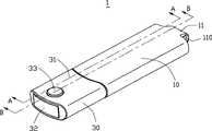
图1是本实用新型快闪存储器的立体组合图。FIG. 1 is a three-dimensional combined view of the flash memory of the present invention.
图2是图1所示的快闪存储器的部分分解图。FIG. 2 is a partially exploded view of the flash memory shown in FIG. 1 .
图3是本实用新型快闪存储器另一角度的部分分解图。FIG. 3 is a partially exploded view of another angle of the flash memory of the present invention.
图4是图1所示的快闪存储器的分解图。FIG. 4 is an exploded view of the flash memory shown in FIG. 1 .
图5是本实用新型快闪存储器另一角度的分解图。FIG. 5 is an exploded view from another angle of the flash memory of the present invention.
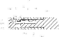
图6是本实用新型快闪存储器沿图1所示A-A线方向的局部剖视图。FIG. 6 is a partial cross-sectional view of the flash memory of the present invention along the line A-A shown in FIG. 1 .
图7是本实用新型快闪存储器沿图1所示B-B线方向的局部剖视图。FIG. 7 is a partial cross-sectional view of the flash memory of the present invention along the line B-B shown in FIG. 1 .
【具体实施方式】【Detailed ways】
请参照图1至图3所示,本实用新型快闪存储器及其USB接口保护罩1包括壳体10、安装在壳体内的电路板40(图4示)、与电路板连接的USB接口20及套接在USB接口上的USB接口保护罩30。Please refer to Fig. 1 to shown in Fig. 3, the flash memory of the present utility model and USB interface
壳体10纵长延伸,为携带方便,其一端设置有凸出部11,凸出部11上设有通孔110,使用时,可以将挂绳系在通孔110上,将该USB快闪存储器更方便地随身携带。在壳体的另一端为USB接口20,USB接口20包括一金属外壳21及收容在外壳内的对接座22。金属外壳21的包括一顶壁210及一底壁212,在顶壁212与对接座22之间为一收容腔211,该收容腔212用以收容对接USB插座(未图示)。安装在壳体10内的电路板的一端深入到上述收容腔212内,以与对接USB插座电性连接。在USB接口20的预壁210上设有一对通孔213。The
如图4至图7所示,USB接口保护罩30包括一个外壳31、由该外壳31围设而成的收容空间316、安装在该收容空间316内的基座32及组装在外壳31和基座32上的按钮33。外壳31包括一顶壁310、一底壁312及相对的前壁313、后壁315和侧壁314,在顶壁310上设有一通孔311。外壳的前壁313、后壁315均开设有与收容空间316相连通的通孔317,侧壁314的内表面318上设有台阶319。As shown in Figures 4 to 7, the USB interface
基座32包括上表面320、下表面322及相对的前端部323、后端部325和侧面324。在侧面324与後端部325的过渡处设有一坡面326,侧面324上还设有凸起327。基座32向后水平伸出一弹性元件34,在弹性元件34的上方为一自基座32的上表面320凹设而成的凹槽321,在弹性元件34的下方的基座32上也设有一凹槽328。弹性元件34包括与基座32相连的基部340及自基部340伸出的一对弹性臂342,在该对弹性臂342的末端各设有一突出部343,在本实施例中该突出部343呈倒勾状。自基座32的后端部325还伸出有一对导引柱35,该对导引柱35位于弹性元件34的一对弹性臂342的外侧。另外,弹性元件34的基部340上也设有一个孔341与外壳31顶壁的通孔311相对齐。按钮33包括上下两部分,上部331的直径大于下部332的直径。The
如图6及图7所示且参照图4及图5,USB接口保护罩30还包括一个辅助弹性元件36,用以保证弹性元件34的弹性。在基座32上于弹性元件34的正下方设有一开口329用以收容辅助弹性元件36,凹槽328则位于弹性元件36与开口329之间。该辅助弹性元件36则包括收容在开口329内的基部360及自基部360向上倾斜伸出的一对弹性臂362,辅助弹性元件36的弹性臂362抵在弹性元件34的弹性臂342的下表面。As shown in FIG. 6 and FIG. 7 and referring to FIG. 4 and FIG. 5 , the USB interface
USB接口保护罩30的各部件组合时,首先是将辅助弹性元件36组装在基座32的开口329内,两者干涉配合,同时辅助弹性元件36的弹性臂362抵靠在弹性元件34的弹性臂342的下表面;其次,将基座32自外壳31前壁313的开口317安装在外壳31的收容空间316内,此过程中基座31侧面324的坡面326可起导引的作用,基座32完全组装在外壳31内后,坡面326与外壳31侧面内表面318上设置的台阶319相接触,内表面318也会对基座32侧面324上的凸起327以挤压,从而基座31与外壳32可牢固配合;最后,按钮33的下部332通过外壳31的通孔311进入到弹性元件34基部340的孔341内,且相互干涉配合,按钮的上部331部分暴露在外壳31的顶壁310外以便于使用者的操作。在弹性元件24的上下方基座32上设有凹槽321、328,这些凹槽保证了弹性元件34在竖直方向上的位移空间。When the components of the USB interface
USB接口保护罩30套接在USB接口20上时,保护罩30的导引柱35引导弹性元件34的弹性臂342进入到USB接口20的收容腔211内,弹性臂342上的突出部343则伸入到USB接口金属外壳21顶壁210的收容孔213内,从而将保护罩30牢固地扣合在USB接口20上;需要将保护罩30自USB接口20拔下时,使用者只需压住按钮33,按钮33通过其对弹性元件34基部340向下的压力而将弹性元件34的突出部343自USB接口20的收容孔213中推出,即可将保护罩30从USB接口20上方便地拔下。另外,在USB接口保护罩30多次的插拔过程中,由于辅助弹性元件36的弹性臂362抵靠在弹性元件34的弹性臂342的下表面,进一步保证了弹性元件34的弹性及其突出部342与USB接口20的收容孔213的牢固扣合。When the USB interface
相较于现有技术,本实用新型快闪存储器的USB接口保护罩30套接在USB接口20上时,其弹性元件34的突出部342伸入到USB接口20的收容孔213内,从而可以将保护罩30牢固地套接在USB接口20上,避免了保护罩30从USB接口上的脱落;需要将保护罩自USB接口拔下时,使用者则只要按住按钮33即可将保护罩30从USB接口20上方便地拔下。Compared with the prior art, when the USB interface
Claims (10)
Translated fromChinesePriority Applications (2)
| Application Number | Priority Date | Filing Date | Title |
|---|---|---|---|
| CNU2005200699811UCN2785316Y (en) | 2005-03-18 | 2005-03-18 | Quickflashing memory and its USB interface protecting cover |
| US11/384,879US7241153B2 (en) | 2005-03-18 | 2006-03-20 | Portable storage device with protective cap |
Applications Claiming Priority (1)
| Application Number | Priority Date | Filing Date | Title |
|---|---|---|---|
| CNU2005200699811UCN2785316Y (en) | 2005-03-18 | 2005-03-18 | Quickflashing memory and its USB interface protecting cover |
Publications (1)
| Publication Number | Publication Date |
|---|---|
| CN2785316Ytrue CN2785316Y (en) | 2006-05-31 |
Family
ID=36772276
Family Applications (1)
| Application Number | Title | Priority Date | Filing Date |
|---|---|---|---|
| CNU2005200699811UExpired - Fee RelatedCN2785316Y (en) | 2005-03-18 | 2005-03-18 | Quickflashing memory and its USB interface protecting cover |
Country Status (2)
| Country | Link |
|---|---|
| US (1) | US7241153B2 (en) |
| CN (1) | CN2785316Y (en) |
Cited By (4)
| Publication number | Priority date | Publication date | Assignee | Title |
|---|---|---|---|---|
| CN100566521C (en)* | 2007-03-07 | 2009-12-02 | 华硕电脑股份有限公司 | Portable disc |
| CN1835663B (en)* | 2005-03-18 | 2011-06-29 | 富士康(昆山)电脑接插件有限公司 | Flash memory and its USB interface protection cover |
| TWI416812B (en)* | 2009-01-09 | 2013-11-21 | Chi Mei Comm Systems Inc | Usb connector protective cover |
| CN104348022A (en)* | 2014-08-28 | 2015-02-11 | 美禄电子(深圳)有限公司 | Dust cover for USB (Universal Serial Bus) plug |
Families Citing this family (35)
| Publication number | Priority date | Publication date | Assignee | Title |
|---|---|---|---|---|
| US7544073B2 (en)* | 2004-02-26 | 2009-06-09 | Super Talent Electronics, Inc. | Universal serial bus (USB) flash drive with swivel cap functionalities with two locking positions |
| CA110970S (en)* | 2005-04-29 | 2007-12-27 | Springboard Retail Networks Inc | Data storage device |
| US7407390B1 (en) | 2005-05-16 | 2008-08-05 | Super Talent Electronics, Inc. | USB device with plastic housing having inserted plug support |
| KR100790154B1 (en)* | 2006-06-28 | 2008-01-02 | 삼성전자주식회사 | External device |
| US7473112B2 (en)* | 2006-07-07 | 2009-01-06 | Hon Hai Precision Ind. Co., Ltd. | Flash memory device with elastic member |
| US7568942B1 (en)* | 2007-02-07 | 2009-08-04 | Michael G. Lannon | Sleeve and coupler for electronic device |
| AU2008234414B2 (en)* | 2007-03-30 | 2012-03-22 | Leong, Kenneth Tak-Ming Mr | A cap for USB flash memory drives and Type-A connector plugs |
| US7364445B1 (en)* | 2007-04-13 | 2008-04-29 | Super Talent Electronics, Inc. | USB flash device with rubber cover |
| TWM329837U (en)* | 2007-06-15 | 2008-04-01 | Bandrich Inc | USB interface protecting structure and wireless network card thereof |
| FR2923660A1 (en)* | 2007-11-13 | 2009-05-15 | Neowave Soc Par Actions Simpli | Universal serial bus connection assembly i.e. universal serial bus key, for connecting e.g. auxiliary storage, to personal computer, has female device with mounting unit engaged in hole of male connector to retain connector in device |
| US8991402B2 (en) | 2007-12-18 | 2015-03-31 | Pax Labs, Inc. | Aerosol devices and methods for inhaling a substance and uses thereof |
| USD583816S1 (en)* | 2008-01-10 | 2008-12-30 | Callpod Inc. | Wireless transmitting and receiving device |
| US7794245B2 (en)* | 2008-03-06 | 2010-09-14 | Thompson Brian J | Universal protection cover cap for a USB plug |
| CN101630788B (en)* | 2008-07-18 | 2012-10-17 | 深圳富泰宏精密工业有限公司 | Plug |
| WO2010020010A1 (en)* | 2008-08-20 | 2010-02-25 | Mark Leslie Kewley | A system and method for providing promotional material to visitors at a venue |
| CN101662095A (en)* | 2008-08-29 | 2010-03-03 | 深圳富泰宏精密工业有限公司 | Protective cover of USB interface |
| TWI406179B (en)* | 2008-10-13 | 2013-08-21 | Phison Electronics Corp | Storage apparatus |
| US7686629B1 (en)* | 2008-10-27 | 2010-03-30 | Avio Corporation | Electronic device with a sliding protective cap |
| CN101752725B (en)* | 2008-12-16 | 2012-11-21 | 深圳富泰宏精密工业有限公司 | Universal serial bus (USB) joint protective cover |
| US7878865B2 (en)* | 2009-06-08 | 2011-02-01 | International Business Machines Corporation | Locking connector for engaging a USB receptacle |
| US8142212B2 (en) | 2009-06-10 | 2012-03-27 | Imation Corp. | Locking mechanisms and locking caps for USB connectors |
| TW201101604A (en)* | 2009-06-18 | 2011-01-01 | Ho E Screw & Hardware Co Ltd | Retractable USB flash drive |
| US8029299B1 (en)* | 2010-10-28 | 2011-10-04 | Ho E Screw & Hardware Co., Ltd. | Cover unit |
| US8206161B1 (en)* | 2011-02-24 | 2012-06-26 | Cheng Uei Precision Industry Co., Ltd. | Electrical connector assembly |
| USD673963S1 (en) | 2011-10-19 | 2013-01-08 | MIMOCO, Inc. | USB drive |
| USD673962S1 (en) | 2011-10-24 | 2013-01-08 | MIMOCO, Inc. | USB drive and card reader with body |
| USD720761S1 (en) | 2011-12-21 | 2015-01-06 | Wibu-Systems Ag | Computer peripheral device |
| CN103268995B (en)* | 2013-04-19 | 2016-06-29 | 华为终端有限公司 | USB device |
| US9430004B2 (en)* | 2013-09-27 | 2016-08-30 | Avago Technologies General Ip (Singapore) Pte. Ltd. | Pull tab with exchangeable identification marker for pluggable communications modules |
| US9160098B1 (en)* | 2014-06-20 | 2015-10-13 | Cheng Uei Precision Industry Co., Ltd. | Electrical connector |
| CN105374384B (en)* | 2014-08-29 | 2018-09-14 | 群联电子股份有限公司 | Portable disk |
| JP6713886B2 (en)* | 2016-09-13 | 2020-06-24 | 日本ルメンタム株式会社 | Optical module and transmission device |
| KR101949078B1 (en) | 2018-02-01 | 2019-02-15 | 김문수 | Usb memory apparatus for easily parts change |
| AR116722A1 (en) | 2018-10-08 | 2021-06-09 | Juul Labs Inc | ASSEMBLY OF CHARGE ADAPTER OF A VAPORIZER |
| JP7387407B2 (en)* | 2019-11-27 | 2023-11-28 | 日本航空電子工業株式会社 | connector assembly |
Family Cites Families (8)
| Publication number | Priority date | Publication date | Assignee | Title |
|---|---|---|---|---|
| US6508678B1 (en)* | 2000-08-31 | 2003-01-21 | Advanced Connecteck Inc. | Electrical connector assembly |
| US6522534B1 (en) | 2001-10-03 | 2003-02-18 | Speed Tech Corp. | Pen-type portable memory device |
| US6612853B2 (en) | 2001-12-05 | 2003-09-02 | Speed Tech Corp. | Extensible/retractable and storable portable memory device |
| JP2003243093A (en)* | 2002-02-21 | 2003-08-29 | Yazaki Corp | USB connector |
| KR200286123Y1 (en) | 2002-05-30 | 2002-08-22 | 하나 마이크론(주) | flash memory apparatus with single body type rotary cover |
| US6808400B2 (en) | 2002-10-18 | 2004-10-26 | Aiptek International Inc. | USB connector structure with protection means |
| US6999322B1 (en)* | 2004-07-29 | 2006-02-14 | Chant Sincere Co., Ltd. | Memory stick having a USB port |
| US7014490B1 (en)* | 2005-02-25 | 2006-03-21 | Yazaki Corporation | USB connector equipped with lock mechanism |
- 2005
- 2005-03-18CNCNU2005200699811Upatent/CN2785316Y/ennot_activeExpired - Fee Related
- 2006
- 2006-03-20USUS11/384,879patent/US7241153B2/ennot_activeExpired - Fee Related
Cited By (4)
| Publication number | Priority date | Publication date | Assignee | Title |
|---|---|---|---|---|
| CN1835663B (en)* | 2005-03-18 | 2011-06-29 | 富士康(昆山)电脑接插件有限公司 | Flash memory and its USB interface protection cover |
| CN100566521C (en)* | 2007-03-07 | 2009-12-02 | 华硕电脑股份有限公司 | Portable disc |
| TWI416812B (en)* | 2009-01-09 | 2013-11-21 | Chi Mei Comm Systems Inc | Usb connector protective cover |
| CN104348022A (en)* | 2014-08-28 | 2015-02-11 | 美禄电子(深圳)有限公司 | Dust cover for USB (Universal Serial Bus) plug |
Also Published As
| Publication number | Publication date |
|---|---|
| US7241153B2 (en) | 2007-07-10 |
| US20060211279A1 (en) | 2006-09-21 |
Similar Documents
| Publication | Publication Date | Title |
|---|---|---|
| CN2785316Y (en) | Quickflashing memory and its USB interface protecting cover | |
| CN202363681U (en) | Card edge connector | |
| CN100470953C (en) | electrical connector | |
| CN2770276Y (en) | Data storing device | |
| CN2785188Y (en) | Cable connector assembly | |
| CN201112917Y (en) | electrical connector | |
| US20150162686A1 (en) | Electric connector for flat conductor and assembly method for electric connector and flat conductor | |
| CN206097923U (en) | A multifunctional mobile storage device | |
| CN101872041A (en) | Photoelectric connector | |
| CN201142436Y (en) | electronic card connector | |
| CN2490620Y (en) | Card connector | |
| CN201303139Y (en) | Edge connector | |
| CN202259775U (en) | Card edge connector | |
| JP2011138773A (en) | Electrical connector | |
| CN201230107Y (en) | Electric connector | |
| CN203631861U (en) | A structure and combination of anti-dropping plug connector | |
| CN1835663A (en) | Fast flasher memory and USB interface protective cover | |
| CN202260032U (en) | Connector structure | |
| CN201075512Y (en) | electrical connector | |
| TWI467261B (en) | Optical connector | |
| CN102650716B (en) | Light connector | |
| CN109599703B (en) | Flexible circuit board golden finger connector and using method thereof | |
| CN201499403U (en) | Movable storage device and shell structure thereof | |
| CN2840600Y (en) | Mobile storing device | |
| CN201075486Y (en) | Module connector |
Legal Events
| Date | Code | Title | Description |
|---|---|---|---|
| C14 | Grant of patent or utility model | ||
| GR01 | Patent grant | ||
| C17 | Cessation of patent right | ||
| CF01 | Termination of patent right due to non-payment of annual fee | Granted publication date:20060531 Termination date:20100318 |