CN2768715Y - Improved artificial knee joint - Google Patents
Improved artificial knee jointDownload PDFInfo
- Publication number
- CN2768715Y CN2768715YCN 200520000814CN200520000814UCN2768715YCN 2768715 YCN2768715 YCN 2768715YCN 200520000814CN200520000814CN 200520000814CN 200520000814 UCN200520000814 UCN 200520000814UCN 2768715 YCN2768715 YCN 2768715Y
- Authority
- CN
- China
- Prior art keywords
- tibial base
- knee joint
- artificial knee
- liner
- femoral implant
- Prior art date
- Legal status (The legal status is an assumption and is not a legal conclusion. Google has not performed a legal analysis and makes no representation as to the accuracy of the status listed.)
- Expired - Lifetime
Links
Images


Landscapes
- Prostheses (AREA)
Abstract
Translated fromChinese
Description
Translated fromChinese技术领域technical field
本实用新型涉及一种改良结构的人工膝关节,特别是涉及一种运用于人体大腿骨及胫骨之间并搭配结合大腿骨的股骨植入物形成一让患者能有效恢复以往正常运动的改良结构的人工膝关节。The utility model relates to an artificial knee joint with an improved structure, in particular to an improved structure which is applied between the femur and the tibia of a human body and combined with a femur implant combined with the femur to form an improved structure for the patient to effectively recover the normal movement in the past artificial knee joint.
背景技术Background technique
传统人工膝关节在设计上是具有一植入于胫骨的胫骨基座,一配置于胫骨基座上的胫骨基座衬垫,以及一植入于大腿骨并可在胫骨基座衬垫曲面上运动的股骨植入物,在患者活动或行走时,大腿骨即会连动股骨植入物在胫骨基座衬垫的曲面上运动,以达到大腿骨与胫骨之间的弯曲状态,让患者的膝关节可恢复如手术前般的动作状态。但是,由于胫骨基座衬垫是固定于胫骨基座上,所以当大腿骨或胫骨有内外方向转动时,增加转动磨擦,也易让股骨植入物的髁部或胫骨基座衬垫的曲面损耗,在经一段时间后,患者又必须动手术更换。The traditional artificial knee joint is designed with a tibial base implanted in the tibia, a tibial base liner configured on the tibial base, and a tibial base liner implanted in the femur and can be placed on the curved surface of the tibial base liner. With the moving femoral implant, when the patient moves or walks, the femur will move along with the femoral implant on the curved surface of the tibial base liner to achieve the bending state between the femur and the tibia, allowing the patient's The knee joint can return to the state of motion as before the operation. However, since the tibial base liner is fixed on the tibial base, when the femur or tibia rotates in the internal and external direction, the rotational friction will be increased, and the condyle of the femoral implant or the curved surface of the tibial base liner will be easily distorted. Wear and tear, after a period of time, the patient must undergo surgery for replacement.
于是,有些业者为了解决上述的缺失,特在胫骨基座底部表面凸设有一圆形凸部(或圆形凹部),而在胫骨基座的承载部表面上设有圆形凹部(或圆形凸部),当大腿骨或胫骨有内外方向转动时,该胫骨基座衬垫底部的圆形凸部可在胫骨基座的圆形凹部上转动或/及平移,让胫骨基座衬垫可随大腿骨或胫骨内外方向转动而动作,让患者大腿骨或胫骨在内外方向转动上有明显改善。但是,由于胫骨基座衬垫的圆形凸部及胫骨基座的圆形凹部之间无任何阻挡结构,以致胫骨基座衬垫可在胫骨基座上自由转动(360度),当内外方向转动角度过大时,加上膝关节周围的软组织不平衡,易让胫骨基座衬垫及胫骨基座形成卡掣状态,造成患者的困扰。Therefore, in order to solve the above-mentioned deficiency, some manufacturers have specially provided a circular convex portion (or circular concave portion) on the bottom surface of the tibial base, and provided a circular concave portion (or circular concave portion) on the surface of the bearing part of the tibial base. convex part), when the femur or tibia rotates in the medial direction, the circular convex part at the bottom of the tibial base pad can rotate or/and translate on the circular concave part of the tibial base pad, so that the tibial base pad can It moves with the rotation of the femur or tibia in the internal and external direction, so that the patient's femur or tibia can significantly improve the rotation in the internal and external direction. However, since there is no blocking structure between the circular convex part of the tibial base liner and the circular concave part of the tibial base, the tibial base liner can rotate freely (360 degrees) on the tibial base, when the internal and external direction When the rotation angle is too large, and the soft tissue around the knee joint is unbalanced, the tibial base liner and tibial base are likely to form a stuck state, causing troubles for patients.
为此,中国台湾专利公告第588648号提出上列缺失的解决方案,该案主要提供一在胫骨基座衬垫的底部凸设有一凹孔,而胫骨基座的承载部适当位置处设有一凸部,在胫骨基座衬垫置放于胫骨基座上时,该凸部即位于凹孔中,并在凸部两侧与凹孔两侧壁尚预留有一动作空间,该凹孔在两者所预留的动作空间中摆动,让胫骨基座衬垫可随大腿骨或胫骨作内外方向转动时受到限制。For this reason, China Taiwan Patent Announcement No. 588648 proposes the solution of above-mentioned deficiency, and this case mainly provides a bottom that is protruded at the bottom of the tibial base liner and is provided with a concave hole, and the appropriate position of the bearing portion of the tibial base is provided with a protruding hole. When the tibial base liner is placed on the tibial base, the convex part is located in the concave hole, and there is still a movement space reserved on both sides of the convex part and the two sides of the concave hole. Swing in the action space reserved by the former, so that the tibial base liner can be limited when it can rotate with the femur or tibia in the internal and external directions.
但该方案设计仅提供胫骨基座衬垫内转动受限制范围的解决方案,而胫骨基座衬垫与胫骨基座则仍维持等形设计,因此,当聚乙烯材质制作的胫骨基座衬垫转动时,由于胫骨基座为金属材质制成,故胫骨基座衬垫下表面容易产生磨耗而导致过多磨屑产生(尤其是位于胫骨基座后缘位置),而此磨屑更会落入胫骨而造成骨溶蚀现象发生。However, this design only provides a solution for the limited range of rotation in the tibial base liner, while the tibial base liner and the tibial base still maintain a conformal design. Therefore, when the tibial base liner made of polyethylene material When rotating, since the tibial base is made of metal material, the lower surface of the tibial base pad is prone to abrasion, resulting in excessive wear debris (especially at the posterior edge of the tibial base), and the abrasive debris will fall into the Osteolysis occurs in the tibia.
由此可见,上述现有的人工膝关节仍存在有诸多的缺陷,而亟待加以进一步改进。为了解决人工膝关节存在的问题,相关厂商莫不费尽心思来谋求解决之道,但长久以来一直未见适用的设计被发展完成,而一般产品又没有适切的结构能够解决上述问题,此显然是相关业者急欲解决的问题。This shows that above-mentioned existing artificial knee joint still has many defectives, and urgently needs to be further improved. In order to solve the problems existing in artificial knee joints, relevant manufacturers have tried their best to find a solution, but no suitable design has been developed for a long time, and the general products do not have a suitable structure to solve the above problems, which is obvious. It is a problem that relevant industry players are eager to solve.
有鉴于上述现有的人工膝关节存在的缺陷,本设计人基于从事此类产品设计制造多年丰富的实务经验及专业知识,积极加以研究创新,以期创设一种新型结构的改良结构的人工膝关节,能够改进一般现有的改良结构的人工膝关节,使其更具有实用性。经过不断的研究、设计,并经反复试作样品及改进后,终于创设出确具实用价值的本实用新型。In view of the defects of the above-mentioned existing artificial knee joints, the designer actively conducts research and innovation based on years of rich practical experience and professional knowledge engaged in the design and manufacture of such products, in order to create a new type of artificial knee joint with an improved structure , can improve the general existing artificial knee joint with improved structure, making it more practical. Through continuous research, design, and after repeated trial samples and improvements, the utility model with practical value is finally created.
发明内容Contents of the invention
本实用新型的目的在于,克服现有的人工膝关节存在的缺陷,而提供一种新的改良结构的人工膝关节,所要解决的技术问题是使其可以限制胫骨基座衬垫转动且令胫骨基座衬垫降低磨耗,以达成胫骨基座衬垫减少产生磨屑而降低骨溶蚀现象发生,从而更加适于实用。The purpose of this utility model is to overcome the defects of the existing artificial knee joint and provide a new artificial knee joint with improved structure. The base liner reduces wear, so that the tibial base liner reduces wear debris and reduces bone erosion, which is more suitable for practical use.
本实用新型的目的及解决其技术问题是采用以下的技术方案来实现的。依据本实用新型提出的一种改良结构的人工膝关节,是配置于大腿骨及胫骨之间,并搭配一结合于大腿骨的股骨植入物形成一让使用者恢复以往正常运动的人工膝关节,该人工膝关节包括一具备二曲面供股骨植入物动作的胫骨基座衬垫以及一具备承载面供该胫骨基座衬垫容置的胫骨基座,其中,该胫骨基座的承载面面积是满足胫骨基座衬垫受股骨植入物连动的转动,且该胫骨基座大于胫骨基座衬垫的承载面剩余区域上设有一限制体,并在该胫骨基座衬垫对应该限制体具有左、右止挡缘以限制胫骨基座衬垫转动的活动槽。The purpose of this utility model and the solution to its technical problems are achieved by adopting the following technical solutions. According to the utility model, an artificial knee joint with an improved structure is arranged between the femur and the tibia, and is combined with a femoral implant combined with the femur to form an artificial knee joint that allows the user to resume normal movement in the past , the artificial knee joint includes a tibial base liner with two curved surfaces for the action of the femoral implant and a tibial base with a bearing surface for the tibial base liner to accommodate, wherein the bearing surface of the tibial base The area is to meet the rotation of the tibial base liner linked by the femoral implant, and the tibial base is larger than the remaining area of the bearing surface of the tibial base liner. There is a limiter, and the tibial base liner corresponds to The limiting body has left and right stop edges to limit the rotation of the tibial base liner.
本实用新型的目的及解决其技术问题还可以采用以下的技术措施来进一步实现。The purpose of this utility model and the solution to its technical problems can also be further realized by adopting the following technical measures.
前述的改良结构的人工膝关节,其中所述的胫骨基座衬垫上设有一组接股骨植入物的支轴体。In the aforementioned artificial knee joint with improved structure, the said tibial base liner is provided with a set of pivot bodies connected to the femoral implant.
前述的改良结构的人工膝关节,其中所述的胫骨基座是延伸有一与人体胫骨组接的中空植入柱,且该胫骨基座衬垫对应延伸有一置入中空植入柱内的定位柱。In the aforementioned artificial knee joint with improved structure, the tibial base is extended with a hollow implanted column that is assembled with the tibia of the human body, and the tibial base liner is correspondingly extended with a positioning column inserted into the hollow implanted column .
前述的改良结构的人工膝关节,其中所述的中空植入柱内径大于该定位柱外径,而具有定位柱活动空间以限制胫骨基座衬垫相对胫骨基座的直向移动范围。In the aforementioned artificial knee joint with improved structure, the inner diameter of the hollow implanted column is larger than the outer diameter of the positioning column, and there is a movable space for the positioning column to limit the linear movement range of the tibial base liner relative to the tibial base.
借由上述技术方案,本实用新型改良结构的人工膝关节至少具有下列优点:With the above-mentioned technical solution, the artificial knee joint with improved structure of the utility model has at least the following advantages:
本实用新型提供了一种可限制胫骨基座衬垫转动且令胫骨基座衬垫降低磨耗产生的人工膝关节,其主要通过该胫骨基座的承载面面积是满足胫骨基座衬垫受股骨植入物连动的转动,且该胫骨基座大于胫骨基座衬垫的承载面剩余区域上设有一限制体,并在该胫骨基座衬垫对应该限制体具有左、右止挡缘以限制胫骨基座衬垫转动的活动槽,藉以达成胫骨基座衬垫减少产生磨屑而降低骨溶蚀现象发生的功效。The utility model provides an artificial knee joint which can limit the rotation of the tibial base liner and reduce the wear and tear of the tibial base liner. The rotation of the implant is interlocked, and the tibial base is larger than the remaining area of the bearing surface of the tibial base liner. The movable slot restricts the rotation of the tibial base liner, so as to achieve the effect of the tibial base liner to reduce the generation of wear debris and reduce the occurrence of bone erosion.
综上所述,本实用新型特殊结构的人工膝关节,其可以限制胫骨基座衬垫转动且令胫骨基座衬垫降低磨耗,且能够达成胫骨基座衬垫减少产生磨屑而降低骨溶蚀现象。其具有上述诸多的优点及实用价值,并在同类产品中未见有类似的结构设计公开发表或使用而确属创新,其不论在结构上或功能上皆有较大的改进,在技术上有较大的进步,并产生了好用及实用的效果,且较现有的人工膝关节具有增进的多项功效,从而更加适于实用,而具有产业的广泛利用价值,诚为一新颖、进步、实用的新设计。To sum up, the artificial knee joint with the special structure of the present invention can limit the rotation of the tibial base liner and reduce the wear of the tibial base liner, and can reduce the wear debris of the tibial base liner and reduce bone erosion. Phenomenon. It has the above-mentioned many advantages and practical value, and there is no similar structural design publicly published or used in similar products, so it is indeed innovative. It has made great progress, and has produced easy-to-use and practical effects, and has improved multiple functions compared with the existing artificial knee joints, so it is more suitable for practical use, and has wide application value in the industry. It is a novelty and progress. , Practical new design.
上述说明仅是本实用新型技术方案的概述,为了能够更清楚了解本实用新型的技术手段,并可依照说明书的内容予以实施,以下以本实用新型的较佳实施例并配合附图详细说明如后。The above description is only an overview of the technical solution of the utility model. In order to understand the technical means of the utility model more clearly and implement it according to the contents of the specification, the following is a detailed description of the preferred embodiment of the utility model with accompanying drawings. back.
本实用新型的具体实施方式由以下实施例及其附图详细给出。The specific embodiment of the utility model is given in detail by the following examples and accompanying drawings.
附图说明Description of drawings
图1是本新型的外观立体示意图。Fig. 1 is a three-dimensional schematic diagram of the appearance of the present invention.
图2是本新型的结构分解示意图。Fig. 2 is a schematic diagram of an exploded structure of the present invention.
图3-1、图3-2是本新型的胫骨基座衬垫内转动动作示意图。Fig. 3-1 and Fig. 3-2 are schematic diagrams of the internal rotation of the tibial base pad of the present invention.
图4-1、图4-2是本新型的胫骨基座衬垫直向移动动作示意图。Fig. 4-1 and Fig. 4-2 are schematic diagrams of the vertical movement of the tibial base liner of the present invention.
图5是本新型的使用例示意图。Fig. 5 is a schematic diagram of a usage example of the present invention.
图6是本新型的另一实施例结构分解示意图。Fig. 6 is an exploded schematic diagram of another embodiment of the present invention.
图7是本新型的另一实施例的使用例示意图。Fig. 7 is a schematic view of another embodiment of the present invention.
10:胫骨基座衬垫 11、12:曲面10: Tibia
13:支轴体 14:活动槽13: Pivot body 14: Movable slot
141:左止挡缘 142:右止挡缘141: Left stop edge 142: Right stop edge
15:定位柱 20:胫骨基座15: Positioning column 20: Tibial base
21:承载面 22:限制体21: Bearing surface 22: Restricting body
23:植入柱 30:大腿骨23: implant column 30: femur
40:股骨植入物 50:胫骨40: Femoral Implant 50: Tibia
具体实施方式Detailed ways
以下结合附图及较佳实施例,对依据本实用新型提出的改良结构的人工膝关节其具体实施方式、结构、特征及其功效,详细说明如后。The specific implementation, structure, features and functions of the artificial knee joint with improved structure according to the utility model will be described in detail below with reference to the accompanying drawings and preferred embodiments.
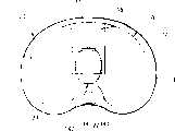
请参阅图1、图2、图5所示,是本新型外观立体、结构分解及使用例示意图。本实用新型是为一种改良结构的人工膝关节,是配置于大腿骨30及胫骨50之间,并搭配一结合于大腿骨30的股骨植入物40形成一让患者恢复以往正常运动的膝关节,该膝关节包含有一具备二曲面11、12供股骨植入物40动作的胫骨基座衬垫10及一具备承载面21供该胫骨基座衬垫10容置的胫骨基座20,本新型的第一实施例是通过该胫骨基座衬垫10上设有一组接股骨植入物40的支轴体13,使胫骨基座衬垫10以机构咬合机制受股骨植入物40连动。Please refer to Fig. 1, Fig. 2 and Fig. 5, which are schematic diagrams of the three-dimensional appearance, structural decomposition and usage examples of the new model. The utility model is an artificial knee joint with an improved structure, which is arranged between the
请参阅图6、图7所示,图6是本新型的另一实施例结构分解示意图,图7是本新型的另一实施例的使用例示意图。本新型的第二实施例则则是采紧密结合方式,使胫骨基座衬垫10以相对摩擦力受股骨植入物40连动,由于此两项连动方式均属习知技术,以下则不再赘述。Please refer to Fig. 6 and Fig. 7, Fig. 6 is an exploded schematic view of another embodiment of the present invention, and Fig. 7 is a schematic diagram of a use example of another embodiment of the present invention. The second embodiment of the present invention adopts a tight combination method, so that the
本新型主要通过该胫骨基座20的承载面21面积是满足胫骨基座衬垫10受股骨植入物40连动的转动,且该胫骨基座20大于胫骨基座衬垫10的承载面21剩余区域上设有一限制体22,并在该胫骨基座衬垫10对应该限制体22具有左、右止挡缘141、142以限制胫骨基座衬垫10转动的活动槽14,且该胫骨基座20是延伸有一与人体胫骨50组接的中空植入柱23,并在胫骨基座衬垫10对应延伸有一置入中空植入柱23内的定位柱15,前述中空植入柱23内径是大于该定位柱15外径而具有定位柱15活动空间,以限制胫骨基座衬垫10相对胫骨基座20的直向移动范围。The present model mainly satisfies the rotation of the
请参阅图3-1、图3-2所示,是本新型的内转动动作示意图。当人体大腿骨30或胫骨50运动而带动股骨植入物40连动胫骨基座衬垫10产生内转动状态时,由于本新型的胫骨基座衬垫10的承载面21上设有一限制体22,在胫骨基座衬垫10内转动时,将通过胫骨基座衬垫10的活动槽14以其两端左、右止挡缘141、142碰触限制体22而形成胫骨基座衬垫10内转动的限制范围,前述限制体22及活动槽14的形状及大小可依人体形状作不同模组设计,需注意的是,本新型的胫骨基座20面积是大于胫骨基座衬垫10面积,且该承载面21是满足胫骨基座衬垫10进行内转动动作时,该胫骨基座衬垫10仍不会超出该承载面21的剩余区域范围,藉此,除有效限制胫骨基座衬垫10转动外,更避免胫骨基座衬垫10内转动时,下表面不致与胫骨基座20边缘产生严重磨耗,且即使胫骨基座衬垫10内转动与胫骨基座20因微量滑动而有少许磨屑产生时,亦可降低该磨屑落入胫骨50而有效防止骨溶蚀现象产生。Please refer to Fig. 3-1 and Fig. 3-2, which are schematic diagrams of the inner rotation action of the present invention. When the
请参阅图4-1、图4-2所示,是本新型的直向移动动作实施例示意图,胫骨基座衬垫10受股骨植入物40连动时,除产生内转动外,亦会产生相对胫骨基座20的直向移动状态,为此,本新型将胫骨基座20接设胫骨50的植入柱23设计为中空状,且在胫骨基座衬垫10对应延伸有一置入中空植入柱23内的定位柱15,通过中空植入柱23内径是大于该定位柱15外径而具有定位柱15活动空间,藉此达成限制胫骨基座衬垫10相对胫骨基座20的直向移动范围,并搭配上述内转动限制说明,让病患术后的膝关节活动能维持最佳稳定的正常效能。Please refer to Figure 4-1 and Figure 4-2, which are schematic diagrams of the embodiment of the new type of straight movement action. To produce a state of straight movement relative to the
以上所述,仅是本实用新型的较佳实施例而已,并非对本实用新型作任何形式上的限制,虽然本实用新型已以较佳实施例揭露如上,然而并非用以限定本实用新型,任何熟悉本专业的技术人员,在不脱离本实用新型技术方案的范围内,当可利用上述揭示的技术内容作出些许更动或修饰为等同变化的等效实施例,但凡是未脱离本实用新型技术方案内容,依据本实用新型的技术实质对以上的实施例所作的任何简单修改、等同变化与修饰,均仍属于本实用新型技术方案的范围内。The above are only preferred embodiments of the present utility model, and do not limit the utility model in any form. Although the utility model has been disclosed as above with preferred embodiments, it is not intended to limit the utility model. Any Those skilled in the art, without departing from the scope of the technical solutions of the present utility model, may use the technical content disclosed above to make some changes or modify equivalent embodiments with equivalent changes, but all without departing from the technical solutions of the present utility model Solution content, any simple modifications, equivalent changes and modifications made to the above embodiments according to the technical essence of the utility model still belong to the scope of the utility model technical solution.
Claims (4)
Translated fromChinesePriority Applications (1)
| Application Number | Priority Date | Filing Date | Title |
|---|---|---|---|
| CN 200520000814CN2768715Y (en) | 2005-01-11 | 2005-01-11 | Improved artificial knee joint |
Applications Claiming Priority (1)
| Application Number | Priority Date | Filing Date | Title |
|---|---|---|---|
| CN 200520000814CN2768715Y (en) | 2005-01-11 | 2005-01-11 | Improved artificial knee joint |
Publications (1)
| Publication Number | Publication Date |
|---|---|
| CN2768715Ytrue CN2768715Y (en) | 2006-04-05 |
Family
ID=36689795
Family Applications (1)
| Application Number | Title | Priority Date | Filing Date |
|---|---|---|---|
| CN 200520000814Expired - LifetimeCN2768715Y (en) | 2005-01-11 | 2005-01-11 | Improved artificial knee joint |
Country Status (1)
| Country | Link |
|---|---|
| CN (1) | CN2768715Y (en) |
Cited By (19)
| Publication number | Priority date | Publication date | Assignee | Title |
|---|---|---|---|---|
| CN101697931B (en)* | 2009-09-30 | 2011-09-28 | 北京纳通投资有限公司 | Liner part knee-joint prosthesis, tibia part and knee-joint prosthesis |
| CN102232883A (en)* | 2010-04-23 | 2011-11-09 | 创生医疗器械(中国)有限公司 | Rotating platform false body for knee joint |
| CN103118635A (en)* | 2010-07-24 | 2013-05-22 | 捷迈有限公司 | Asymmetric Tibial Components for Knee Prostheses |
| CN104814815A (en)* | 2015-05-22 | 2015-08-05 | 北京爱康宜诚医疗器材股份有限公司 | Bone joint prosthesis |
| US9283082B2 (en) | 2010-07-24 | 2016-03-15 | Zimmer, Inc. | Methods related to seating of bearing component on tibial tray |
| US9308096B2 (en) | 2011-11-21 | 2016-04-12 | Zimmer, Inc. | Tibial baseplate with asymmetric placement of fixation structures |
| US9314343B2 (en) | 2010-09-10 | 2016-04-19 | Zimmer, Inc. | Motion facilitating tibial components for a knee prosthesis |
| US9381090B2 (en) | 2010-07-24 | 2016-07-05 | Zimmer, Inc. | Asymmetric tibial components for a knee prosthesis |
| CN107361883A (en)* | 2017-08-01 | 2017-11-21 | 北京安颂科技有限公司 | Cone locking knee-joint prosthesis |
| CN108186167A (en)* | 2018-01-23 | 2018-06-22 | 北京爱康宜诚医疗器材有限公司 | Knee-joint prosthesis |
| US10188530B2 (en) | 2010-12-17 | 2019-01-29 | Zimmer, Inc. | Provisional tibial prosthesis system |
| US10278827B2 (en) | 2015-09-21 | 2019-05-07 | Zimmer, Inc. | Prosthesis system including tibial bearing component |
| US10675153B2 (en) | 2017-03-10 | 2020-06-09 | Zimmer, Inc. | Tibial prosthesis with tibial bearing component securing feature |
| US10835380B2 (en) | 2018-04-30 | 2020-11-17 | Zimmer, Inc. | Posterior stabilized prosthesis system |
| US10898337B2 (en) | 2011-11-18 | 2021-01-26 | Zimmer, Inc. | Tibial bearing component for a knee prosthesis with improved articular characteristics |
| CN112741713A (en)* | 2019-10-31 | 2021-05-04 | 苏州微创关节医疗科技有限公司 | Tibial prosthesis and knee joint prosthesis |
| US11324599B2 (en) | 2017-05-12 | 2022-05-10 | Zimmer, Inc. | Femoral prostheses with upsizing and downsizing capabilities |
| US11324598B2 (en) | 2013-08-30 | 2022-05-10 | Zimmer, Inc. | Method for optimizing implant designs |
| US11426282B2 (en) | 2017-11-16 | 2022-08-30 | Zimmer, Inc. | Implants for adding joint inclination to a knee arthroplasty |
- 2005
- 2005-01-11CNCN 200520000814patent/CN2768715Y/ennot_activeExpired - Lifetime
Cited By (43)
| Publication number | Priority date | Publication date | Assignee | Title |
|---|---|---|---|---|
| CN101697931B (en)* | 2009-09-30 | 2011-09-28 | 北京纳通投资有限公司 | Liner part knee-joint prosthesis, tibia part and knee-joint prosthesis |
| CN102232883A (en)* | 2010-04-23 | 2011-11-09 | 创生医疗器械(中国)有限公司 | Rotating platform false body for knee joint |
| CN102232883B (en)* | 2010-04-23 | 2013-02-20 | 创生医疗器械(中国)有限公司 | Rotating platform false body for knee joint |
| US9763796B2 (en) | 2010-07-24 | 2017-09-19 | Zimmer, Inc. | Asymmetric tibial components for a knee prosthesis |
| US11224519B2 (en) | 2010-07-24 | 2022-01-18 | Zimmer, Inc. | Asymmetric tibial components for a knee prosthesis |
| US9192480B2 (en) | 2010-07-24 | 2015-11-24 | Zimmer, Inc. | Asymmetric tibial components for a knee prosthesis |
| CN103118635B (en)* | 2010-07-24 | 2015-11-25 | 捷迈有限公司 | Asymmetric Tibial Components for Knee Prostheses |
| US9283082B2 (en) | 2010-07-24 | 2016-03-15 | Zimmer, Inc. | Methods related to seating of bearing component on tibial tray |
| US9295557B2 (en) | 2010-07-24 | 2016-03-29 | Zimmer, Inc. | Asymmetric tibial components for a knee prosthesis |
| US10195041B2 (en) | 2010-07-24 | 2019-02-05 | Zimmer, Inc. | Asymmetric tibial components for a knee prosthesis |
| CN103118635A (en)* | 2010-07-24 | 2013-05-22 | 捷迈有限公司 | Asymmetric Tibial Components for Knee Prostheses |
| US9381090B2 (en) | 2010-07-24 | 2016-07-05 | Zimmer, Inc. | Asymmetric tibial components for a knee prosthesis |
| US12239540B2 (en) | 2010-07-24 | 2025-03-04 | Zimmer, Inc. | Asymmetric tibial components for a knee prosthesis |
| US10470889B2 (en) | 2010-07-24 | 2019-11-12 | Zimmer, Inc. | Asymmetric tibial components for a knee prosthesis |
| US9763794B2 (en) | 2010-07-24 | 2017-09-19 | Zimmer, Inc. | Tibial prosthesis |
| US9918844B2 (en) | 2010-07-24 | 2018-03-20 | Zimmer, Inc. | Tibial prosthesis with a fixed bearing component |
| US10543099B2 (en) | 2010-07-24 | 2020-01-28 | Zimmer, Inc. | Tibial prosthesis |
| US9861490B2 (en) | 2010-07-24 | 2018-01-09 | Zimmer, Inc. | Asymmetric tibial components for a knee prosthesis |
| US10413415B2 (en) | 2010-09-10 | 2019-09-17 | Zimmer, Inc. | Motion facilitating tibial components for a knee prosthesis |
| US9763795B2 (en) | 2010-09-10 | 2017-09-19 | Zimmer, Inc. | Motion facilitating tibial components for a knee prosthesis |
| US9314343B2 (en) | 2010-09-10 | 2016-04-19 | Zimmer, Inc. | Motion facilitating tibial components for a knee prosthesis |
| US11471288B2 (en) | 2010-09-10 | 2022-10-18 | Zimmer, Inc. | Motion facilitating tibial components for a knee prosthesis |
| US10188530B2 (en) | 2010-12-17 | 2019-01-29 | Zimmer, Inc. | Provisional tibial prosthesis system |
| US12383407B2 (en) | 2011-11-18 | 2025-08-12 | Zimmer, Inc. | Tibial bearing component for a knee prosthesis with improved articular characteristics |
| US10898337B2 (en) | 2011-11-18 | 2021-01-26 | Zimmer, Inc. | Tibial bearing component for a knee prosthesis with improved articular characteristics |
| US10265181B2 (en) | 2011-11-21 | 2019-04-23 | Zimmer, Inc. | Tibial baseplate with asymmetric placement of fixation structures |
| US9308096B2 (en) | 2011-11-21 | 2016-04-12 | Zimmer, Inc. | Tibial baseplate with asymmetric placement of fixation structures |
| US9707089B2 (en) | 2011-11-21 | 2017-07-18 | Zimmer, Inc. | Tibial baseplate with asymmetric placement of fixation structures |
| US11324598B2 (en) | 2013-08-30 | 2022-05-10 | Zimmer, Inc. | Method for optimizing implant designs |
| CN104814815A (en)* | 2015-05-22 | 2015-08-05 | 北京爱康宜诚医疗器材股份有限公司 | Bone joint prosthesis |
| US11160659B2 (en) | 2015-09-21 | 2021-11-02 | Zimmer, Inc. | Prosthesis system including tibial bearing component |
| US10278827B2 (en) | 2015-09-21 | 2019-05-07 | Zimmer, Inc. | Prosthesis system including tibial bearing component |
| US10675153B2 (en) | 2017-03-10 | 2020-06-09 | Zimmer, Inc. | Tibial prosthesis with tibial bearing component securing feature |
| US11547571B2 (en) | 2017-03-10 | 2023-01-10 | Zimmer, Inc. | Tibial prosthesis with tibial bearing component securing feature |
| US11324599B2 (en) | 2017-05-12 | 2022-05-10 | Zimmer, Inc. | Femoral prostheses with upsizing and downsizing capabilities |
| CN107361883A (en)* | 2017-08-01 | 2017-11-21 | 北京安颂科技有限公司 | Cone locking knee-joint prosthesis |
| CN107361883B (en)* | 2017-08-01 | 2019-07-09 | 北京安颂科技有限公司 | Cone locking knee-joint prosthesis |
| US11426282B2 (en) | 2017-11-16 | 2022-08-30 | Zimmer, Inc. | Implants for adding joint inclination to a knee arthroplasty |
| CN108186167B (en)* | 2018-01-23 | 2023-08-01 | 北京爱康宜诚医疗器材有限公司 | knee prosthesis |
| CN108186167A (en)* | 2018-01-23 | 2018-06-22 | 北京爱康宜诚医疗器材有限公司 | Knee-joint prosthesis |
| US10835380B2 (en) | 2018-04-30 | 2020-11-17 | Zimmer, Inc. | Posterior stabilized prosthesis system |
| US11911279B2 (en) | 2018-04-30 | 2024-02-27 | Zimmer, Inc. | Posterior stabilized prosthesis system |
| CN112741713A (en)* | 2019-10-31 | 2021-05-04 | 苏州微创关节医疗科技有限公司 | Tibial prosthesis and knee joint prosthesis |
Similar Documents
| Publication | Publication Date | Title |
|---|---|---|
| CN2768715Y (en) | Improved artificial knee joint | |
| CN201175391Y (en) | knee prosthesis | |
| CN103249378B (en) | Artificial knee joint | |
| JP6636480B2 (en) | Posterior stable orthopedic knee prosthesis with controlled condylar curvature | |
| CA2542975C (en) | Tibial knee prosthesis | |
| CN102112070B (en) | Total knee prosthesis | |
| US6436146B1 (en) | Implant for treating ailments of a joint or a bone | |
| US7922770B2 (en) | Total knee arthroplasty endoprosthesis with third condyle and rotating polyethylene insert | |
| CN101214175B (en) | Knee joint endoprosthesis | |
| JP2003319956A (en) | Wrist prosthesis | |
| JPH05501365A (en) | knee prosthesis | |
| CN102232883B (en) | Rotating platform false body for knee joint | |
| CA2107058A1 (en) | Continuous passive motion device for full extension of leg | |
| CN105496612B (en) | A kind of finger joint prosthesis | |
| US12138174B2 (en) | Implant for total wrist replacement | |
| Huson | Biomechanics of the tarsal mechanism. A key to the function of the normal human foot | |
| KR102568088B1 (en) | Total knee prosthesis with ceramic on ceramic friction torque and mobile ceramic plate | |
| CN100469337C (en) | Improved Artificial Knee Joint | |
| EP1352620A3 (en) | Prosthetic knee with limited sliding movement of tibial bearing | |
| CN111839825A (en) | Knee joint prosthesis | |
| CN209203636U (en) | Single condyle knee-joint prosthesis | |
| CN213076103U (en) | knee prosthesis | |
| CN215688798U (en) | All-trans wrist joint prosthesis capable of keeping ulnar and radial joint functions | |
| CN204072392U (en) | intervertebral device | |
| CN212522089U (en) | Palm and finger and interphalangeal joint prosthesis |
Legal Events
| Date | Code | Title | Description |
|---|---|---|---|
| C14 | Grant of patent or utility model | ||
| GR01 | Patent grant | ||
| ASS | Succession or assignment of patent right | Owner name:FARMA TECHNOLOGY CONSULTING CO., LTD. Free format text:FORMER OWNER: ZHENG CHENGGONG Effective date:20110803 | |
| C41 | Transfer of patent application or patent right or utility model | ||
| TR01 | Transfer of patent right | Effective date of registration:20110803 Address after:No. 14, building 161, 1 public welfare Road, Taichung City, Taiwan, China Patentee after:Fama Technology Consulting Co., Ltd. Address before:Taiwan, China Patentee before:Zheng Chenggong | |
| C17 | Cessation of patent right | ||
| CX01 | Expiry of patent term | Expiration termination date:20150111 Granted publication date:20060405 |