CN2625920Y - Optical transmission device - Google Patents
Optical transmission deviceDownload PDFInfo
- Publication number
- CN2625920Y CN2625920YCNU032515898UCN03251589UCN2625920YCN 2625920 YCN2625920 YCN 2625920YCN U032515898 UCNU032515898 UCN U032515898UCN 03251589 UCN03251589 UCN 03251589UCN 2625920 YCN2625920 YCN 2625920Y
- Authority
- CN
- China
- Prior art keywords
- optical
- isolator
- transmission
- mentioned
- coupling mechanism
- Prior art date
- Legal status (The legal status is an assumption and is not a legal conclusion. Google has not performed a legal analysis and makes no representation as to the accuracy of the status listed.)
- Expired - Fee Related
Links
Images


Landscapes
- Optical Couplings Of Light Guides (AREA)
Abstract
Description
Translated fromChinese技术领域technical field
本实用新型涉及一种光传输装置,尤其涉及一种运用一耦合器与一隔离器相互搭配连接而形成的光传输接合器。The utility model relates to an optical transmission device, in particular to an optical transmission joint formed by using a coupler and an isolator to cooperate with each other.
背景技术Background technique
一般公知的光传输装置如图1所示,包括:两个光传输设备1、3及一光缆2,上述光传输设备1、3分别设有一光发射端11、31及一光接收端12、32,上述光发射端11将光信号发送到与其连接的连接线13,再通过与上述连接线13连接的接线板15传送到光缆2中的一光纤21,上述光纤21将光信号传至另一接线板35,再通过接线板35所连接的连接线34,最后将光信号传至对应设置的另一光传输设备3的光接收端32;而上述光传输设备3的光发射端31则同样将光信号传向其所连接的一连接线33,再通过与上述连接线33连接的接线板35,传向光缆2中的另一光纤22,上述光纤22将光信号传至上述接线板15,再通过与接线板15所连接的连接线14,最后将光信号传至对应设置的上述光传输设备1的光接收端12。通过上述光传输设备1、3和光缆2中的两条光纤21、22相互对应设置,实现光信号的双向传输。然而上述装置虽具有光信号双向传输的功效,但在使用时,因需使用两条光纤才能实现,在实际使用时,将需要使用较多的、价格昂贵的光纤,且整体安装时也相对耗费工时。Generally known optical transmission device as shown in Figure 1, comprises: two optical transmission equipment 1,3 and an optical cable 2, above-mentioned optical transmission equipment 1,3 is respectively provided with an optical transmitting end 11,31 and an optical receiving end 12, 32. The above-mentioned optical transmitting end 11 sends the optical signal to the connection line 13 connected to it, and then transmits the optical signal to an optical fiber 21 in the optical cable 2 through the terminal block 15 connected to the above-mentioned connection line 13, and the above-mentioned optical fiber 21 transmits the optical signal to another A wiring board 35, and then through the connection line 34 connected to the wiring board 35, the optical signal is finally transmitted to the optical receiving end 32 of another optical transmission device 3 correspondingly arranged; and the optical transmitting end 31 of the above optical transmission device 3 is then Similarly, the optical signal is transmitted to a connecting line 33 connected thereto, and then passed to another optical fiber 22 in the optical cable 2 by the terminal block 35 connected with the above-mentioned connecting line 33, and the above-mentioned optical fiber 22 transmits the optical signal to the above-mentioned terminal block 15, and then through the connection line 14 connected to the wiring board 15, the optical signal is finally transmitted to the optical receiving end 12 of the above-mentioned optical transmission device 1 that is set correspondingly. Two-way transmission of optical signals is realized by the above-mentioned optical transmission devices 1, 3 and the two optical fibers 21, 22 in the optical cable 2 being arranged in correspondence with each other. However, although the above-mentioned device has the effect of two-way transmission of optical signals, it needs to use two optical fibers to realize it when in use. In actual use, it will need to use more and expensive optical fibers, and the overall installation is relatively expensive. working hours.
实用新型内容Utility model content
本实用新型的主要目的是提供一种光传输装置,仅使用光缆中的一根光纤,即可实现光信号的双向传输,具有降低成本及安装方便的特点。The main purpose of the utility model is to provide an optical transmission device, which can realize two-way transmission of optical signals by using only one optical fiber in the optical cable, and has the characteristics of low cost and convenient installation.
为实现上述目的,本实用新型提供一种光传输装置,其包括:两个光传输设备、两个传输接合器及一光缆,各光传输设备均设有一光发射端及一光接收端,分别与一传输接合器连接,而上述两个传输接合器之间通过上述光缆连接;上述传输接合器,由一耦合器与一隔离器相互搭配连接而成,隔离器T端与上述光传输设备的光发射端连接,隔离器T1端与耦合器C1端连接,耦合器C2端通过接收R端与上述光传输设备的光接收端连接,耦合器C端与光缆连接;光信号由光传输设备的光发射端经隔离器T端进入,经耦合器从耦合器C端传出,通过上述光缆中的一光纤,将光信号传送到另一传输接合器的耦合器C端,光信号通过耦合器C1端及隔离器T1,受到隔离器单向传输通路的阻挡,无法传向隔离器T端,光信号通过耦合器C2端及接收R端,传送到与接收R端连接的光传输设备的光接收端。In order to achieve the above object, the utility model provides an optical transmission device, which includes: two optical transmission devices, two transmission adapters and an optical cable, each optical transmission device is provided with an optical transmitting end and an optical receiving end, respectively It is connected with a transmission adapter, and the above two transmission adapters are connected through the above-mentioned optical cable; the above-mentioned transmission adapter is formed by matching and connecting a coupler and an isolator, and the T end of the isolator is connected to the above-mentioned optical transmission equipment. The optical transmitting end is connected, the isolator T1 end is connected to the coupler C1 end, the coupler C2 end is connected to the optical receiving end of the above-mentioned optical transmission equipment through the receiving R end, and the coupler C end is connected to the optical cable; the optical signal is transmitted by the optical transmission equipment. The optical transmitting end enters through the T-end of the isolator, and is transmitted from the C-end of the coupler through the coupler. Through an optical fiber in the above-mentioned optical cable, the optical signal is transmitted to the C-end of the coupler of another transmission adapter, and the optical signal passes through the coupler. The C1 terminal and the isolator T1 are blocked by the one-way transmission path of the isolator and cannot be transmitted to the isolator T terminal. The optical signal is transmitted to the optical transmission device connected to the receiving R terminal through the coupler C2 terminal and the receiving R terminal. Receiving end.
上述传输接合器中的隔离器T端、耦合器C端及接收R端为光纤。The T terminal of the isolator, the C terminal of the coupler and the receiving R terminal of the above-mentioned transmission adapter are optical fibers.
上述传输接合器中的隔离器T端、耦合器C端及接收R端为含接头的连接线。The T terminal of the isolator, the C terminal of the coupler and the receiving R terminal of the above-mentioned transmission adapter are connection lines with joints.
上述耦合器C端与光缆中的光纤之间设有一供相互连接的接线板。A wiring board for mutual connection is provided between the C end of the coupler and the optical fiber in the optical cable.
上述传输接合器设置在光传输设备内。The above-mentioned transmission adapter is provided in the optical transmission equipment.
上述传输接合器设置为一单体。The above-mentioned transmission adapter is set as a single body.
上述传输接合器为制成一体的耦合器与隔离器。The above-mentioned transmission adapter is a coupler and an isolator integrated.
上述传输接合器的隔离器成一体地设置在光传输设备内,耦合器设置在光传输设备外,耦合器各端为含接头的连接线。The isolator of the above-mentioned transmission adapter is integrally arranged in the optical transmission equipment, the coupler is arranged outside the optical transmission equipment, and each end of the coupler is a connection line with a connector.
上述传输接合器为单体设计,方便使用,并可在不改变现有设备下进行安装,增加整体的实用性及便利性。The above-mentioned transmission adapter is designed as a single body, which is convenient to use, and can be installed without changing the existing equipment, increasing the overall practicability and convenience.
上述传输接合器可直接设置在光传输设备内,从而减少外接插座数量,可避免接线错误的情况发生,并可降低制作成本,增加安全性及便利性。The above-mentioned transmission adapter can be directly arranged in the optical transmission equipment, thereby reducing the number of external sockets, avoiding wiring errors, reducing production costs, and increasing safety and convenience.
附图说明Description of drawings
图1为公知技术的使用示意图;Fig. 1 is the use schematic diagram of known technology;
图2为本实用新型第一实施例的立体分解图;Fig. 2 is a three-dimensional exploded view of the first embodiment of the utility model;
图3为本实用新型第一实施例传输接合器的示意图;Fig. 3 is a schematic diagram of the transmission adapter of the first embodiment of the present utility model;
图4为本实用新型第二实施例的组合示意图;Fig. 4 is the combination schematic diagram of the second embodiment of the present utility model;
图5为本实用新型第三实施例的组合示意图;Fig. 5 is a combined schematic view of the third embodiment of the utility model;
图6为本实用新型第四实施例的组合示意图;Fig. 6 is a combined schematic diagram of the fourth embodiment of the utility model;
图7为本实用新型第五实施例的组合示意图;Fig. 7 is a combined schematic view of the fifth embodiment of the utility model;
图8为本实用新型第六实施例的组合示意图;Fig. 8 is a combined schematic view of the sixth embodiment of the present invention;
图9为本实用新型第七实施例的组合示意图;Fig. 9 is a combined schematic view of the seventh embodiment of the present utility model;
图10为本实用新型第八实施例的组合示意图。Fig. 10 is a combined schematic view of the eighth embodiment of the present invention.
具体实施方式Detailed ways
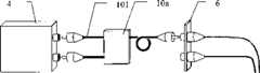
如图2和图3所示,本实用新型提供一种光传输装置,其包括:As shown in Figure 2 and Figure 3, the utility model provides an optical transmission device, which includes:
两个光传输设备4、8、两个传输接合器5、10及一光缆7,上述光传输设备4、8(如通信、网络设备)分别设置有一光发射端41、81及一光接收端42、82,分别与传输接合器5、10连接,而上述两个传输接合器5、10之间通过上述光缆7连接,用于信号传输。Two
上述传输接合器5,由一耦合器52与一隔离器51相互搭配连接而成,光信号由光传输设备4的光发射端41经隔离器T端511进入隔离器51,从隔离器T1端512传出,通过耦合器C1端521进入,再传往耦合器C端523;反之,由耦合器C端523进入的光信号向上述耦合器C1端521及耦合器C2端522传输,通过上述耦合器C1端521的光信号传过隔离器T1端512后,受到隔离器51的阻挡,光信号无法传向隔离器T端511,在隔离器51处形成单向传输通道;仅有耦合器C2端522会将光信号传至接收R端524,再由接收R端524传出光信号,上述接收R端524与上述光传输设备4的光接收端42连接。The above-mentioned transmission adapter 5 is formed by a
另,上述耦合器C端523与一接线板6结合,而上述接线板6另一端则与上述光缆7中的一光纤71相互连接,且上述光纤71另一端与一接线板9接合,再对应结合另一传输接合器10及光传输设备8,其设置方式与上述相同,在此不再赘述。In addition, the above-mentioned
上述传输接合器中的隔离器T端、耦合器C端及接收R端可以是一光纤,或是一含接头的连接线。The T terminal of the isolator, the C terminal of the coupler and the receiving R terminal of the above-mentioned transmission splicer may be an optical fiber, or a connection line with a connector.
上述结构构成一种光传输装置,如图2、图3所示,本实用新型的特点在于:两个光传输设备4、8上各设置一光发射端41、81及光接收端42、82,分别结合传输接合器5、10,在传输接合器5、10之间连接上述光缆7,根据上述传输接合器5(传输接合器10)内的一耦合器52与一隔离器51相互搭配,仅需使用光缆7中的单一光纤71,即可实现光信号双向传输的功效,不用象过去一样使用两条光纤,因而,大幅减少光纤的用量,进而降低整体成本。将上述传输接合器5、10分别制成一单体,便于使用,可在不改变现有设备下进行安装,而实现光信号双向传输的功效。另,上述传输接合器5、10可分别直接设置在光传输设备4、8内,可减少外接插座的数量,各仅需一个插座,不用再将光发射端及光接收端设置在光传输设备的外侧,故可避免接线错误的情况发生,并可降低制作成本,使得本实用新型具有使用光缆中的单一光纤,即可实现光信号双向传输、降低成本及方便安装等效果,增加了其实用性和便利性。Above-mentioned structure constitutes a kind of optical transmission device, as shown in Figure 2, Figure 3, the feature of the present utility model is: on two
如图2、图3所示,光信号由光传输设备4的光发射端41经上述传输接合器5的隔离器T端511进入,从隔离器T1端512传出,通过耦合器C1端521进入,再传向耦合器C端523,上述耦合器C端523则与接线板6结合,而上述接线板6另一端与上述光缆7中的一光纤71相互连接,且上述光纤71另一端与接线板9接合,再与另一传输接合器10,此时进入的光信号将受传输接合器10内隔离器(图未示)的阻挡,而使光信号传向上述光传输设备8的光接收端82。反之,光信号也可由光传输设备8的光发射端81经上述传输接合器10进入,而传至光传输设备4的光接收端42,使得仅需使用光缆中的单一光纤,即可实现光信号双向传输的目的。As shown in Figure 2 and Figure 3, the optical signal enters from the optical transmitting
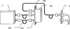
如图4所示,本实用新型在使用时可将上述传输接合器10a设为一单体,上述单体上设置有连接线101(或设置有连接线及接头),分别与光传输设备4及接线板6连接便于使用,并可在不改变现有设备下进行安装,而实现光信号双向传输的功效。如图5所示,上述传输接合器10b的单体上也可设置插座102,连接线106将上述接合器10b分别与光传输设备4及接线板6连接。如图6所示,上述传输接合器10c的单体上设置有插座102(或连接线),并设有可安装在配线架上的面板103,其连接方式与上述相似,可在不改变现有设备下进行安装,实现光信号双向传输的功效。As shown in Figure 4, when the utility model is in use, the above-mentioned
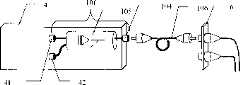
如图7所示,本实用新型在使用时可将上述传输接合器10d设置在光传输设备4内成为一单体;如图8所示,上述传输接合器10e采用一耦合器52与一隔离器51相互搭配连接而成一单体,并设置在光传输设备4内;或采用耦合器与隔离器一体制成的单体105,即传输接合器10f(请参阅图9),如此可以减少外接插座数量,仅需一个插座104即可,不用再将光发射端41及光接收端42设置在光传输设备4外侧,可避免接线错误的情况发生,并可降低制作成本。另一种组成传输接合器10g的方式是,仅将隔离器51设置在光传输设备4内(请参阅图10),并外置耦合器52,耦合器52各端为一含接头的连接线101。As shown in Figure 7, when the utility model is in use, the above-mentioned transmission adapter 10d can be arranged in the
Claims (8)
Priority Applications (1)
| Application Number | Priority Date | Filing Date | Title |
|---|---|---|---|
| CNU032515898UCN2625920Y (en) | 2003-05-08 | 2003-05-08 | Optical transmission device |
Applications Claiming Priority (1)
| Application Number | Priority Date | Filing Date | Title |
|---|---|---|---|
| CNU032515898UCN2625920Y (en) | 2003-05-08 | 2003-05-08 | Optical transmission device |
Publications (1)
| Publication Number | Publication Date |
|---|---|
| CN2625920Ytrue CN2625920Y (en) | 2004-07-14 |
Family
ID=34253228
Family Applications (1)
| Application Number | Title | Priority Date | Filing Date |
|---|---|---|---|
| CNU032515898UExpired - Fee RelatedCN2625920Y (en) | 2003-05-08 | 2003-05-08 | Optical transmission device |
Country Status (1)
| Country | Link |
|---|---|
| CN (1) | CN2625920Y (en) |
Cited By (7)
| Publication number | Priority date | Publication date | Assignee | Title |
|---|---|---|---|---|
| US8184940B2 (en) | 2004-06-18 | 2012-05-22 | Adc Telecommunications, Inc. | Telecommunications cabinet with connector storage |
| CN103676043A (en)* | 2012-09-04 | 2014-03-26 | 湖北省电力公司孝感供电公司 | Connection method for quick optical path communication |
| CN106768275A (en)* | 2016-12-16 | 2017-05-31 | 善测(天津)科技有限公司 | A kind of optical fiber Tip timing sensor extended line |
| US10067309B2 (en) | 1999-03-01 | 2018-09-04 | Commscope Technologies Llc | Optical fiber distribution frame with outside plant enclosure |
| US10151896B2 (en) | 2003-07-02 | 2018-12-11 | CommScope Technologies, LLC | Telecommunications connection cabinet |
| US10168491B2 (en) | 2003-06-30 | 2019-01-01 | Commscope Technologies Llc | Fiber optic connector holder and method |
| US10393980B2 (en) | 2003-11-17 | 2019-08-27 | Commscope Technologies Llc | Fiber distribution device |
- 2003
- 2003-05-08CNCNU032515898Upatent/CN2625920Y/ennot_activeExpired - Fee Related
Cited By (26)
| Publication number | Priority date | Publication date | Assignee | Title |
|---|---|---|---|---|
| US10067309B2 (en) | 1999-03-01 | 2018-09-04 | Commscope Technologies Llc | Optical fiber distribution frame with outside plant enclosure |
| US11119285B2 (en) | 2003-06-30 | 2021-09-14 | Commscope Technologies Llc | Fiber optic connector holder and method |
| US10634860B2 (en) | 2003-06-30 | 2020-04-28 | Commscope Technologies Llc | Fiber optic connector holder and method |
| US10168491B2 (en) | 2003-06-30 | 2019-01-01 | Commscope Technologies Llc | Fiber optic connector holder and method |
| US10371915B2 (en) | 2003-07-02 | 2019-08-06 | Commscope Technologies Llc | Telecommunications connection cabinet |
| US10782497B2 (en) | 2003-07-02 | 2020-09-22 | Commscope Technologies Llc | Telecommunications connection cabinet |
| US10527809B2 (en) | 2003-07-02 | 2020-01-07 | Commscope Technologies Llc | Telecommunications connection cabinet |
| US10436998B2 (en) | 2003-07-02 | 2019-10-08 | Commscope Technologies Llc | Telecommunications connection cabinet |
| US10151896B2 (en) | 2003-07-02 | 2018-12-11 | CommScope Technologies, LLC | Telecommunications connection cabinet |
| US11579390B2 (en) | 2003-11-17 | 2023-02-14 | Commscope Technologies Llc | Fiber distribution device |
| US10782498B2 (en) | 2003-11-17 | 2020-09-22 | Commscope Technologies Llc | Fiber distribution device |
| US10393980B2 (en) | 2003-11-17 | 2019-08-27 | Commscope Technologies Llc | Fiber distribution device |
| US9341798B2 (en) | 2004-06-18 | 2016-05-17 | Commscope Technologies Llc | Telecommunications cabinet with connector storage |
| US10809467B2 (en) | 2004-06-18 | 2020-10-20 | Commscope Technologies Llc | Telecommunications cabinet with connector storage |
| US10274686B2 (en) | 2004-06-18 | 2019-04-30 | Commscope Technologies Llc | Telecommunications cabinet with connector storage |
| US10126509B2 (en) | 2004-06-18 | 2018-11-13 | Commscope Technologies Llc | Telecommunications cabinet with connector storage |
| US8538228B2 (en) | 2004-06-18 | 2013-09-17 | Adc Telecommunications, Inc. | Telecommunications cabinet with connector storage |
| US8184940B2 (en) | 2004-06-18 | 2012-05-22 | Adc Telecommunications, Inc. | Telecommunications cabinet with connector storage |
| US9201206B2 (en) | 2004-06-18 | 2015-12-01 | Commscope Emea Limited | Telecommunications cabinet with connector storage |
| US10634859B2 (en) | 2004-06-18 | 2020-04-28 | Commscope Technologies Llc | Fiber optic connector holder unit |
| US8818158B2 (en) | 2004-06-18 | 2014-08-26 | Adc Telecommunications, Inc. | Telecommunications cabinet with connector storage |
| CN101713852B (en)* | 2004-06-18 | 2014-04-23 | Adc电信公司 | Multi-position fiber optic connector bracket and method for storing fiber optic connectors in a telecommunications connection cabinet |
| US10345539B2 (en) | 2004-06-18 | 2019-07-09 | Commscope Technologies Llc | Telecommunications cabinet with connector storage |
| US11428876B2 (en) | 2004-06-18 | 2022-08-30 | Commscope Technologies Llc | Telecommunications cabinet with connector storage |
| CN103676043A (en)* | 2012-09-04 | 2014-03-26 | 湖北省电力公司孝感供电公司 | Connection method for quick optical path communication |
| CN106768275A (en)* | 2016-12-16 | 2017-05-31 | 善测(天津)科技有限公司 | A kind of optical fiber Tip timing sensor extended line |
Similar Documents
| Publication | Publication Date | Title |
|---|---|---|
| CN102870027B (en) | Quad small form factor pluggable (QSFP) adapter module | |
| CN105608031B (en) | For promoting the integrated circuit of the optic communication between electronic device | |
| US8403571B2 (en) | Apparatuses, systems, and methods for facilitating optical communication between electronic devices | |
| DK1360593T3 (en) | Configurable, connector-based I / O system | |
| CN2625920Y (en) | Optical transmission device | |
| US20170068061A1 (en) | Detachable high-speed transmission cable and module thereof | |
| CN109994281B (en) | AOC cable compatible with multiple interfaces | |
| CN102033267B (en) | Optical fiber jumper and optical distribution frame | |
| CN204719272U (en) | High-speed transmission cable module and high-speed transmission device | |
| CN201215592Y (en) | Flexible metal sleeve type optical fiber connection construction | |
| CN103368025A (en) | Apparatus for transmitting high speed data via a cable | |
| CN207869251U (en) | A kind of HDMI Transmission systems with optical connector | |
| CN210670386U (en) | Transmission system for transmitting DVI signals in long distance by optical fiber | |
| CN210666112U (en) | A passive optical fiber conversion device | |
| CN207571342U (en) | Optical Fiber Transmission Device | |
| CN111182277B (en) | Transmission system for DVI signals over long distances using optical fiber | |
| CN222638577U (en) | HDMI signal transmission device with MPO interface | |
| TWI802287B (en) | Small form-factor pluggable transceiver | |
| CN101156336B (en) | Electrooptical coupling device | |
| KR102355876B1 (en) | Optical Connector | |
| CN2899341Y (en) | DVI digital video optical-fiber receiver-transmitter converter | |
| CN217883645U (en) | Video signal transmission system with optical fibers connected | |
| CN116707565B (en) | Small form factor pluggable transceiver | |
| CN217770086U (en) | Optical module and transmission system | |
| CN2657309Y (en) | Optical fibre network camera |
Legal Events
| Date | Code | Title | Description |
|---|---|---|---|
| C14 | Grant of patent or utility model | ||
| GR01 | Patent grant | ||
| C19 | Lapse of patent right due to non-payment of the annual fee | ||
| CF01 | Termination of patent right due to non-payment of annual fee |