CN2606979Y - Novel portable equipment intelligent charger - Google Patents
Novel portable equipment intelligent chargerDownload PDFInfo
- Publication number
- CN2606979Y CN2606979YCN 02282403CN02282403UCN2606979YCN 2606979 YCN2606979 YCN 2606979YCN 02282403CN02282403CN 02282403CN 02282403 UCN02282403 UCN 02282403UCN 2606979 YCN2606979 YCN 2606979Y
- Authority
- CN
- China
- Prior art keywords
- charging
- circuit
- links
- portable set
- charging current
- Prior art date
- Legal status (The legal status is an assumption and is not a legal conclusion. Google has not performed a legal analysis and makes no representation as to the accuracy of the status listed.)
- Expired - Lifetime
Links
- 239000004065semiconductorSubstances0.000claimsdescription5
- WHXSMMKQMYFTQS-UHFFFAOYSA-NLithiumChemical compound[Li]WHXSMMKQMYFTQS-UHFFFAOYSA-N0.000description4
- 229910052744lithiumInorganic materials0.000description4
- 238000010586diagramMethods0.000description2
- HBBGRARXTFLTSG-UHFFFAOYSA-NLithium ionChemical compound[Li+]HBBGRARXTFLTSG-UHFFFAOYSA-N0.000description1
- 239000003990capacitorSubstances0.000description1
- 238000005516engineering processMethods0.000description1
- 239000012467final productSubstances0.000description1
- 229910001416lithium ionInorganic materials0.000description1
- 230000014759maintenance of locationEffects0.000description1
- 238000000034methodMethods0.000description1
- 102220029346rs34541442Human genes0.000description1
- 238000003860storageMethods0.000description1
- 230000009466transformationEffects0.000description1
Images

Landscapes
- Charge And Discharge Circuits For Batteries Or The Like (AREA)
Abstract
Description
Technical field
The utility model relates to a kind of charging device of portable set, more particularly, relates to a kind of portable set charging device intelligent, that be provided with multiple charging current.
Background technology
Because information storages such as portable set such as palmtop PC are big, volume is little, easy to carry, so, extremely everybody favor always since it comes out.In order to make the portable set can be user-friendly better, long as electrification time, volume is little, in light weight, portable set generally all is built-in with jumbo lithium ion battery.
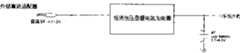
For ease of the portable set charging, present most of portable sets all are furnished with constant current constant voltage type lithium cell charging circuit simultaneously.As shown in Figure 1, the user only need link to each other portable set and gets final product by foreign current adapter EXDC with power supply.Its charging principle is: foreign current adapter EXDC at first converts the 220V alternating current to the 5V DC power supply, then, give the battery charge of portable set by built-in lithium cell charging circuit according to the mode of constant current constant voltage, that is: when the output voltage of EXDC during greater than 4.5V, charging circuit begins with a fixing current value charging, after the voltage of lithium battery reaches the magnitude of voltage of setting, transfer constant voltage charge again to, when charging current was less than the cut-off current value set by the time, whole charging process finished.
The shortcoming of this charging modes is: 1, charging approach is single, can only charge according to the pattern that producer provides.And, present develop rapidly along with computer standardization, the USB cable interface is seen everywhere, and USB interface itself just has direct current 5V power supply, so, if can make full use of the power supply of USB cable charges to portable set, promptly save outside DC adapter, saved cost, simplified operation, can increase the portable set charging modes again, it is more flexible to charge.2, charging current is fixing immutable, can not change charging current intelligently with different charging approach according to system mode.
Summary of the invention
In view of the foregoing, the purpose of this utility model provides a kind of charging device of intelligent portable set, this charging device can be portable set multiple different charging approach and charging current is provided, and can judge, control the action of charging circuit according to the running status of system intelligently.
For achieving the above object, the utility model is taked following design: a kind of novel portable device intelligence charging device, and it mainly is made up of USB interface, switching circuit, charging current selection/initialization circuit three parts of standard;
The power output end of described USB interface links to each other with the input of described switching circuit, the power input V of the charging circuit that the output of described switching circuit and portable set are joinedCCLink to each other;
The control end of described switching circuit links to each other with the power output end of the outside DC adapter that portable set is joined, and controls the conducting and the shutoff of described switching circuit;
The current settings end IPROM of the charging circuit that the signal output part of described charging current selection/initialization circuit and portable set are built-in links to each other; Its charging current selecting side links to each other with power output end, the portable set system mode output PWR-EN of outside DC adapter respectively.
Described switching circuit mainly comprises a switching tube, and this switching tube is connected on the power output end and the charging circuit power input V of described USB interfaceCCBetween, this control end of switching tube links to each other with the power output end of the outside DC adapter that portable set is joined.
Described charging current selection/initialization circuit comprises three tunnel charging current initialization circuits;
One the tunnel is charging circuit at a slow speed, and this circuit mainly comprises one first charging resistor, and an end of this charging resistor links to each other with ground, and the other end links to each other with the current settings end IPROM of charging circuit;
One the tunnel is quick-charging circuit, and this circuit comprises second charging resistor and the switching tube of mutual series connection; This quick-charging circuit is in parallel with first charging resistor; Described control end of switching tube links to each other with the power output end of the outside DC adapter that portable set is joined;
One the tunnel is the standard charging circuit, and this circuit mainly comprises the 3rd charging resistor, diode and the comparator of mutual series connection, and this charging circuit is in parallel with the switching tube of described quick-charging circuit; The input of described comparator links to each other with the system mode output of portable set.
The utility model changes charging current by changing charging resistor.
The utility model provides multiple charging modes for portable set, simultaneously, also can judge automatically, set charging current according to the operating state of different charging modes and portable set, makes charging modes more flexibly, conveniently.
Description of drawings
Fig. 1 is present portable set charging principle figure
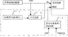
Fig. 2 is a theory diagram of the present utility model
Fig. 3 is physical circuit figure of the present utility model
Fig. 4 is the utility model charging principle flow chart
Embodiment
The utility model is not done any change to the structure of existing portable set such as palmtop PC, and made full use of its lithium cell charging circuit of joining, designed an intelligent charging device, this charging device has increased the function of utilizing USB cable to charge for portable set, automatically judge the charging approach simultaneously, and change charging current intelligently according to system mode, charging current is designed to quick charge, standard charging and the third gear of charging at a slow speed.
Fig. 2 is a theory diagram of the present utility model.As shown in the figure, the utility model mainly is made up ofusb 1,switching circuit 2, charging current selection/initialization circuit 3 three parts of standard.Its annexation is:
The power output end of describedusb 1 links to each other with the input ofswitching circuit 2, the power input V of the charging circuit that the output ofswitching circuit 2 and portable set are built-inCCLink to each other; In addition, the power input V of the built-in charging circuit of the power output end of the portable set outside DC adapter of joining and portable setCCAlso link to each other the conducting ofcontrol switch circuit 2 and shutoff when linking to each other with the control end ofswitching circuit 2;
The current settings end IPROM of the charging circuit that the signal output part of described charging current selection/initialization circuit 3 and portable set are built-in links to each other; Its charging current selecting side links to each other with power output end, the portable set system mode output PWR-EN of outside DC adapter respectively.Chargingcurrent initialization circuit 3 is by changing and the resistance of the charging resistor that the current settings end IPROM of the charging circuit that portable set is built-in links to each other changes charging current, charging current being designed to quick charge, standard charging and the third gear of charging at a slow speed.
Operation principle of the present utility model is: when the outside DC adapter EXDC that joins with portable set as the user provides power supply for the built-in charging circuit of portable set, theswitching circuit 2 that links to each other withusb 1 disconnects, so no matter whetherusb 1 links to each other with USB cable, portable set all is to provide working power V by outside DC adapter for its built-in charging circuitCCWhen the user does not link to each other outside DC adapter with the 220V AC power of outside, when providing working power for charging circuit, the power output end of outside DC adapter is a low level, the V of the built-in charging circuit ofusb 1,switching circuit 2 and portable set is just passed through in switchingcircuit 2 conductings, the power supply of USB cableCCEnd links to each other, for charging circuit provides charge power supply.Simultaneously, charging current selection/initialization circuit 3 judges that automatically the user is by outside DC adapter, still provide charge power supply by the USB power supply for the built-in charging circuit of portable set, and set charging resistor and charging current according to the system mode of portable set simultaneously.
Fig. 3 is the utility model physical circuit figure.As shown in the figure, the socket JP7 among the figure is theusb 1 of standard; The metal-oxide-semiconductor Q2 ofresistance R 10, R11,capacitor C 2, P raceway grooveforms switching circuit 2;Resistance R 12, R8, R9, metal-oxide-semiconductor Q4, comparator U3A form charging current selection/initialization circuit 3.
The input ofswitching circuit 2 is that the drain electrode of Q2 links to each other with the power supply of USB cable by socket JP7; The grid ofswitching circuit 2 is that the control end of switching circuit links to each other with the power output end ADP of outside DC adapter EXDC; Simultaneously, the grid of Q2 links to each other with ground byresistance R 10, R11; The V of the charging circuit that the source electrode of Q2 and portable set are built-inCCEnd links to each other.
Charging current selection/initialization circuit 3 comprises three tunnel charging current initialization circuits.One the tunnel is the initialization circuit that charges at a slow speed, promptly sets charging current by R12, and an end ofresistance R 12 links to each other with ground, and the other end is directly set end IPROM with the charging current of charging circuit and linked to each other.
One the tunnel is the quick charge initialization circuit, promptly sets charging current by resistance R 8, R12, in parallel withresistance R 12 after resistance R 8 is connected with metal-oxide-semiconductor Q4; The grid of Q4 links to each other with the power output end ADP of outside DC adapter EXDC.
One the tunnel is the standard charging initialization circuit, promptly sets charging current by resistance R 8, R9, R12.The input of comparator U3A links to each other with portable set system mode output PWR-EN, and is in parallel with metal-oxide-semiconductor Q4 after its output is connected with resistance R 9.
As shown in Figure 3, Figure 4, when the user provided charge power supply by outside DC adapter EXDC, its power output end ADP was a high level, and the switching tube Q2 ofswitching circuit 2 ends, switchingcircuit 2 not conductings; Switching tube Q4 conducting.With the charging circuit charging current to set charging resistor value that end IPROM links to each other be R12 with R8 in parallel after resistance.The formula that provides according to the charging chip of the built-in charging circuit of portable set calculates charging current and is: 1.5*1000/ (R12//R8)=500mA is quick charge.
When the user only provided charge power supply with USB cable for charging circuit, the power output end ADP of outside DC adapter EXDC was a low level, the Q2 conducting, and Q4 ends.If, when the portable set while in running order (active state), it is PWR-EN end output high level, the input of comparator U3A is a high level, and output also is a high level, and diode D4 ends, so, the charging resistor value is R12, and charging current is 1.5*1000/R12=100mA, is charging at a slow speed.If, when portable set is in sleep state (sleep state) simultaneously, it is PWR-EN end output low level, the input of comparator U3A is a low level, and output also is a low level, diode D4 conducting, so, the charging resistor value is R12//(R8+R9), and charging current is 1.5*1000/{R12//(R8+R9) }=400mA, be standard charging.
Insert outside DC adapter EXDC when the user inserts USB cable again, because the power output end ADP of outside DC adapter EXDC is a high level, switching tube Q2 ends, the Q4 conducting.With the charging circuit charging current to set charging resistor value that end IPROM links to each other be R12 with R8 in parallel after resistance.Charging current is: 1.5*1000/ (R12//R8)=500mA still is quick charge.
Portable set described in the utility model can be a palmtop PC, also can be mobile phone etc. movably, portable set.
Indulge the above, the utility model provides multiple charging modes for portable set, simultaneously, also can judge automatically, set charging current according to the operating state of different charging modes and portable set, makes charging modes more flexibly, conveniently.Be widely used.
The above is specific embodiment of the utility model and the know-why used, and is any based on the equivalent transformation on the technical solutions of the utility model basis, all belongs within the utility model protection range.
Claims (5)
1, a kind of novel portable device intelligence charging device is characterized in that: it mainly is made up of USB interface, switching circuit, charging current selection/initialization circuit three parts of standard;
The power output end of described USB interface links to each other with the input of described switching circuit, the power input V of the charging circuit that the output of described switching circuit and portable set are built-inCCLink to each other;
The control end of described switching circuit links to each other with the power output end of the outside DC adapter that portable set is joined, and controls the conducting and the shutoff of described switching circuit;
The current settings end IPROM of the charging circuit that the signal output part of described charging current selection/initialization circuit and portable set are built-in links to each other; Its charging current selecting side links to each other with power output end, the portable set system mode output PWR-EN of outside DC adapter respectively.
2, novel portable device intelligence charging device according to claim 1, it is characterized in that: described switching circuit mainly comprises a switching tube, this switching tube is connected on the power output end and the charging circuit power input V of described USB interfaceCCBetween the end, this control end of switching tube links to each other with the power output end of the outside DC adapter that portable set is joined.
3, novel portable device intelligence charging device according to claim 2, it is characterized in that: described switching tube is a metal-oxide-semiconductor.
4, novel portable device intelligence charging device according to claim 1, it is characterized in that: described charging current selection/initialization circuit comprises two-way charging current initialization circuit;
One the tunnel is charging circuit at a slow speed, and this circuit mainly comprises one first charging resistor, and an end of this charging resistor links to each other with ground, and the other end links to each other with the current settings end IPROM of charging circuit;
One the tunnel is quick-charging circuit, and this circuit comprises second charging resistor and the switching tube of series connection each other; This quick-charging circuit is in parallel with first charging resistor; Described control end of switching tube links to each other with the power output end of the outside DC adapter that portable set is joined.
5, novel portable device intelligence charging device according to claim 4 is characterized in that: described charging current selection/initialization circuit also comprises the accurate charging current initialization circuit of a road sign;
This circuit mainly comprises the 3rd charging resistor, diode and the comparator of mutual series connection, and this charging circuit is in parallel with the switching tube of described quick-charging circuit; The input of described comparator links to each other with the system mode output of portable set.
Priority Applications (1)
| Application Number | Priority Date | Filing Date | Title |
|---|---|---|---|
| CN 02282403CN2606979Y (en) | 2002-10-29 | 2002-10-29 | Novel portable equipment intelligent charger |
Applications Claiming Priority (1)
| Application Number | Priority Date | Filing Date | Title |
|---|---|---|---|
| CN 02282403CN2606979Y (en) | 2002-10-29 | 2002-10-29 | Novel portable equipment intelligent charger |
Publications (1)
| Publication Number | Publication Date |
|---|---|
| CN2606979Ytrue CN2606979Y (en) | 2004-03-17 |
Family
ID=34150719
Family Applications (1)
| Application Number | Title | Priority Date | Filing Date |
|---|---|---|---|
| CN 02282403Expired - LifetimeCN2606979Y (en) | 2002-10-29 | 2002-10-29 | Novel portable equipment intelligent charger |
Country Status (1)
| Country | Link |
|---|---|
| CN (1) | CN2606979Y (en) |
Cited By (14)
| Publication number | Priority date | Publication date | Assignee | Title |
|---|---|---|---|---|
| CN100369352C (en)* | 2004-12-31 | 2008-02-13 | 乐金电子(中国)研究开发中心有限公司 | Charge control apparatus and method of mobile communication equipment |
| CN101272059B (en)* | 2007-03-19 | 2012-02-29 | 日立工机株式会社 | Battery charger operable from a selected one of multiple power sources |
| CN101546918B (en)* | 2008-03-25 | 2012-05-30 | 鸿富锦精密工业(深圳)有限公司 | USB charging device and charging method |
| CN101359836B (en)* | 2008-08-22 | 2012-08-22 | 北京中星微电子有限公司 | Self-switching charging circuit |
| CN101816113B (en)* | 2007-10-04 | 2013-01-23 | 罗姆股份有限公司 | Charge control device and electronic equipment using the charge control device |
| CN102951033A (en)* | 2011-08-18 | 2013-03-06 | 上海博灿信号设备有限公司 | Automatic separation type charging and gas-filling device for vehicles |
| CN103001273A (en)* | 2008-02-29 | 2013-03-27 | 技领半导体(上海)有限公司 | Multifunctional input terminal |
| CN101399449B (en)* | 2007-09-29 | 2013-12-25 | 联想(北京)有限公司 | Power supply device applied to portable devices |
| WO2014110995A1 (en)* | 2013-01-18 | 2014-07-24 | 华为终端有限公司 | Charging method, mobile device, charging device and charging system |
| CN104485720A (en)* | 2015-01-05 | 2015-04-01 | 广东金莱特电器股份有限公司 | Novel multi-charging-mode current-detection-type full-charging indicating circuit with overcharge protection function |
| CN105226765A (en)* | 2015-10-30 | 2016-01-06 | 上海斐讯数据通信技术有限公司 | A kind of electronic equipment charging interval control method, system and a kind of electronic equipment |
| CN105322576A (en)* | 2014-06-12 | 2016-02-10 | 惠州市德赛工业发展有限公司 | Mobile power supply with rapid charging function |
| CN109462321A (en)* | 2017-09-01 | 2019-03-12 | 全汉企业股份有限公司 | Additional function device for external power supply module |
| US10833518B2 (en) | 2015-09-22 | 2020-11-10 | Guangdong Oppo Mobile Telecommunications Corp., Ltd. | Charge control method and device, and electronic device |
- 2002
- 2002-10-29CNCN 02282403patent/CN2606979Y/ennot_activeExpired - Lifetime
Cited By (24)
| Publication number | Priority date | Publication date | Assignee | Title |
|---|---|---|---|---|
| CN100369352C (en)* | 2004-12-31 | 2008-02-13 | 乐金电子(中国)研究开发中心有限公司 | Charge control apparatus and method of mobile communication equipment |
| CN101272059B (en)* | 2007-03-19 | 2012-02-29 | 日立工机株式会社 | Battery charger operable from a selected one of multiple power sources |
| CN101399449B (en)* | 2007-09-29 | 2013-12-25 | 联想(北京)有限公司 | Power supply device applied to portable devices |
| CN101816113B (en)* | 2007-10-04 | 2013-01-23 | 罗姆股份有限公司 | Charge control device and electronic equipment using the charge control device |
| CN103001273B (en)* | 2008-02-29 | 2016-04-20 | 技领半导体(上海)有限公司 | Multifunctional input terminal |
| CN103001273A (en)* | 2008-02-29 | 2013-03-27 | 技领半导体(上海)有限公司 | Multifunctional input terminal |
| CN101546918B (en)* | 2008-03-25 | 2012-05-30 | 鸿富锦精密工业(深圳)有限公司 | USB charging device and charging method |
| CN101359836B (en)* | 2008-08-22 | 2012-08-22 | 北京中星微电子有限公司 | Self-switching charging circuit |
| CN102951033A (en)* | 2011-08-18 | 2013-03-06 | 上海博灿信号设备有限公司 | Automatic separation type charging and gas-filling device for vehicles |
| CN102951033B (en)* | 2011-08-18 | 2017-04-05 | 上海博灿信号设备有限公司 | Vehicle auto-split charging inflating device |
| US9991725B2 (en) | 2013-01-18 | 2018-06-05 | Huawei Device (Dongguan) Co., Ltd. | Charging method, mobile device, charging device, and charging system |
| US10236701B2 (en) | 2013-01-18 | 2019-03-19 | Huawei Device (Dongguan) Co., Ltd. | System, mobile device, and charging device |
| KR20150106452A (en)* | 2013-01-18 | 2015-09-21 | 후아웨이 디바이스 컴퍼니 리미티드 | Charging method, mobile device, charging device and charging system |
| KR101723915B1 (en) | 2013-01-18 | 2017-04-06 | 후아웨이 디바이스 컴퍼니 리미티드 | Charging method, mobile device, charging device and charging system |
| RU2633710C2 (en)* | 2013-01-18 | 2017-10-17 | Хуавэй Дивайс (Дунгуань) Ко., Лтд. | Charging method, mobile device, charger and charging system |
| WO2014110995A1 (en)* | 2013-01-18 | 2014-07-24 | 华为终端有限公司 | Charging method, mobile device, charging device and charging system |
| RU2666776C1 (en)* | 2013-01-18 | 2018-09-12 | Хуавэй Дивайс (Дунгуань) Ко., Лтд. | Charging method, mobile device, charging device and charging system |
| US10256647B2 (en) | 2013-01-18 | 2019-04-09 | Huawei Device (Dongguan) Co., Ltd. | Method for charging a mobile device, mobile device, and charging system |
| CN105322576A (en)* | 2014-06-12 | 2016-02-10 | 惠州市德赛工业发展有限公司 | Mobile power supply with rapid charging function |
| CN104485720A (en)* | 2015-01-05 | 2015-04-01 | 广东金莱特电器股份有限公司 | Novel multi-charging-mode current-detection-type full-charging indicating circuit with overcharge protection function |
| US10833518B2 (en) | 2015-09-22 | 2020-11-10 | Guangdong Oppo Mobile Telecommunications Corp., Ltd. | Charge control method and device, and electronic device |
| CN105226765B (en)* | 2015-10-30 | 2018-03-27 | 上海斐讯数据通信技术有限公司 | A kind of electronic equipment charging interval adjusting method, system and a kind of electronic equipment |
| CN105226765A (en)* | 2015-10-30 | 2016-01-06 | 上海斐讯数据通信技术有限公司 | A kind of electronic equipment charging interval control method, system and a kind of electronic equipment |
| CN109462321A (en)* | 2017-09-01 | 2019-03-12 | 全汉企业股份有限公司 | Additional function device for external power supply module |
Similar Documents
| Publication | Publication Date | Title |
|---|---|---|
| CN2606979Y (en) | Novel portable equipment intelligent charger | |
| CN105515137B (en) | Mobile power source with Charge Management | |
| CN103647337B (en) | Portable type solar energy notebook portable power source | |
| CN104795871A (en) | Solar charge device based on single chip microcomputer control | |
| CN107607760A (en) | Electric energy metrical electricity anti-theft system and its method | |
| CN1949620A (en) | Power managing system with multi-charging modes | |
| CN106515473A (en) | Intelligent charging system based on microcontroller for batteries of electric vehicles and control method thereof | |
| CN203788013U (en) | Multifunctional mobile power supply | |
| CN201774308U (en) | A solar power supply system device for wireless sensor network | |
| CN204012830U (en) | Portable power source | |
| CN102013724A (en) | Solar energy and commercial power complementary power supply | |
| CN201549909U (en) | Multifunctional solar energy charging comprehensive protection controller | |
| CN211698755U (en) | Program-controlled power supply with battery characteristic simulation function | |
| CN103762623B (en) | A kind of lithium battery management system integrated circuit | |
| CN2667775Y (en) | Universal multi-channel mobile telephone charger | |
| CN205029395U (en) | Embedded intelligent charging ware | |
| CN205430123U (en) | Solar energy is to charge controllers of load | |
| CN2842844Y (en) | The digital power supply of portable photoelectricity | |
| CN208015440U (en) | A kind of intelligent multi-function portable power source | |
| CN203481901U (en) | Zero-load low-loss battery charging circuit | |
| CN205565772U (en) | Portable power source with charge management | |
| CN202616869U (en) | Hand-held data instrument power supply device | |
| CN206835023U (en) | DC brushless motor detecting and controlling system for Segway Human Transporter | |
| CN204968161U (en) | Controller of solar LED (Light emitting diode) street lamp | |
| CN108649626A (en) | A kind of lithium battery charging current Voltage Feedback system |
Legal Events
| Date | Code | Title | Description |
|---|---|---|---|
| C14 | Grant of patent or utility model | ||
| GR01 | Patent grant | ||
| ASS | Succession or assignment of patent right | Owner name:LIANXIANG (BEIJING) CO. LTD.; PATENTEE Free format text:FORMER OWNER: LIANXIANG (BEIJING) CO. LTD. Effective date:20080725 | |
| C41 | Transfer of patent application or patent right or utility model | ||
| TR01 | Transfer of patent right | Effective date of registration:20080725 Address after:No. 6, Pioneer Road, Beijing, Haidian District: zip code: 100085 Co-patentee after:Lenovo Mobile Communication Technology Ltd. Patentee after:Lenovo (Beijing) Co., Ltd. Address before:No. 6, Pioneer Road, Beijing, Haidian District: zip code: 100085 Patentee before:Lenovo (Beijing) Co., Ltd. | |
| C17 | Cessation of patent right | ||
| CX01 | Expiry of patent term | Expiration termination date:20121029 Granted publication date:20040317 |