CN2485097Y - Adjustment structure of ratchet wrench - Google Patents
Adjustment structure of ratchet wrenchDownload PDFInfo
- Publication number
- CN2485097Y CN2485097YCN 01246107CN01246107UCN2485097YCN 2485097 YCN2485097 YCN 2485097YCN 01246107CN01246107CN 01246107CN 01246107 UCN01246107 UCN 01246107UCN 2485097 YCN2485097 YCN 2485097Y
- Authority
- CN
- China
- Prior art keywords
- block
- ratchet
- positioning
- dialing
- groove
- Prior art date
- Legal status (The legal status is an assumption and is not a legal conclusion. Google has not performed a legal analysis and makes no representation as to the accuracy of the status listed.)
- Expired - Fee Related
Links
- 238000007789sealingMethods0.000claimsabstractdescription6
- 239000011324beadSubstances0.000claimsdescription15
- 230000001105regulatory effectEffects0.000abstract5
- 241001391944Commicarpus scandensSpecies0.000description1
- 230000002093peripheral effectEffects0.000description1
Images


Landscapes
- Details Of Spanners, Wrenches, And Screw Drivers And Accessories (AREA)
Abstract
Description
Translated fromChinese本实用新型涉及手工工具,尤其是指棘轮扳手。The utility model relates to a hand tool, in particular to a ratchet wrench.
习用棘轮扳手结构请参阅图1、2,主要在扳手头部工作端设一底面开放的容室,该容室的一端设一棘轮10,该棘轮10的中央连设一驱动杆11,该驱动杆11中央设一活动式嵌制元件111,控制驱动杆11稳定套合于工件或结合其他套件;该嵌制元件并由一穿伸出驱动杆11及容室顶面的按钮12控制,该容室的另一端于壁面设二弧槽13,供二拨块14、15的根部限位其中,该二拨块14、15的开放端具有啮齿16可与该棘轮10的周齿啮合。该二拨块14、15之间设一偏心推杆17,该推杆17由一设于扳手顶面的拨杆18控制。该容室的两侧壁各设一弹簧19推顶该拨块14、15。Please refer to Figures 1 and 2 for the structure of the conventional ratchet wrench. A chamber with an open bottom surface is mainly provided at the working end of the wrench head. A
拨动该拨杆18令推杆17推开其中一拨块14或15,使拨块压缩与其对应的弹簧19,拨块的啮齿16与棘轮10分离;反之,另一拨块14或15则因另一弹簧19的推顶而使啮齿16与棘轮10啮合。藉此于操动扳手时产生一预定的带动方向,反之则使扳手空转复位。Toggle the
前述习用的棘轮扳手具有下列缺点:The aforementioned conventional ratchet wrench has the following disadvantages:
1.扳手扭力小。呈长杆状拨块14、15端部可设的啮合数少,棘轮10与拨块14、15的啮合齿数不足,扳手的扭力变小,使用中易造成啮齿16磨损,咬合不确实,影响扳手操作。1. The torque of the wrench is small. The number of meshes that can be set at the ends of the long rod-shaped shifting
2.零部件多,组装麻烦费时。组装时需先安置二拨块14、15,再装设偏心推杆17,并注意推杆17转动时可推离其中一拨块14、15,再将拨杆18与推杆17结合,再于二拨块14、15与两侧壁之间填塞二个弹簧19,组装甚为繁复耗时。2. There are many parts, and the assembly is troublesome and time-consuming. During assembly, two shifting
3.组件定位不稳固。弹簧19仅以填塞方式设置,未获得良好的定位,容易脱离。而该二拨块14、15根部仅限位于二弧槽13中,容易往棘齿方向脱离。3. The component positioning is not stable. The
本实用新型的主要目的在于提供一种棘轮扳手的调拨结构,其可实现扳手带动工件往作用方向转动或扳手反向空转复位的基本功能;另外具有可快速组装、定位、扳手扭力增加、扳手以稳定均匀的带动力量驱动工件、提升扳手的操控性及耐用性等特点。The main purpose of the utility model is to provide a dialing structure of a ratchet wrench, which can realize the basic function of the wrench driving the workpiece to rotate in the direction of action or the wrench reverse idling reset; Stable and even driving force to drive the workpiece, improve the handling and durability of the wrench.
为达到上述目的,本实用新型的解决方案是:一种棘轮扳手的调拨结构,该调拨结构包括:一棘轮,设于该容室的端部;一定位槽,设于该容室的另一端部的槽壁;一调拨块,具有一圆块状的根部及一由根部径向外扩张的齿块;该根部设于该定位槽中;该调拨块的根部中央设有一多角槽孔;一拨动结构,具有一盘部,该盘部的一侧面设一轴杆,该轴杆的杆身上设一多角块;该轴杆穿入该调拨块,该多角块套入该多角槽孔中;一辅助定位结构,系于该调拨块的齿块设贯穿孔,该孔中填设一弹簧,该弹簧的两端各设一定位珠,该定位珠端部设一定位杆穿入该弹簧中定位;该容室壁面及该封片相对于该定位珠的邻侧位置各设有一半球凹槽,使该调拨块被该拨动结构拨动倾斜,以一侧的棘齿面与棘轮啮合时,该二定位珠缘面得以弹卡入同侧的半球凹槽中;In order to achieve the above object, the solution of this utility model is: a dialing structure of a ratchet wrench, the dialing structure includes: a ratchet, arranged at the end of the chamber; The groove wall of the part; a transfer block, which has a round root and a tooth block radially expanded from the root; the root is set in the positioning groove; the center of the root of the transfer block is provided with a polygonal slot hole; a The toggle structure has a plate portion, a shaft is arranged on one side of the plate, and a multi-angle block is arranged on the body of the shaft; the shaft penetrates the dial block, and the multi-angle block is inserted into the multi-angle slot Middle; an auxiliary positioning structure, which is tied to the tooth block of the transfer block to set a through hole, a spring is filled in the hole, a positioning bead is set at both ends of the spring, and a positioning rod is set at the end of the positioning bead to penetrate the Positioning in the spring; the wall of the chamber and the sealing piece are respectively provided with a hemispherical groove relative to the adjacent side of the positioning bead, so that the dialing block is tilted by the dialing structure, and the ratchet surface on one side and the ratchet wheel When engaged, the two positioning beads can be snapped into the hemispherical groove on the same side;
该定位槽的开口系呈收口状;The opening of the positioning groove is closed;
该调拨块的两侧各设一向内凹的限位槽部,供该定位槽收口状的侧壁端嵌入,使调拨块往棘轮方向脱动;Both sides of the shifting block are respectively provided with an inwardly concave limiting groove, which is used for inserting the closed side wall end of the positioning groove, so that the shifting block is disengaged in the direction of the ratchet;
该齿块的两端角的棘齿面系由数个棘齿排列构成。The ratchet tooth surfaces at the two end angles of the tooth block are formed by arranging several ratchet teeth.
由于采用了上述方案,本实用新型具有以下优点:Owing to having adopted above-mentioned scheme, the utility model has the following advantages:
1.本实用新型以一棘轮、一调拨块及一拨动结构即可达成活动扳手带动工件或反向空转复位的功能;组件较创作背景中所述的习用活动扳手少,可快速组装。1. The utility model uses a ratchet, a shifting block and a shifting structure to achieve the function of the adjustable wrench driving the workpiece or reverse idling reset; the number of components is less than that of the conventional adjustable wrench described in the creation background, and it can be quickly assembled.
2.本实用新型的调拨块已预制成一块状模态,以其根部设入该定位槽中即完成定位,并利用限位槽部与定位槽收口端壁的嵌制配合,使调拨块更进一步获得定位,无脱动之虞。不仅具有快速组装的优点,更在一次性的组装动作中同步完成定位。2. The shifting block of the present utility model has been prefabricated into a one-piece pattern, and its root is set in the positioning groove to complete the positioning. Further gain positioning without risk of dislodgement. Not only has the advantage of fast assembly, but also completes the positioning synchronously in one-time assembly action.
3.本实用新型的调拨块以齿块的两个棘齿面与棘轮啮合,由于齿块的面积大,故其上的棘齿面齿数亦得以增加,使棘轮与调拨块的啮合面积增加,可增加调拨块的带动力量,进而增进扳手的扭力,以较大的力量带动工件,该调拨块的齿面亦无崩断之虞。3. The dialing block of the present invention meshes with the ratchet with the two ratchet tooth surfaces of the tooth block. Due to the large area of the tooth block, the number of teeth on the ratchet surface can also be increased, so that the meshing area of the ratchet and the dialing block increases. The driving force of the adjusting block can be increased, thereby increasing the torque of the wrench, and driving the workpiece with greater force, and the tooth surface of the adjusting block is not in danger of breaking.
4.本实用新型具有辅助定位结构,当调拨块被拨转倾斜时,以一侧的棘齿面与棘轮咬合时,其同侧定位珠即移往邻近的半球凹槽中,增加咬合稳定性,使调拨动得以更稳定均衡的力量带动该棘轮往作用方向转动。4. The utility model has an auxiliary positioning structure. When the dialing block is turned and tilted, when the ratchet surface on one side engages with the ratchet, the positioning beads on the same side move to the adjacent hemispherical groove to increase the stability of the engagement. , so that the dial can be moved more stably and balanced to drive the ratchet to rotate in the action direction.
上述各项优点均有助于提高扳手的操控性及耐用性。All of the above advantages contribute to the improved handling and durability of the wrench.
下面结合附图说明和实施例对本实用新型作进一步的描述。Below in conjunction with accompanying drawing description and embodiment the utility model is described further.
图1是习用扳手的立体外观图。Fig. 1 is a three-dimensional appearance view of a conventional wrench.
图2是习用扳手内部结构平面图。Fig. 2 is a plan view of the internal structure of a conventional wrench.
图3是采用本实用新型的扳手的立体分解图。Fig. 3 is a three-dimensional exploded view of the wrench of the present invention.
图4是采用本实用新型的工具柄的平面图。Fig. 4 is a plan view of the tool handle of the utility model.
图5是采用本实用新型的扳手的组合外观图。Fig. 5 is a combined appearance view of the wrench of the present invention.
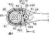
图6是图5中A-A剖面暨箭头方向所指的剖视图。Fig. 6 is A-A cross-section in Fig. 5 and the cross-sectional view indicated by the direction of the arrow.
图7是采用本实用新型的扳手的平面动作示意图。Fig. 7 is a schematic plan view of the action of the wrench of the present invention.
图8是图7中B-B剖面图。Fig. 8 is a B-B sectional view in Fig. 7 .
图9是采用本实用新型的扳手的平面动作示意图。Fig. 9 is a schematic plan view of the action of the wrench of the present invention.
图10是图9中C-C剖面图。Fig. 10 is a sectional view of C-C in Fig. 9 .
请参阅图3至图6,采用本实用新型的一种棘轮扳手,主要包含:Please refer to Fig. 3 to Fig. 6, a kind of ratchet wrench adopting the utility model mainly includes:
一工具柄20,该工具柄20的一端系为工作端21,另一端为握持端22;该工作端21内设有一开放口朝下的容室23,该容室23穿过其顶面槽壁各设有一棘轮口231、二螺丝孔位232、一轴杆孔位233;该容室23相邻该轴杆孔位233的侧槽壁设一半弧状的定位槽24,该定位槽24的开口系呈收口状;A
一棘轮30,设于该容室23具有棘轮口231的端部内,该棘轮30的中央连设一驱动杆31,该驱动杆31设一活动式嵌制元件311,供稳定套合于工件或结合其他套件;该嵌制元件311并由一穿伸出驱动杆30及棘轮口231的按钮32所控制;A
一调拨块40,系由一圆弧块状的根部41及一径向外扩张的齿块42所构成;该调拨块两侧位置各设一内凹的限位槽部43;该根部41设于工具柄20的定位槽24中,两侧的限位槽部43供该定位槽24收口状的侧壁端嵌入,使该调拨块40被定位于该定位槽24中,且无虞往棘轮30方向脱动;该齿块42相对该调拨块40系位一弧凹状的端面,其两端各设有由数个棘齿构成的棘齿面421,可分别与棘轮30啮合;该调拨块40的根部41中央设一多角槽孔45;A transfer block 40 is composed of an arc-shaped block-
一拨动结构50,具有一盘部51,该盘部51的一侧面设一轴杆52,该轴杆52的杆身上设一多角块53;该盘部51的另一侧面径向延伸一拨杆54;该盘部51设于该工作端21的壁面外,其轴杆52穿过该轴杆孔位233进入该调拨块40,其多角块53套入该多角槽孔45中,该轴杆52穿出该调拨块40,底端以一C型环55扣合,防止该拨动结构50由上方脱离;拨动该拨杆54,得以控制该调拨块40摆动,使其中一棘齿面421与棘轮30啮合;A toggle structure 50 has a
一封片60,设于该容室23的开放口处,并以二螺丝元件61穿过该螺丝孔位232将封片60锁合定位。A
一辅助定位结构,该调拨块40的齿块42设有二贯穿的孔422,该孔422中填设一组弹性定位元件,该弹性定位元件包含一弹簧423,该弹簧423的两端各设一定位珠424,该定位珠424端部设一定位杆425穿入该弹簧423中定位;该容室23壁面及该封片60对应二弹性定位元件邻侧的位置各设有一半球凹槽25、62,供该定位珠424的圆形端头嵌卡其中;An auxiliary positioning structure, the
请参阅图7至图10,操作使用本实用新型的活动扳手,系依预作用方向调动该拨杆54,该拨杆54带动该盘部51及该多角块53,因该多角块53与该调拨块40的多角槽孔45套合,故可带动该调拨块40向拨杆54拨动的方向拨转一角度,使该方向中的棘齿面421与该棘轮30的齿面相互啮合;此时,当活动扳手以该驱动杆31套住工件时,往作用方向带动,该调拨块40的棘齿面421卡制住该棘轮30,使扳手带动该棘轮30及工件往作用方向转以达松紧工件的目的,反之,当活动扳手往另一方向扳动时,该调拨块40的棘齿面421会被该棘轮30逆向推开,彼此棘齿相互推错,使活动扳手以不带动该棘轮30的方式空转复位。Please refer to Fig. 7 to Fig. 10, the operation and use of the adjustable wrench of the present utility model is to mobilize the driving
由于二半球凹槽25、62的位置系相对在二弹性定位元件之间,所以,当该调拨块40被该拨动结构50控制而往预定方向倾斜,并以其中一棘齿面421与该棘轮30啮合时,其中一弹性定位元件的定位珠424亦随着调拨块40的倾斜方向而移嵌至邻近的半球凹槽25、62中,而另一定位珠424则会移出半球凹槽25、62,藉此发挥辅助定位调拨块40的功能。而该弹性定位元件采弹簧423两端各抵顶一定位珠424的设计,一方面可消除调拨块40与容室23顶壁以及封片60的间隙,使设置更为稳定,当其中一棘齿面421与棘轮30咬合时,同侧位置的定位珠424卡合半球凹槽25、62中,增加咬合稳定性。Because the positions of the two
Claims (4)
Translated fromChinesePriority Applications (1)
| Application Number | Priority Date | Filing Date | Title |
|---|---|---|---|
| CN 01246107CN2485097Y (en) | 2001-06-22 | 2001-06-22 | Adjustment structure of ratchet wrench |
Applications Claiming Priority (1)
| Application Number | Priority Date | Filing Date | Title |
|---|---|---|---|
| CN 01246107CN2485097Y (en) | 2001-06-22 | 2001-06-22 | Adjustment structure of ratchet wrench |
Publications (1)
| Publication Number | Publication Date |
|---|---|
| CN2485097Ytrue CN2485097Y (en) | 2002-04-10 |
Family
ID=33657226
Family Applications (1)
| Application Number | Title | Priority Date | Filing Date |
|---|---|---|---|
| CN 01246107Expired - Fee RelatedCN2485097Y (en) | 2001-06-22 | 2001-06-22 | Adjustment structure of ratchet wrench |
Country Status (1)
| Country | Link |
|---|---|
| CN (1) | CN2485097Y (en) |
Cited By (2)
| Publication number | Priority date | Publication date | Assignee | Title |
|---|---|---|---|---|
| CN100363155C (en)* | 2002-11-06 | 2008-01-23 | 陈泰佐 | Adjustable spanner |
| CN100384593C (en)* | 2003-01-15 | 2008-04-30 | 伟立兴业股份有限公司 | Spanner with micro-angle brake clamping device |
- 2001
- 2001-06-22CNCN 01246107patent/CN2485097Y/ennot_activeExpired - Fee Related
Cited By (2)
| Publication number | Priority date | Publication date | Assignee | Title |
|---|---|---|---|---|
| CN100363155C (en)* | 2002-11-06 | 2008-01-23 | 陈泰佐 | Adjustable spanner |
| CN100384593C (en)* | 2003-01-15 | 2008-04-30 | 伟立兴业股份有限公司 | Spanner with micro-angle brake clamping device |
Similar Documents
| Publication | Publication Date | Title |
|---|---|---|
| AU2008201324B2 (en) | Dual pawl ratchet mechanism and reversing method | |
| US5957009A (en) | Control mechanism for ratchet wrench | |
| US6644148B2 (en) | Reversible ratchet-type wrench | |
| US6220123B1 (en) | Structure of a ratchet wrench | |
| US20030070512A1 (en) | Reversible ratchet-type wrench | |
| US6575060B1 (en) | Reversible ratchet wrench | |
| US6431030B1 (en) | Adjusting structure for a ratchet wrench | |
| US20040144218A1 (en) | Adjustable head for a wrench | |
| US20060117913A1 (en) | Selective one-way wrench | |
| TW202330200A (en) | Ratchet tool | |
| CN2485097Y (en) | Adjustment structure of ratchet wrench | |
| CN1151010C (en) | ratcheting tool | |
| CN2510240Y (en) | Lever touch dial silent wrench | |
| CN2068450U (en) | Reversible pipe wrench | |
| CN1131132C (en) | ratcheting tool | |
| CN1131131C (en) | A reversing block of a ratchet wrench and a ratchet wrench using the reversing block | |
| CN1121926C (en) | ratcheting tool | |
| CN2524892Y (en) | Steering mechanism for reversible ratchet wrench | |
| JP3148086U (en) | monkey wrench | |
| US20030221521A1 (en) | Ratchet tool having flat head | |
| CN2544898Y (en) | Reversible Ratchet Wrench | |
| CN2717623Y (en) | One-way wrench clamping structure | |
| GB2327058A (en) | Ratchet wrench | |
| CN2452684Y (en) | a ratchet screwdriver | |
| CN2468669Y (en) | hand tool drive head |
Legal Events
| Date | Code | Title | Description |
|---|---|---|---|
| C14 | Grant of patent or utility model | ||
| GR01 | Patent grant | ||
| C56 | Change in the name or address of the patentee | Owner name:LIANGYU CO., LTD. Free format text:FORMER NAME OR ADDRESS: GUO WENJIN; GUO WENQIN | |
| CP03 | Change of name, title or address | Address after:Floor 4, No. 63, Changchun Road, Dali County, Taichung County, Taiwan Province, China 1 Patentee after:Liang Yu Limited by Share Ltd Address before:Lane 320, Lane 41, Sha Tin Road, Tai Chi Township, Taichung County, Taiwan Patentee before:Guo Wenjin Patentee before:Guo Wenqin | |
| C19 | Lapse of patent right due to non-payment of the annual fee | ||
| CF01 | Termination of patent right due to non-payment of annual fee |