CN2476056Y - Heat Dissipation and Electromagnetic Wave Emission Prevention Device for Portable Computer - Google Patents
Heat Dissipation and Electromagnetic Wave Emission Prevention Device for Portable ComputerDownload PDFInfo
- Publication number
- CN2476056Y CN2476056YCN 01210263CN01210263UCN2476056YCN 2476056 YCN2476056 YCN 2476056YCN 01210263CN01210263CN 01210263CN 01210263 UCN01210263 UCN 01210263UCN 2476056 YCN2476056 YCN 2476056Y
- Authority
- CN
- China
- Prior art keywords
- side wall
- metal plate
- bottom case
- portable computer
- heat dissipation
- Prior art date
- Legal status (The legal status is an assumption and is not a legal conclusion. Google has not performed a legal analysis and makes no representation as to the accuracy of the status listed.)
- Expired - Fee Related
Links
- 230000017525heat dissipationEffects0.000titleclaimsabstractdescription11
- 230000002265preventionEffects0.000titleclaimsabstractdescription6
- 229910052751metalInorganic materials0.000claimsabstractdescription32
- 239000002184metalSubstances0.000claimsabstractdescription32
- 239000011888foilSubstances0.000claimsabstractdescription9
- 230000003287optical effectEffects0.000claimsdescription6
- 239000003973paintSubstances0.000claimsdescription6
- 239000004973liquid crystal related substanceSubstances0.000abstractdescription5
- 238000004519manufacturing processMethods0.000description4
- 239000011248coating agentSubstances0.000description3
- 238000000576coating methodMethods0.000description3
- 238000001816coolingMethods0.000description3
- 241000233805PhoenixSpecies0.000description2
- 238000000034methodMethods0.000description2
- RYGMFSIKBFXOCR-UHFFFAOYSA-NCopperChemical compound[Cu]RYGMFSIKBFXOCR-UHFFFAOYSA-N0.000description1
- 229910052782aluminiumInorganic materials0.000description1
- XAGFODPZIPBFFR-UHFFFAOYSA-NaluminiumChemical compound[Al]XAGFODPZIPBFFR-UHFFFAOYSA-N0.000description1
- 230000009286beneficial effectEffects0.000description1
- 210000000988bone and boneAnatomy0.000description1
- 210000004556brainAnatomy0.000description1
- 239000011889copper foilSubstances0.000description1
- 230000002950deficientEffects0.000description1
- 238000005516engineering processMethods0.000description1
- 230000006870functionEffects0.000description1
- PCHJSUWPFVWCPO-UHFFFAOYSA-NgoldChemical compound[Au]PCHJSUWPFVWCPO-UHFFFAOYSA-N0.000description1
- 238000007689inspectionMethods0.000description1
- 230000003902lesionEffects0.000description1
- 150000002739metalsChemical class0.000description1
- 230000000149penetrating effectEffects0.000description1
- 239000000126substanceSubstances0.000description1
- 210000001519tissueAnatomy0.000description1
Images


Landscapes
- Shielding Devices Or Components To Electric Or Magnetic Fields (AREA)
- Casings For Electric Apparatus (AREA)
Abstract
Translated fromChineseDescription
Translated fromChinese本实用新型涉及一种可携式电脑散热及防止电磁波释出装置。The utility model relates to a portable computer heat dissipation and electromagnetic wave release preventing device.
实用新型专利第99214382.9号揭示之“可携式电脑中央理器散热结构”(下称前案),主要是将配备有中央处理器、散热片与凤扇之主机板上下倒立安装在主机内,并与上方键盘(或触控式液晶萤幕)共同支持在一金属板上,如此凤扇将能因此邻接在主机壳预设之进气孔,使中央处理器不但能利用散热片与凤扇提高散热效率,且能不受主机上方键盘阻碍而直接抽取底壳外面空气,将中央处理器散发在散热片上之热量除去,而大幅提高电脑散热效率。The utility model patent No. 99214382.9 discloses the "Heat Dissipation Structure of Portable Computer Central Processor" (hereinafter referred to as the previous case), which mainly installs the main board equipped with the central processing unit, heat sink and fan upside down in the main machine. It is also supported on a metal plate together with the upper keyboard (or touch-sensitive LCD screen), so that the fan will be adjacent to the preset air intake hole in the main casing, so that the central processing unit can not only use the heat sink and the fan to improve Heat dissipation efficiency, and can directly extract the air outside the bottom case without being hindered by the keyboard on the top of the host, remove the heat dissipated by the CPU on the heat sink, and greatly improve the heat dissipation efficiency of the computer.
然而众所周知,任何一件产品,如果要大量生产,且能够达到零件之互换性,唯一的辨法便是先制造一种能生产某种特定零件之模具,这种模具只要配合生产该产品的特殊机器,就能在最短的时间内生产出大量且具互换性的各种零件产品了,如此不但减少人工成本,而且减少不良品的发生,也直接降低了产品之成本,更促进消费者购买的意愿。但是,对于少量需求而言,则其需求量不符合大量生产的成本效益;因为模具费非常昂贵。However, as we all know, if any product is to be mass-produced and the interchangeability of parts can be achieved, the only way to distinguish it is to first manufacture a mold that can produce a certain part. Special machines can produce a large number of interchangeable parts and components in the shortest time, which not only reduces labor costs, but also reduces the occurrence of defective products, which also directly reduces the cost of products and promotes consumers. willingness to buy. However, for small quantities, the quantity required is not cost-effective for mass production; because tooling is very expensive.
根据前案之设针,底壳上进气孔位置须在凤扇正下方,始能让凤扇顺利地抽取底壳外面空气以驱散热量。然而,一般中央处理器在主机板上位置并非固定不变,它可能随电脑制造商之系统设计而有所不同;相对的,进气孔在底壳上位置也要随之改变,如此势必要开发许多模具生产底壳。因此,若只是少量需求,则前案之设计显然不符成本效益。According to the design of the previous project, the position of the air intake hole on the bottom case must be directly below the fan, so that the fan can smoothly draw air from the outside of the bottom case to dissipate heat. However, the position of the general central processing unit on the motherboard is not fixed, and it may vary with the system design of the computer manufacturer; correspondingly, the position of the air intake hole on the bottom case will also change accordingly, so it is necessary Developed many molds to produce bottom shells. Therefore, if there is only a small amount of demand, the design of the previous proposal is obviously not cost-effective.
另一方面,虽然迄今科学家及学术界对于电脑使用时释出之电磁波是否真的会造成脑部或组织病变尚无定论,但却已引起消费大众疑虑。因此,许多国家都制定一套电磁波检验标准,电脑制造商也已开始研发减低电脑释放电磁波之技术,不过截至目前为止,成效并不显著。On the other hand, although scientists and academic circles have not yet concluded whether the electromagnetic waves released by computers will really cause brain or tissue lesions, it has aroused doubts among consumers. Therefore, many countries have formulated a set of electromagnetic wave inspection standards, and computer manufacturers have also begun to develop technologies to reduce the emission of electromagnetic waves from computers, but so far, the results have not been significant.
本实用新型的目的在于提供一种可携式电脑散热装置,该装置满足凤扇直接抽取主机底壳外面空气,供将中央处理器散热片上热量除去之功能下,允许中央处理器在主机板上位置任意更动,以节省制造有不同进气孔位置之底壳的模具费,以符合少量需求之成本效益。The purpose of this utility model is to provide a portable computer cooling device, which can directly extract the air outside the bottom shell of the host computer by the fan fan, and remove the heat from the heat sink of the central processing unit. The position can be changed arbitrarily, so as to save the mold cost of manufacturing bottom shells with different positions of air intake holes, so as to meet the cost-effectiveness of a small amount of demand.
本实用新型的另一目的在于提供一种防止电磁波释出之装置,该装置提供一有金属内表面之遮蔽空间,使电脑使用时释出之电磁波无法穿透该遮蔽空间,避免人体接触电磁波。Another object of the present invention is to provide a device for preventing the release of electromagnetic waves. The device provides a shielded space with a metal inner surface, so that the electromagnetic waves released when the computer is in use cannot penetrate the shielded space and prevent the human body from being exposed to electromagnetic waves.
本实用新型的可携式电脑散热及防止电磁波释出装置,主要由一上盖、金属板、键盘(或触控式液晶萤幕)、主机板及底壳组成,其特点是:底壳包含一开口,开口之大小,涵盖中央处理器在主机上的位置,底壳包含一有数个进气孔之壳盖,进气孔大部分被一固著在壳盖内表面之金属箔覆盖,仅留一面对主机板上中央处理器位置之窗孔,供凤扇直接抽取底壳外面空气将中央处理器散发在散热片上之热量除去。The portable computer heat dissipation and electromagnetic wave release prevention device of the present invention is mainly composed of a top cover, a metal plate, a keyboard (or a touch-sensitive liquid crystal screen), a main board and a bottom case, and its characteristic is that the bottom case includes a The opening, the size of the opening, covers the position of the central processing unit on the main unit. The bottom case includes a cover with several air intake holes. Most of the air intake holes are covered by a metal foil fixed on the inner surface of the cover, leaving only One side faces the window hole where the CPU is located on the main board, for the fan to directly draw the air outside the bottom case to remove the heat emitted by the CPU on the heat sink.
上述金属板周边向下弯折形成折边,底壳之内表面涂装导电漆,侧壁上端向外扩张形成搁架供折边搁在上面,使在底壳和金属板之间有一具有金属内表面之遮蔽空间,使电脑使用时释出之电磁波无法穿透该避蔽空间。The periphery of the above-mentioned metal plate is bent downward to form a hem, the inner surface of the bottom shell is coated with conductive paint, and the upper end of the side wall expands outward to form a shelf for the hem to rest on, so that there is a metal plate between the bottom shell and the metal plate. The sheltered space on the inner surface prevents the electromagnetic waves released by the computer from penetrating the sheltered space.
附图说明:Description of drawings:
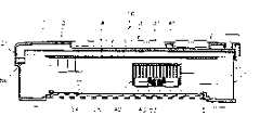
图1为本实用新型的可携式电脑横向剖面图。Fig. 1 is a transverse sectional view of a portable computer of the present invention.
图2为本实用新型的俯视立体分解图。Fig. 2 is a top perspective exploded view of the utility model.
图3为本实用新型的底壳分解图。Fig. 3 is an exploded view of the bottom case of the present invention.
图4为图1中A-A线的剖面图。Fig. 4 is a cross-sectional view of line A-A in Fig. 1 .
图5为图1中B-B线的剖面图。Fig. 5 is a sectional view of line B-B in Fig. 1 .
图中标号说明:Explanation of the labels in the figure:
1…上盖 2…金属板1…
3…键盘 4…主机板3...Keyboard 4...Motherboard
7…触控式液晶萤幕 5…底壳7...
8…光碟机 9…硬碟机8...CD-
10…可携式电脑 21…折边10...
25…遮蔽空间 31…按键25...
41…中央处理器 42…散热片41...
43…凤扇 51…开口43...Phoenix
52…壳盖 53…进气孔52...Shell
54…金属箔 55…窗孔54...Metal
56…搁架 57…第一侧壁56...Shelf 57...First side wall
58…第二侧壁 59…第三侧壁58...
60…第四侧壁 61…突沿60...the
62…翼片 66、63…螺孔62...Wings 66, 63...Screw holes
64…电路板 65…螺丝64
67内表面67 inner surface
68、69…容匣68, 69... container box
以下结合附图对本实用新型的结构、技术特征作进一步说明。Below in conjunction with accompanying drawing, structure, technical characterictic of the present utility model are described further.
如图1、2所示,本实用新型的可携式电脑10自上而下由一局部镂空的塑胶上盖1;一固定在上盖1下方的金属板2;一支持在金属板2上面的键盘3(或触控式液晶萤幕7,参阅图5所示),其按键31(或触控式液晶萤幕7)从上盖1的镂空处露出供操作;一上下倒立安装在金属板2下面之主机板4,主机板4上主要包含有中央处理器(CPU)41、记忆体(me mory)、输入/翰出埠(I/Oport)及计时装置(timer)等必要的电路及电元件,中央处理器41下面装有散热片42及凤扇43;以及一结合在上盖1下方之底壳5,底壳5与上盖1之内壁面有一装配室,以容纳主机板4、金属板2及键盘3(或触控式液晶萤幕7);另外,底壳5上装有光碟机8及硬碟机9。As shown in Figures 1 and 2, the
根据本实用新型的可携式电脑散热装置,其中底壳5有一开口51,开口51大小涵盖中央处理器41在主机板4上的位置,并被一利用螺丝(图未示出)锁紧在底壳5的壳盖52封闭,底壳5包含数个形式不拘之进气孔53,这些进气孔53大部分被一固著在壳盖52内表面的铝箔、铜箔或其它适当之金属箔54覆盖,仅切割出一面对中央处理器41之窗孔55,供凤扇43直接抽取底壳5外面空气,将中央处理器41散发在散热器42上之热量除去。如此,从系统设计需要致中央处理器41在主机板4上实际位置有所变动,也只要制造一种底壳5就能满足需求,解决现有技术须制造有不同进气孔位置之底壳的模具费,此设计对于少量需求极为有利。另外,因为壳盖52是可从底壳5上自由装卸,故非常方便中央处理器41、记忆体、光碟机8和硬碟机9的组装及排(导)线之连接与整理,同时有利于准系统(bare bone’即机壳十主机板)之销售。According to the portable computer cooling device of the present utility model, wherein the
需知,金属箔54的主要功用在于遮蔽中央处理器41正下方以外之进气孔53,防止因进气孔53涵盖范围太大,使排出的热空气又被凤扇43吸入而降低散热效率。It should be known that the main function of the
此外,由于进气孔53的关系,会增加在底壳5内表面涂装导电漆之难度,然因金属箔54本身即有导电性,故被金属箔54覆盖之进气孔53便毋需涂装导电漆,仅有未被金届箔54遮蔽之少部分进气孔53需要涂装,由于涂装面积大幅减少,因此容易许多。In addition, due to the relationship between the
再如图2所示,本实用新型另一重要部分是,金属板2周边进一步向下弯折成折边21,底壳5的内表面涂装导电漆(此乃可携式电脑或笔记型电脑在制造时,为了接地及导电需要之必要制程),侧壁上端向外扩张形成搁架56供折边21搁在上面(参阅图1、4所示),使在底壳5和金属板2之间有遮蔽空间25,由于遮蔽空间25之内表面这金属物质,兼以电磁波无法穿透金属,故能防止电脑使用时产生的电磁波释出主机外,避免人体接触电磁波,同时因金属板2具有导电性,故可省略在上盖1内表面涂装导电漆的制程及成本。底壳5上虽有进气孔53,但因电磁波为直线波,须进气孔53够大电磁波才能穿透,这些进气孔53之大小则控制在电磁波无法穿透之范围内。在附图的实施例中,为使主机板4上输入/输出埠露出底壳5外供连接输入/翰出设备之用,故底壳5后方除二端有侧壁外,大部分是缺口而无所谓的搁架;相对的,金属板2除后方折边21为”1”形,以直接搁在底壳5之内表面外,前方、左方及右方之折边21均为“L”形,而分别支持在底壳5对应边之”L”形搁架56上。As shown in Figure 2 again, another important part of the utility model is that the periphery of the
另外,如图3、5所示,为了方便光碟机8及硬碟机9之组装,在较佳的实施例中,底壳5的内表面67向上垂直延伸一第一侧壁57、第二侧壁58、第三侧壁59及第四侧壁60,其中第一一第三侧壁57-59相平行,顶边朝相邻侧壁之方向水平延伸若干突沿61,第四侧壁60和第二侧壁58垂直,并与第一侧壁57及其突沿61在底壳5上有一恰可接纳光碟机8的容匣68同时第四侧壁60二端向上延伸形成翼片62,每一翼片62上均有一螺孔63,供已穿过电路板64之螺丝65通过后旋入光碟机8(参阅图1所示),电路板64二面皆有一连接器(图未示出),其中一连接器可直接与光碟机8连接,另一连接器供连接排线之用,该排线另一端则连接至主机板4,使光碟机8可与主机板4达成电气连接。至于第二侧壁58、第三侧壁59及其突沿61则在底壳5上有一恰可容纳硬碟机9之容匣69,该容匣69四角落各有一螺孔66,供螺丝(图未示出·)从底壳5下方穿过后接旋入硬碟机9内,以将硬碟机9固定在底壳5上,其情况如第图5所示。In addition, as shown in Figures 3 and 5, in order to facilitate the assembly of the
当然,上述实施例可在不脱离本实用新型的范围下加以若干变化,故以上之说明所包含及附图中所示之全部事项应视为例示性而非限制性。Of course, some changes can be made to the above embodiments without departing from the scope of the present utility model, so all matters contained in the above description and shown in the drawings should be regarded as illustrative rather than restrictive.
Claims (3)
Translated fromChinesePriority Applications (1)
| Application Number | Priority Date | Filing Date | Title |
|---|---|---|---|
| CN 01210263CN2476056Y (en) | 2001-01-18 | 2001-01-18 | Heat Dissipation and Electromagnetic Wave Emission Prevention Device for Portable Computer |
Applications Claiming Priority (1)
| Application Number | Priority Date | Filing Date | Title |
|---|---|---|---|
| CN 01210263CN2476056Y (en) | 2001-01-18 | 2001-01-18 | Heat Dissipation and Electromagnetic Wave Emission Prevention Device for Portable Computer |
Publications (1)
| Publication Number | Publication Date |
|---|---|
| CN2476056Ytrue CN2476056Y (en) | 2002-02-06 |
Family
ID=33629846
Family Applications (1)
| Application Number | Title | Priority Date | Filing Date |
|---|---|---|---|
| CN 01210263Expired - Fee RelatedCN2476056Y (en) | 2001-01-18 | 2001-01-18 | Heat Dissipation and Electromagnetic Wave Emission Prevention Device for Portable Computer |
Country Status (1)
| Country | Link |
|---|---|
| CN (1) | CN2476056Y (en) |
Cited By (8)
| Publication number | Priority date | Publication date | Assignee | Title |
|---|---|---|---|---|
| CN100463594C (en)* | 2005-06-18 | 2009-02-18 | 鸿富锦精密工业(深圳)有限公司 | Electromagnetic shielding device with heat dissipation function |
| CN102789292A (en)* | 2012-07-09 | 2012-11-21 | 华为技术有限公司 | Peripheral component interconnection channel combination device and computer |
| CN103547126A (en)* | 2013-10-29 | 2014-01-29 | 黄肖峰 | Installer for processor |
| CN103547127A (en)* | 2013-10-29 | 2014-01-29 | 陈雪婵 | Installing device for processor |
| CN103547128A (en)* | 2013-10-29 | 2014-01-29 | 范全军 | Processor installation device capable of exhausting air in two directions |
| US9913400B2 (en) | 2013-06-07 | 2018-03-06 | Apple Inc. | Computer thermal system |
| CN110786083A (en)* | 2017-06-23 | 2020-02-11 | Meta系统股份公司 | Electronic power device for electric or hybrid vehicles and related implementation method |
| US11899509B2 (en) | 2013-06-07 | 2024-02-13 | Apple Inc. | Computer housing |
- 2001
- 2001-01-18CNCN 01210263patent/CN2476056Y/ennot_activeExpired - Fee Related
Cited By (25)
| Publication number | Priority date | Publication date | Assignee | Title |
|---|---|---|---|---|
| CN100463594C (en)* | 2005-06-18 | 2009-02-18 | 鸿富锦精密工业(深圳)有限公司 | Electromagnetic shielding device with heat dissipation function |
| CN102789292A (en)* | 2012-07-09 | 2012-11-21 | 华为技术有限公司 | Peripheral component interconnection channel combination device and computer |
| US10845852B2 (en) | 2013-06-07 | 2020-11-24 | Apple Inc. | Desktop electronic device |
| US9964999B2 (en) | 2013-06-07 | 2018-05-08 | Apple Inc. | Computer internal architecture |
| US12045099B2 (en) | 2013-06-07 | 2024-07-23 | Apple Inc. | Computer housing |
| US11899511B2 (en) | 2013-06-07 | 2024-02-13 | Apple Inc. | Computer housing |
| US11899509B2 (en) | 2013-06-07 | 2024-02-13 | Apple Inc. | Computer housing |
| US11256306B2 (en) | 2013-06-07 | 2022-02-22 | Apple Inc. | Computer housing |
| US9913400B2 (en) | 2013-06-07 | 2018-03-06 | Apple Inc. | Computer thermal system |
| US10254805B2 (en) | 2013-06-07 | 2019-04-09 | Apple Inc. | Desktop electronic device |
| US10248171B2 (en) | 2013-06-07 | 2019-04-02 | Apple Inc. | Desktop electronic device |
| US9974206B2 (en) | 2013-06-07 | 2018-05-15 | Apple Inc. | Computer internal architecture |
| US11256307B2 (en) | 2013-06-07 | 2022-02-22 | Apple Inc. | Desktop electronic device |
| US10073499B2 (en) | 2013-06-07 | 2018-09-11 | Apple Inc. | Computer internal architecture |
| US9946315B2 (en) | 2013-06-07 | 2018-04-17 | Apple Inc. | Desktop consumer electronic device |
| US10539984B2 (en) | 2013-06-07 | 2020-01-21 | Apple Inc. | Computer housing |
| US10725507B2 (en) | 2013-06-07 | 2020-07-28 | Apple Inc. | Desktop electronic device |
| CN103547126A (en)* | 2013-10-29 | 2014-01-29 | 黄肖峰 | Installer for processor |
| CN103547127A (en)* | 2013-10-29 | 2014-01-29 | 陈雪婵 | Installing device for processor |
| CN103547128B (en)* | 2013-10-29 | 2016-03-16 | 何慧敏 | A kind of processor erecting device that can two-wayly bleed |
| CN103547126B (en)* | 2013-10-29 | 2016-02-24 | 何慧敏 | A kind of erector for the treatment of device |
| CN103547127B (en)* | 2013-10-29 | 2016-02-24 | 何慧敏 | A kind of erecting device for the treatment of device |
| CN103547128A (en)* | 2013-10-29 | 2014-01-29 | 范全军 | Processor installation device capable of exhausting air in two directions |
| CN110786083A (en)* | 2017-06-23 | 2020-02-11 | Meta系统股份公司 | Electronic power device for electric or hybrid vehicles and related implementation method |
| CN110786083B (en)* | 2017-06-23 | 2023-10-03 | Meta系统股份公司 | Electronic power device for an electric or hybrid vehicle and associated implementation method |
Similar Documents
| Publication | Publication Date | Title |
|---|---|---|
| TWI310673B (en) | Electronic device, information processor, and electromagnetic radiation suppressing member | |
| EP0834795B1 (en) | Mechanical structure of information processing device | |
| US8711569B2 (en) | Server chassis | |
| JP5159052B2 (en) | Information processing device | |
| US8164900B2 (en) | Enclosure of electronic device | |
| US8351212B2 (en) | Mainframe structure | |
| CN2476056Y (en) | Heat Dissipation and Electromagnetic Wave Emission Prevention Device for Portable Computer | |
| TW201314425A (en) | Radiator device and electronic device using same | |
| US20030169567A1 (en) | Method and apparatus for removing heat from an electronic device | |
| CN205862284U (en) | A kind of PC cabinet being easy to heat radiation | |
| US9017023B2 (en) | Fan structure and electronic device applied with the same | |
| TWM261977U (en) | A modular dissipation assembling structure for PCB | |
| US8154865B2 (en) | Computer including a disk drive, motherboard and fan | |
| JP2003208238A (en) | Information processing equipment | |
| CN1093652C (en) | The mechanical structure of the information processing unit | |
| KR100313310B1 (en) | Portable computer with the dissipating apparatus of electronic system | |
| CN219266866U (en) | Electronic device and its frame structure | |
| CN1163807C (en) | power supply bracket | |
| CN213149662U (en) | Fan-free industrial personal computer | |
| CN216450001U (en) | High-efficient radiating mainboard structure of computer | |
| KR100371458B1 (en) | A computer system including a co-planar processor connector | |
| CN222994901U (en) | A compact computer case | |
| CN2359737Y (en) | Snap-on devices for central processing system components | |
| CN2710032Y (en) | The structure of the computer casing to prevent electromagnetic waves and improve internal heat dissipation | |
| CN2697710Y (en) | computer housing assembly |
Legal Events
| Date | Code | Title | Description |
|---|---|---|---|
| C14 | Grant of patent or utility model | ||
| GR01 | Patent grant | ||
| C19 | Lapse of patent right due to non-payment of the annual fee | ||
| CF01 | Termination of patent right due to non-payment of annual fee |