CN2194166Y - Dual Nail Guide for Engaging Broken Bone - Google Patents
Dual Nail Guide for Engaging Broken BoneDownload PDFInfo
- Publication number
- CN2194166Y CN2194166YCN 94211346CN94211346UCN2194166YCN 2194166 YCN2194166 YCN 2194166YCN 94211346CN94211346CN 94211346CN 94211346 UCN94211346 UCN 94211346UCN 2194166 YCN2194166 YCN 2194166Y
- Authority
- CN
- China
- Prior art keywords
- nail
- double
- locking intramedullary
- locking
- guide
- Prior art date
- Legal status (The legal status is an assumption and is not a legal conclusion. Google has not performed a legal analysis and makes no representation as to the accuracy of the status listed.)
- Expired - Fee Related
Links
- 208000010392Bone FracturesDiseases0.000titleclaimsdescription14
- 230000009977dual effectEffects0.000titleclaims3
- 210000000988bone and boneAnatomy0.000claimsabstractdescription37
- 229910000831SteelInorganic materials0.000claimsabstractdescription17
- 239000010959steelSubstances0.000claimsabstractdescription17
- 239000000523sampleSubstances0.000claimsdescription10
- 208000006670Multiple fracturesDiseases0.000claimsdescription6
- 238000003780insertionMethods0.000claimsdescription2
- 230000037431insertionEffects0.000claimsdescription2
- 230000002285radioactive effectEffects0.000abstract1
- 210000002303tibiaAnatomy0.000description10
- 210000000689upper legAnatomy0.000description10
- 206010017076FractureDiseases0.000description6
- 238000010586diagramMethods0.000description6
- 238000000034methodMethods0.000description5
- 230000035515penetrationEffects0.000description3
- 244000309466calfSpecies0.000description2
- 238000002594fluoroscopyMethods0.000description2
- 239000002184metalSubstances0.000description2
- 210000001185bone marrowAnatomy0.000description1
- 238000005553drillingMethods0.000description1
- 210000002758humerusAnatomy0.000description1
- 210000002414legAnatomy0.000description1
- 210000000236metacarpal boneAnatomy0.000description1
- 210000001872metatarsal boneAnatomy0.000description1
- 230000000399orthopedic effectEffects0.000description1
- 230000000149penetrating effectEffects0.000description1
- 230000005855radiationEffects0.000description1
- 210000002320radiusAnatomy0.000description1
- 230000000087stabilizing effectEffects0.000description1
- 230000008685targetingEffects0.000description1
- 210000000623ulnaAnatomy0.000description1
Images


Landscapes
- Surgical Instruments (AREA)
Abstract
Description
Translated fromChinese本实用新型涉及用于接合断骨的双钉导引装置。The utility model relates to a double-nail guiding device for joining broken bones.
已往的断骨接合治疗,常需借助X光透视,将断骨远端处螺丝置入固定,但既不方便,X光射线又会对人造成伤害。In the past, the joint treatment of broken bones often required the use of X-ray fluoroscopy to place screws at the distal end of the broken bone for fixation, but it was inconvenient and X-rays would cause harm to people.
想要在不借助X光透视的情况下把远端螺丝成功地置入胫骨或股骨锁定式骨髓内钉内,已成为业界需要解决的难题。如今远端螺孔的定位,最常用的一种技术是徒手法。然而,徒手法仍有费时以及需照射放射线的种种缺点。It has become a difficult problem to be solved in the industry to successfully place the distal screw into the tibial or femoral locking intramedullary nail without X-ray fluoroscopy. One of the most commonly used techniques for locating distal screw holes today is freehand. However, the manual technique still has the disadvantages of time-consuming and radiation exposure.
本实用新型的目的在于提供一种用于接合断骨的双钉导引装置。The purpose of the utility model is to provide a double nail guiding device for joining broken bones.
本实用新型的目的是这样实现的,即提供一种用于接合断骨的双钉导引装置,它包括一双钉导引架;一支从双钉导引架开始延伸的第一锁定式骨髓内钉,其中第一锁定式骨髓内钉沿其本身的一纵轴轴向界定出一槽道,同时这第一支骨钉包括一远端部,在该远端部至少界定出一孔口;一支从双钉导引架开始延伸的第二锁定式骨髓内钉,其中这第二锁定式骨髓内钉沿着本身的一纵轴轴向界定出一槽道,同时这第二支骨钉包括一远端部,在该远端部至少界定出一孔口;一根本身界定出一贯通槽道的中心或偏心导管,该导管用以穿过第一锁定式骨髓内钉并朝第二锁定式骨髓内钉的方向延伸;一根待插入导管上所界定的槽道内的钢线,该钢线用以延伸穿过导管,再穿过第二支骨钉上所界定的孔口;以及一根导引探针,该探针用以插入第二支骨钉上所界定的槽道并朝着这支骨钉的远端部延伸,其中当导引探针与钢线接触时,可确认第一骨钉的远端的孔口与第二骨钉远端部的孔口已彼此对齐。The purpose of this utility model is achieved by providing a double-nail guiding device for engaging broken bones, which includes a double-nail guiding frame; a first locking bone marrow extending from the double-nail guiding frame Inner nail, wherein the first interlocking intramedullary nail axially defines a channel along a longitudinal axis thereof, and the first bone nail includes a distal end portion defining at least one aperture at the distal end portion a second locking type intramedullary nail extending from the double nail guide frame, wherein the second locking type intramedullary nail axially defines a channel along a longitudinal axis thereof, and the second bone The nail includes a distal end portion defining at least one aperture; a central or eccentric conduit which itself defines a through channel for passing through the first locking intramedullary nail and toward the second The direction of the two locking intramedullary nails extends; a steel wire to be inserted into the channel defined on the catheter, the steel wire is used to extend through the catheter, and then pass through the hole defined on the second bone nail; and a guide stylet for inserting into the channel defined on the second bone screw and extending towards the distal end of the bone screw, wherein when the guide stylet comes into contact with the steel wire, It can be confirmed that the aperture at the distal end of the first bone screw and the aperture at the distal end of the second bone screw are aligned with each other.
本实用新型装置的优点在于第一锁定式骨髓内钉与第二锁定式骨髓内钉所制成的长度及尺寸均相等,可互相交换使用。以远端螺孔锁定为目标的程序因而简化,且成功率达100%。同时在进行股骨的远端螺孔锁定期间,病人和骨科医生不需受到放射线的照射。The advantage of the device of the utility model is that the first locking intramedullary nail and the second locking intramedullary nail are equal in length and size, and can be used interchangeably. The procedure targeting distal screw hole locking is thus simplified with a 100% success rate. At the same time, during the locking of the distal screw hole of the femur, the patient and the orthopedic surgeon do not need to be exposed to radiation.
以下结合附图,描述本实用新型的实施例,其中:Below in conjunction with accompanying drawing, describe embodiment of the present utility model, wherein:
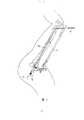
图1是本实用新型以胫骨锁定方式穿设骨髓内钉远端螺孔的双钉导引装置的透视图;Fig. 1 is the perspective view of the double nail guiding device of the utility model that penetrates the distal screw hole of the intramedullary nail in the tibial locking mode;
图2为示出双钉导引装置在胫骨中穿设最远端螺孔的操作示意图;Fig. 2 is a schematic diagram showing the operation of the double nail guiding device passing through the most distal screw hole in the tibia;
图3为双钉导引装置下钻子钻入胫骨中最远端螺孔中的操作示意图;3 is a schematic diagram of the operation of drilling the drill into the most distal screw hole in the tibia under the double nail guiding device;
图4为示出双钉导引装置下螺丝旋入胫骨中最远端螺孔中的示意图;4 is a schematic diagram showing that the screw under the double nail guiding device is screwed into the most distal screw hole in the tibia;
图5为本实用新型以股骨锁定方式穿设骨髓内钉的远端螺孔的双钉导引装置的分解图;Fig. 5 is an exploded view of the double-nail guiding device of the present invention that penetrates the distal screw hole of the intramedullary nail in a femoral locking manner;
图6为示出双钉导引装置在股骨中穿设最远端螺孔的操作示意图;6 is a schematic diagram showing the operation of the double nail guiding device to penetrate the most distal screw hole in the femur;
图7为使用双钉导引装置,钻子钻入股骨中最远端螺孔中的操作示意图;7 is a schematic diagram of the operation of the drill drilled into the most distal screw hole in the femur using the double nail guiding device;
图8为示出双钉导引装置将螺丝旋入股骨中最远端螺孔中的示意图。FIG. 8 is a schematic diagram showing a double screw guide screwing a screw into the most distal screw hole in a femur.
本实用新型用于稳定断骨的双钉导引装置,包括一个双钉导引架,以及从这双钉导引架开始延伸的第一与第二锁定式骨髓内钉一即插入骨中的骨钉,其中各锁定式骨髓内钉均沿其本身纵轴轴向界定出一槽道。同时锁定式骨髓内钉各设一远端部,而在这远端部上至少有一孔口。一根本身中心设有一槽道的中心或偏心导管会穿过第一锁定式骨髓内钉并朝第二锁定式骨髓内钉的方向延伸。另有柯氏钢线可插入导管的槽道内,钢线在延伸穿过导管后,即会再穿过置于待固定的骨头内的第二锁定式骨髓内钉所界定的孔口。还有导引探针可供插入第二锁定式骨髓内钉上所界定的槽道并朝这支骨钉的远端部延伸。当导引探针与钢线接触时,可确认第一锁定式骨髓内钉远端部的孔口与第二锁定式骨髓内远端部的孔口已彼此对齐。The utility model is used for stabilizing a broken bone with a double-nail guiding device, which comprises a double-nail guiding frame, and first and second locking intramedullary nails extending from the double-nail guiding frame—that is, inserted into the bone. A bone nail, wherein each locking intramedullary nail axially defines a groove along its own longitudinal axis. At the same time, each of the locking intramedullary nails is provided with a distal end, and there is at least one opening on the distal end. A central or eccentric catheter with a channel in its center passes through the first locking intramedullary nail and extends towards the second locking intramedullary nail. Another Coriolis steel wire can be inserted into the groove of the catheter. After the steel wire is extended through the catheter, it will pass through the opening defined by the second locking intramedullary nail placed in the bone to be fixed. There is also a guide stylet for insertion into the channel defined on the second locking intramedullary nail and extending toward the distal end of the nail. When the guiding probe is in contact with the steel wire, it can be confirmed that the aperture of the distal end of the first locking intramedullary nail and the aperture of the distal end of the second locking intramedullary nail are aligned with each other.
参阅附图,尤其是图1,表示出本实用新型双钉导引装置,该装置设有一胫骨双钉导引架1,导引架可和两根导螺杆2连接两支一样长度的骨钉3、4。将被打入折断胫骨内的那根骨钉称为“真钉”。另一根位在小腿内缘的骨钉则根据其导引用途而称“导钉”。例如,在右胫骨发生不稳定骨折的情况下,组合的左侧骨钉3即为将被插入折断胫骨内的真钉。位在小腿内侧的右侧骨钉4则当作导钉。或者,在左胫骨发生不稳定骨折的情况下,即用右侧骨钉4当作真钉,并用左侧骨钉3当作导钉。Referring to accompanying drawings, especially Fig. 1, show the utility model double-nail guiding device, this device is provided with a tibial double-nail guiding
如图2所示,在使用本实用新型双钉导引装置时,以一根柯氏钢线5和一支偏心导管6来定出胫骨内真钉3最远端螺孔的位置。然而,由于胫骨锁定式骨髓内钉的远端螺孔可能在制造时发生误差,因此需设计若干套正中心和偏心导管以供矫正这些固有的误差。As shown in Figure 2, when using the utility model double nail guiding device, a Coriolis
另外,会将一支导引探针7从真钉3的近端插入到远端,以确定钢线5能贯穿真钉3的最远端螺孔。当导引探针7接触到柯氏钢线5时,会听到金属撞击声。完成贯穿后,即把钢线5和导管6取出。In addition, a
图3示出一支从前述柯氏钢线5预先钻穿皮层穿过的钻子8。此时可再度使用导引探针7,来确定钻子8确实贯穿真钉3。完成贯穿后,即可把钻子8和导钉4取出。FIG. 3 shows a
图4示出将一螺丝9旋入真钉3之内的情形。此时可用导引探钉7,确定将螺丝9旋入的适当位置。根本不需用经放射线的照射。FIG. 4 shows the situation in which a
重复如前所述的相同程序,即可达到胫骨锁定式骨髓内钉第二远端联锁螺孔的位置。Repeat the same procedure as previously described to reach the position of the second distal interlocking screw hole of the tibial locking intramedullary nail.
图5示出本实用新型股骨双钉导引架10的分解图。双钉导引架10,可和两根导螺杆2连接两支一样长度的骨钉11、12。将被打入折断胫骨之内的那根骨钉称为“真钉”。另一根位在大腿侧缘的骨钉则根据其导引的用途而称为“导钉”。例如,在右股骨发生不稳定骨折的情况下,组合的左侧骨钉11即为将被插入折断股骨之内的真钉。反之,位在腿部外侧边的右侧骨钉12则当作导钉。若在左股骨发生不稳定骨折的情况下,仍然用左侧骨钉11当作真钉,并用右侧骨钉12当作导钉。由于股骨锁定式骨髓内钉的远端螺孔可能在制造时发生误差,因此需设计若干套偏心管以供矫正这些固有的误差。Fig. 5 shows an exploded view of the
如图6所示,在使用本实用新型双钉导引装置时,以一根柯氏钢线5和一支偏心导管6来定出股骨内真钉11最远端螺孔的位置。另外,会将一支导引探针7从真钉11的近端插入到远端,以确定钢线5能贯穿真钉11的最远端螺孔。当导引探针7接触到钢线5时,会听到金属撞击声。等完成贯穿后,即把钢线5和导管6取出。As shown in Fig. 6, when using the double-nail guiding device of the present invention, a Coriolis
图7示出一支从前述柯氏钢线5预先钻穿皮层的钻子8。此时可再度使用导引探针7,来确定钻子8确实能贯穿真钉11。完成贯穿后,即可把钻子8和导钉12取出。FIG. 7 shows a
图8示出将一螺丝9旋入真钉11内的情形。此时可用导引探针7,确保能将螺丝9旋入适当位置。根本不需放射线的照射。FIG. 8 shows the situation in which a
重复如前所述的相同程序,即可定出股骨锁定式骨髓内钉第二远端螺孔的位置。Repeat the same procedure as previously described to determine the position of the second distal screw hole of the femoral locking intramedullary nail.
但应注意的是,本实用新型装置可适用于各种不同形式锁定式骨髓内钉远端螺孔的锁定。However, it should be noted that the device of the present invention is suitable for locking the distal screw holes of various locking intramedullary nails.
凡是长骨的骨折,例如胫骨、股骨、肱骨、桡骨、尺骨、掌骨和蹠骨的骨折等,均可使用本实用新型双钉导引装置来锁定。All fractures of long bones, such as fractures of tibia, femur, humerus, radius, ulna, metacarpal and metatarsal bones, etc., can be locked using the double nail guiding device of the present invention.
Claims (11)
Translated fromChinesePriority Applications (1)
| Application Number | Priority Date | Filing Date | Title |
|---|---|---|---|
| CN 94211346CN2194166Y (en) | 1994-05-10 | 1994-05-10 | Dual Nail Guide for Engaging Broken Bone |
Applications Claiming Priority (1)
| Application Number | Priority Date | Filing Date | Title |
|---|---|---|---|
| CN 94211346CN2194166Y (en) | 1994-05-10 | 1994-05-10 | Dual Nail Guide for Engaging Broken Bone |
Publications (1)
| Publication Number | Publication Date |
|---|---|
| CN2194166Ytrue CN2194166Y (en) | 1995-04-12 |
Family
ID=33828497
Family Applications (1)
| Application Number | Title | Priority Date | Filing Date |
|---|---|---|---|
| CN 94211346Expired - Fee RelatedCN2194166Y (en) | 1994-05-10 | 1994-05-10 | Dual Nail Guide for Engaging Broken Bone |
Country Status (1)
| Country | Link |
|---|---|
| CN (1) | CN2194166Y (en) |
- 1994
- 1994-05-10CNCN 94211346patent/CN2194166Y/ennot_activeExpired - Fee Related
Similar Documents
| Publication | Publication Date | Title |
|---|---|---|
| US5374271A (en) | Double nail guiding system for targeting of distal screw holes of interlocking nails | |
| US7785326B2 (en) | System for intramedullary rod fixation and method therefor | |
| US20030135211A1 (en) | Intramedullary nail, device for inserting a screw into the same and method thereof | |
| US3990438A (en) | Bone fracture fixation and compression apparatus | |
| US4913137A (en) | Intramedullary rod system | |
| EP0059044B1 (en) | Tool for use in inserting a surgical wire | |
| EP0371910B1 (en) | Intramedullary nail | |
| US9192416B2 (en) | Intramedullary rod with spiraling flutes | |
| US3118444A (en) | Forearm rod for fractures | |
| KR20080055844A (en) | Orthopedic Implant Insertion Handles and Aiming Guides | |
| US10470782B2 (en) | Guidance system and method for bone fusion | |
| WO2005044083A2 (en) | Intramedullary nail-based bone fracture treatment | |
| AU2014324172A1 (en) | Guidance system and method for bone fusion | |
| JP2004527276A (en) | Bone fixation devices and jigs | |
| US5152766A (en) | Femoral wire guide instrument | |
| US11344341B2 (en) | Intramedullary fixation nail and method of use | |
| US20250195085A1 (en) | Reamer device with integrated depth gauging | |
| RU2289351C2 (en) | Intramedullary pin for performing trochanteric femur fracture osteosynthesis | |
| US10952780B1 (en) | Method of reducing a fracture of the lateral malleolus | |
| CN2194166Y (en) | Dual Nail Guide for Engaging Broken Bone | |
| CN216570181U (en) | A universal guide for minimally invasive surgery of femoral neck fractures | |
| CN1111500A (en) | Dual Nail Guide for Engaging Broken Bone | |
| CN116133605A (en) | Funnel Hole for Intramedullary Nails | |
| JP3342999B2 (en) | Lag screw insertion direction determination device for intramedullary nail | |
| JP2000116668A (en) | Intramedullary nail |
Legal Events
| Date | Code | Title | Description |
|---|---|---|---|
| C14 | Grant of patent or utility model | ||
| GR01 | Patent grant | ||
| C19 | Lapse of patent right due to non-payment of the annual fee | ||
| CF01 | Termination of patent right due to non-payment of annual fee |