CN219343760U - A reinforced I-beam - Google Patents
A reinforced I-beamDownload PDFInfo
- Publication number
- CN219343760U CN219343760UCN202320650633.1UCN202320650633UCN219343760UCN 219343760 UCN219343760 UCN 219343760UCN 202320650633 UCN202320650633 UCN 202320650633UCN 219343760 UCN219343760 UCN 219343760U
- Authority
- CN
- China
- Prior art keywords
- horizontal
- steel
- plate
- vertical
- plates
- Prior art date
- Legal status (The legal status is an assumption and is not a legal conclusion. Google has not performed a legal analysis and makes no representation as to the accuracy of the status listed.)
- Expired - Fee Related
Links
Images


Classifications
- Y—GENERAL TAGGING OF NEW TECHNOLOGICAL DEVELOPMENTS; GENERAL TAGGING OF CROSS-SECTIONAL TECHNOLOGIES SPANNING OVER SEVERAL SECTIONS OF THE IPC; TECHNICAL SUBJECTS COVERED BY FORMER USPC CROSS-REFERENCE ART COLLECTIONS [XRACs] AND DIGESTS
- Y02—TECHNOLOGIES OR APPLICATIONS FOR MITIGATION OR ADAPTATION AGAINST CLIMATE CHANGE
- Y02E—REDUCTION OF GREENHOUSE GAS [GHG] EMISSIONS, RELATED TO ENERGY GENERATION, TRANSMISSION OR DISTRIBUTION
- Y02E10/00—Energy generation through renewable energy sources
- Y02E10/50—Photovoltaic [PV] energy
Landscapes
- Joining Of Building Structures In Genera (AREA)
Abstract
Description
Translated fromChinese技术领域technical field
本实用新型涉及钢材件技术领域,具体地说,涉及一种加强型工字钢件。The utility model relates to the technical field of steel parts, in particular to a reinforced I-shaped steel part.
背景技术Background technique
工字钢件指的是截面形状呈工字形的钢材结构,工字钢件广泛应用于建筑材料,起到对建筑进行稳定支撑的效果,工字钢件一般采用含碳钢材料制成,其表面的粗糙度可以根据实际需要进行精度加工操作。I-shaped steel parts refer to steel structures with an I-shaped cross-section. I-shaped steel parts are widely used in building materials to provide stable support for buildings. I-shaped steel parts are generally made of carbon-containing steel materials. The roughness of the surface can be processed according to actual needs.
常规的工字钢件在使用时,一般是直接由两个竖直板体和设置在两个竖直板体之间的水平板体组成,其两侧板体与中间板体之间的固定接触面积较小,且两侧板体之间缺少对应的抗压支撑组件,在受压后,容易发生变形,不具有加强稳定性能的优点,不利于延长使用寿命。鉴于此,我们提出了一种加强型工字钢件。When the conventional I-shaped steel parts are used, they are generally directly composed of two vertical plates and a horizontal plate arranged between the two vertical plates. The contact area is small, and there is a lack of corresponding anti-compression support components between the two sides of the board. After being compressed, it is easy to deform, does not have the advantage of enhancing stability, and is not conducive to prolonging the service life. In view of this, we propose a reinforced I-beam.
实用新型内容Utility model content
本实用新型的目的在于提供一种加强型工字钢件,以解决上述背景技术中提出的缺陷。The purpose of this utility model is to provide a reinforced I-shaped steel part to solve the above-mentioned defects in the background technology.
为实现上述目的,本实用新型提供如下技术方案:In order to achieve the above object, the utility model provides the following technical solutions:
一种加强型工字钢件,包括工字支撑钢材,所述工字支撑钢材由呈水平状设置的水平钢板和两个相互对称且分别设置在所述水平钢板两侧边位置处的竖直钢板组成,所述水平钢板的顶面和底面上均设置有水平加厚板,所述水平加厚板与所述竖直钢板的拐角部位处固定安装有拐角支撑钢板,所述拐角支撑钢板用于对竖直钢板进行支撑;两个所述竖直钢板之间设置有多个等间距排列的侧边板支撑组件,所述侧边板支撑组件包括与两个所述竖直钢板之间可拆卸连接的水平板,所述水平板用于对竖直钢板进行支撑。A reinforced I-shaped steel part, including I-shaped supporting steel, said I-shaped supporting steel consists of a horizontal steel plate arranged horizontally and two vertical steel plates that are symmetrical to each other and respectively arranged at the two sides of the horizontal steel plate. Composed of steel plates, horizontal thickened plates are arranged on the top and bottom surfaces of the horizontal steel plates, and corner supporting steel plates are fixedly installed at the corners of the horizontal thickened plates and the vertical steel plates, and the corner supporting steel plates are used for For supporting the vertical steel plates; a plurality of side plate support assemblies arranged at equal intervals are arranged between the two vertical steel plates, and the side plate support assemblies include Disassemble the connected horizontal plate, which is used to support the vertical steel plate.
优选的,所述拐角支撑钢板与所述水平钢板和竖直钢板之间设置有通孔,所述通孔用于减轻重量。Preferably, through holes are provided between the corner support steel plates and the horizontal and vertical steel plates, and the through holes are used to reduce weight.
优选的,所述竖直钢板内设置有多个与外界相连通的卡槽,所述水平板的端部固定安装有卡块,所述卡块位于所述卡槽内并与所述卡槽之间卡接配合,便于对水平板进行固定安装和拆卸操作,方便根据需要进行安装。Preferably, the vertical steel plate is provided with a plurality of slots communicating with the outside world, and the end of the horizontal plate is fixedly equipped with a block, and the block is located in the slot and connected to the slot. The clamping fit between them is convenient for the fixed installation and disassembly of the horizontal plate, and it is convenient for installation according to the needs.
优选的,所述卡块的尺寸与所述卡槽的尺寸相适配,所述卡块与所述卡槽的截面均呈T字形,使卡块不易出现从卡槽内脱离的情况。Preferably, the size of the clamping block matches the size of the clamping slot, and the cross-sections of the clamping block and the clamping slot are T-shaped, which makes it difficult for the clamping block to fall out of the clamping slot.
优选的,所述水平钢板、所述竖直钢板、所述拐角支撑钢板和所述水平加厚板为一体成型结构,保证整体的结构更加牢固稳定。Preferably, the horizontal steel plate, the vertical steel plate, the corner support steel plate and the horizontal thickened plate are integrally formed to ensure a firmer and more stable overall structure.
优选的,所述水平板的两端部均固定安装在抵在所述竖直钢板内表面上的抵接板,便于利用抵接板抵紧在竖直钢板上,起到稳定支撑的效果。Preferably, both ends of the horizontal plate are fixedly mounted on the abutment plate abutting against the inner surface of the vertical steel plate, so that the abutment plate can be used to abut against the vertical steel plate to provide stable support.
优选的,所述水平板的底面中心位置处固定安装有竖直抗压板,所述竖直抗压板的底端固定安装有抵在所述水平加厚板上的抵紧板,便于利用竖直抗压板起到对水平板进行进一步稳定支撑的效果。Preferably, a vertical anti-pressure plate is fixedly installed at the center of the bottom surface of the horizontal plate, and the bottom end of the vertical anti-pressure plate is fixedly installed with a pressing plate against the horizontal thickened plate, which is convenient for use The vertical anti-compression plate plays the role of further stabilizing the support of the horizontal plate.
与现有技术相比,本实用新型的有益效果是:Compared with the prior art, the beneficial effects of the utility model are:
1、本实用新型通过设置的水平加厚板,能够使水平钢板的厚度增加,提高抗压性能,另外通过设置的拐角支撑钢板,实现对竖直钢板进行进一步的支撑,且能够增大竖直钢板与水平加厚板和水平钢板之间的固定接触面积,同时,拐角支撑钢板能够对竖直钢板进行支撑,起到稳定支撑的效果,使整体的结构更加牢固稳定,不易受压变形,解决了常规的工字钢件在使用时,其两侧板体与中间板体之间的固定接触面积较小,且两侧板体之间缺少对应的抗压支撑组件,在受压后,容易发生变形,不具有加强稳定性能的优点,不利于延长使用寿命的问题。1. The utility model can increase the thickness of the horizontal steel plate and improve the compressive performance through the set horizontal thickened plate. In addition, the set corner supports the steel plate to realize further support for the vertical steel plate, and can increase the vertical The fixed contact area between the steel plate and the horizontal thickened plate and the horizontal steel plate. At the same time, the corner support steel plate can support the vertical steel plate, which has the effect of stabilizing the support, making the overall structure more firm and stable, and less prone to compression deformation. When conventional I-shaped steel parts are used, the fixed contact area between the two side plates and the middle plate is small, and there is a lack of corresponding compression support components between the two side plates. After compression, it is easy to Deformation does not have the advantage of enhancing stability, which is not conducive to prolonging the service life.
2、本实用新型通过设置的侧边板支撑组件,保证在使用时,能够利用水平板和竖直抗压板实现对竖直钢板和水平钢板进行进一步的稳定支撑,起到稳定支撑的效果。2. The utility model ensures that the horizontal plate and the vertical anti-compression plate can be used to further stably support the vertical steel plate and the horizontal steel plate during use by setting the side plate support assembly, thereby achieving the effect of stable support.
附图说明Description of drawings
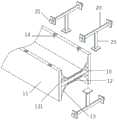
图1为本实用新型的整体结构示意图;Fig. 1 is the overall structural representation of the utility model;
图2为本实用新型的爆炸结构示意图;Fig. 2 is a schematic diagram of the explosion structure of the utility model;
图3为本实用新型侧边板支撑组件的结构示意图。Fig. 3 is a structural schematic diagram of the side panel support assembly of the present invention.
图中各个标号的意义为:The meaning of each label in the figure is:
1、工字支撑钢材;10、水平钢板;11、竖直钢板;12、水平加厚板;13、拐角支撑钢板;131、通孔;14、卡槽;1. I-shaped support steel; 10. Horizontal steel plate; 11. Vertical steel plate; 12. Horizontal thickened plate; 13. Corner support steel plate; 131. Through hole; 14. Card slot;
2、侧边板支撑组件;20、水平板;21、卡块;22、抵接板;23、竖直抗压板;24、抵紧板。2. Side plate support assembly; 20. Horizontal plate; 21. Block; 22. Abutment plate; 23. Vertical compression plate; 24. Clamping plate.
具体实施方式Detailed ways
下面将结合本实用新型实施例中的附图,对本实用新型实施例中的技术方案进行清楚、完整的描述,显然,所描述的实施例仅仅是本实用新型一部分实施例,而不是全部的实施例。基于本实用新型中的实施例,本领域普通技术人员在没有做出创造性劳动前提下所获得的所有其他实施例,都属于本实用新型保护的范围。The technical solutions in the embodiments of the present invention will be clearly and completely described below in conjunction with the accompanying drawings in the embodiments of the present invention. Obviously, the described embodiments are only part of the embodiments of the present invention, not all of them. example. Based on the embodiments of the present utility model, all other embodiments obtained by persons of ordinary skill in the art without making creative efforts belong to the scope of protection of the present utility model.
请参阅图1-图3,本实用新型提供一种技术方案:一种加强型工字钢件,包括工字支撑钢材1,工字支撑钢材1由呈水平状设置的水平钢板10和两个相互对称且分别设置在水平钢板10两侧边位置处的竖直钢板11组成,水平钢板10的顶面和底面上均设置有水平加厚板12,水平加厚板12用于增加水平钢板10的厚度,提高抗压性;Please refer to Fig. 1-Fig. 3, the utility model provides a kind of technical scheme: a kind of reinforced I-shaped steel part, comprises I-shaped supporting steel material 1, and I-shaped supporting steel material 1 is made up of the
具体地,水平加厚板12与竖直钢板11的拐角部位处固定安装有拐角支撑钢板13,拐角支撑钢板13用于对竖直钢板11进行支撑,水平钢板10、竖直钢板11、拐角支撑钢板13和水平加厚板12为一体成型结构,保证整体的结构更加牢固稳定;Specifically, a corner
具体地,两个竖直钢板11之间设置有多个等间距排列的侧边板支撑组件2,侧边板支撑组件2包括与两个竖直钢板11之间可拆卸连接的水平板20,水平板20用于对竖直钢板11进行支撑,使竖直钢板11受压后不易变形,提高竖直钢板11的抗压性能。Specifically, a plurality of side
本实施例中,拐角支撑钢板13与水平钢板10和竖直钢板11之间设置有通孔131,通孔131用于减轻重量,使运输过程中更加顺利。In this embodiment, a
进一步地,竖直钢板11内设置有多个与外界相连通的卡槽14,水平板20的端部固定安装有卡块21,卡块21位于卡槽14内并与卡槽14之间卡接配合,便于对水平板20进行固定安装和拆卸操作,方便根据需要进行安装。Further, the
此外,卡块21的尺寸与卡槽14的尺寸相适配,卡块21与卡槽14的截面均呈T字形,使卡块21不易出现从卡槽14内脱离的情况。In addition, the size of the clamping
值得说明的是,水平板20的两端部均固定安装在抵在竖直钢板11内表面上的抵接板22,便于利用抵接板22抵紧在竖直钢板11上,起到稳定支撑的效果。It is worth noting that both ends of the
值得注意的是,水平板20的底面中心位置处固定安装有竖直抗压板23,竖直抗压板23的底端固定安装有抵在水平加厚板12上的抵紧板24,便于利用竖直抗压板23起到对水平板20进行进一步稳定支撑的效果。It is worth noting that a
本实用新型的加强型工字钢件在使用时,水平加厚板12增加了厚度,能够使水平钢板10不易受压损坏,另外,拐角支撑钢板13对水平加厚板12、竖直钢板11和水平钢板10之间进行支撑,进一步抗压保护,最后,根据需要,将卡块21卡入到卡槽14内,同时,使抵紧板24抵在水平加厚板12上,抵接板22抵在竖直钢板11的内表面上,进一步进行抗压支撑,提高装置的强度,方便使用。When the reinforced I-shaped steel part of the utility model is in use, the thickness of the horizontal thickened
以上显示和描述了本实用新型的基本原理、主要特征和本实用新型的优点。本行业的技术人员应该了解,本实用新型不受上述实施例的限制,上述实施例和说明书中描述的仅为本实用新型的优选例,并不用来限制本实用新型,在不脱离本实用新型精神和范围的前提下,本实用新型还会有各种变化和改进,这些变化和改进都落入要求保护的本实用新型范围内。本实用新型要求保护范围由所附的权利要求书及其等效物界定。The basic principles, main features and advantages of the present utility model have been shown and described above. Those skilled in the industry should understand that the utility model is not limited by the above-mentioned embodiments. The above-mentioned embodiments and descriptions are only preferred examples of the utility model, and are not used to limit the utility model. Without departing from the utility model Under the premise of the spirit and scope, the utility model also has various changes and improvements, and these changes and improvements all fall within the scope of the claimed utility model. The scope of protection required by the utility model is defined by the appended claims and their equivalents.
Claims (7)
Priority Applications (1)
| Application Number | Priority Date | Filing Date | Title |
|---|---|---|---|
| CN202320650633.1UCN219343760U (en) | 2023-03-28 | 2023-03-28 | A reinforced I-beam |
Applications Claiming Priority (1)
| Application Number | Priority Date | Filing Date | Title |
|---|---|---|---|
| CN202320650633.1UCN219343760U (en) | 2023-03-28 | 2023-03-28 | A reinforced I-beam |
Publications (1)
| Publication Number | Publication Date |
|---|---|
| CN219343760Utrue CN219343760U (en) | 2023-07-14 |
Family
ID=87111311
Family Applications (1)
| Application Number | Title | Priority Date | Filing Date |
|---|---|---|---|
| CN202320650633.1UExpired - Fee RelatedCN219343760U (en) | 2023-03-28 | 2023-03-28 | A reinforced I-beam |
Country Status (1)
| Country | Link |
|---|---|
| CN (1) | CN219343760U (en) |
- 2023
- 2023-03-28CNCN202320650633.1Upatent/CN219343760U/ennot_activeExpired - Fee Related
Similar Documents
| Publication | Publication Date | Title |
|---|---|---|
| CN219343760U (en) | A reinforced I-beam | |
| CN218587105U (en) | Briquetting, installation mechanism and photovoltaic system | |
| CN213647971U (en) | Longitudinal formwork for producing light wall material | |
| CN212641870U (en) | A unitary assembled large travertine curtain wall pendant system | |
| CN209956099U (en) | A high-strength and modularly designed composite material carriage floor | |
| CN114351902A (en) | A prefabricated partition wall fixed with M-type aggregate and M-type shrapnel | |
| CN214461645U (en) | Novel pin-connected panel opening building carrier plate | |
| CN209227879U (en) | A kind of novel finished product glass-fiber-plate and keel | |
| CN113062545A (en) | A slit-type inner corner structure | |
| CN221546082U (en) | Manual board with high supporting strength | |
| CN216215224U (en) | A kind of weak current engineering equipment installation frame | |
| CN220336315U (en) | Stone pendant with strengthening rib | |
| CN221298428U (en) | X-shaped metal composite tile and novel BIPV photovoltaic system | |
| CN223358453U (en) | Splicing structure of high-strength building wallboard | |
| CN217949401U (en) | Metal fire wall board assembled fossil fragments | |
| CN221399827U (en) | Die for installing cushion block of manufacturing equipment | |
| CN222730842U (en) | Prefabricated wall for reducing weight of assembled engineering window surface | |
| CN220035722U (en) | Beam column connecting piece and beam column connecting assembly | |
| CN219973757U (en) | Assembled protective wall board for refuge layer | |
| CN215211885U (en) | A new type of I-beam with material saving and environmental protection | |
| CN222847569U (en) | Auxiliary support structure of support beam for industrial building | |
| CN221193978U (en) | Toothed aluminum alloy keel assembly and glass daylighting roof curtain wall system | |
| CN221703127U (en) | Aluminum alloy template | |
| CN216973884U (en) | Connecting structure applied to honeycomb panel curtain wall | |
| CN220414541U (en) | Composite vertical keel |
Legal Events
| Date | Code | Title | Description |
|---|---|---|---|
| GR01 | Patent grant | ||
| GR01 | Patent grant | ||
| CF01 | Termination of patent right due to non-payment of annual fee | Granted publication date:20230714 | |
| CF01 | Termination of patent right due to non-payment of annual fee |