CN219330947U - folding table - Google Patents
folding tableDownload PDFInfo
- Publication number
- CN219330947U CN219330947UCN202320344296.3UCN202320344296UCN219330947UCN 219330947 UCN219330947 UCN 219330947UCN 202320344296 UCN202320344296 UCN 202320344296UCN 219330947 UCN219330947 UCN 219330947U
- Authority
- CN
- China
- Prior art keywords
- folding
- board
- boards
- groove
- top surface
- Prior art date
- Legal status (The legal status is an assumption and is not a legal conclusion. Google has not performed a legal analysis and makes no representation as to the accuracy of the status listed.)
- Active
Links
- 238000010586diagramMethods0.000description15
- 238000000034methodMethods0.000description11
- 230000008569processEffects0.000description10
- 230000009471actionEffects0.000description2
- 230000000694effectsEffects0.000description2
- 230000008859changeEffects0.000description1
- 238000006073displacement reactionMethods0.000description1
- 230000004048modificationEffects0.000description1
- 238000012986modificationMethods0.000description1
- 239000002245particleSubstances0.000description1
- 230000036544postureEffects0.000description1
- 230000001681protective effectEffects0.000description1
- 230000009993protective functionEffects0.000description1
Images


Landscapes
- Tables And Desks Characterized By Structural Shape (AREA)
Abstract
Description
Translated fromChinese技术领域technical field
本申请涉及家具产品技术领域,具体涉及一种折叠桌。The present application relates to the technical field of furniture products, in particular to a folding table.
背景技术Background technique
显示器增高桌,也称为显示器增高架,指的是放置在电脑桌上用于增加显示器高度的桌子。由于使用者的身高以及使用电脑习惯的不同,一部分人在使用电脑时,需要通过电脑增高桌来满足对电脑显示屏的高度的需求。A monitor heightening table, also known as a monitor heightening stand, refers to a table placed on a computer desk to increase the height of a monitor. Due to the difference in user's height and habits of using computers, some people need to meet the height requirements of computer display screens through computer heightening tables when using computers.
相关技术中的显示器增高桌,其桌面和支脚通常是固定连接,并且不可折叠,这导致增高桌在运输过程中所占用的空间比较大,携带起来十分不方便,也增加了运输成本。In the display heightening table in the related art, the desktop and the feet are usually fixedly connected and cannot be folded, which leads to a relatively large space occupied by the heightening table during transportation, which is very inconvenient to carry and increases transportation costs.
实用新型内容Utility model content
有鉴于此,本申请提供了一种折叠桌,其桌面和支脚均能折叠收纳,因而便于携带,降低了运输成本。In view of this, the present application provides a folding table, the tabletop and the legs of which can be folded and stored, so that it is easy to carry and reduces the transportation cost.
本申请具体采用如下技术方案:This application specifically adopts the following technical solutions:
本申请实施例提供了一种折叠桌,所述折叠桌包括具有多个桌板的桌面,以及安装在所述桌面底部的支脚;An embodiment of the present application provides a folding table, the folding table includes a table top with a plurality of table boards, and feet installed at the bottom of the table top;
所述多个桌板通过连接组件活动连接,所述支脚可平行于所述桌面转动地连接到所述多个桌板中的第一桌板;The plurality of table boards are movably connected by a connecting component, and the legs are rotatably connected to the first table board among the plurality of table boards parallel to the desktop;
其中,在使用状态下,所述多个桌板沿第一方向并行排布,所述支脚沿所述第一方向延伸,所述多个桌板均搭设在所述支脚上;在折叠状态下,所述多个桌板沿第二方向依次折叠,所述支脚转动至延伸方向平行于第三方向的位置并支撑所述第一桌板,所述第一方向、所述第二方向和所述第三方向彼此垂直。Wherein, in the state of use, the plurality of table boards are arranged in parallel along the first direction, the legs extend along the first direction, and the plurality of table boards are set on the legs; in the folded state , the plurality of table boards are folded sequentially along the second direction, the legs rotate to a position where the extension direction is parallel to the third direction and support the first table board, the first direction, the second direction and the The third directions are perpendicular to each other.
可选地,所述第一方向、所述第二方向、所述第三方向分别平行于所述桌板的宽度、厚度和长度方向。Optionally, the first direction, the second direction and the third direction are respectively parallel to the width, thickness and length directions of the table top.
可选地,所述连接组件包括转动件;Optionally, the connection assembly includes a rotating member;
所述转动件的两个端部分别可转动地连接在前桌板和后桌板的侧壁上,其中所述前桌板和所述后桌板相邻,且所述前桌板的折叠次序在所述后桌板之前;The two ends of the rotating member are respectively rotatably connected to the side walls of the front table and the rear table, wherein the front table and the rear table are adjacent, and the folding of the front table sequence precedes said back table;
所述转动件的任一端部在转动时,所绕的转动轴平行于所述第三方向。When either end of the rotating member rotates, the rotating axis around it is parallel to the third direction.
可选地,所述转动件的第一端部连接在所述前桌板的中间位置和第一端之间,所述转动件的第二端部连接在所述后桌板的第一端,其中所述桌板的第一端位于所述桌板的第二端的所述第一方向上;Optionally, the first end of the rotating member is connected between the middle position of the front table and the first end, and the second end of the rotating member is connected to the first end of the rear table , wherein the first end of the table top is located in the first direction of the second end of the table top;
在所述使用状态下,所述转动件的第一端部的高度低于所述第二端部的高度;In the use state, the height of the first end of the rotating member is lower than the height of the second end;
在所述折叠状态下,所述前桌板的底面叠压在所述后桌板的顶面上。In the folded state, the bottom surface of the front table board is laminated on the top surface of the rear table board.
可选地,所述多个桌板中除所述第一桌板外,其余的所述桌板均具有第一伸出部,所述第一伸出部自所述桌板的顶面平行于所述第三方向伸出;Optionally, except for the first table board among the plurality of table boards, the rest of the table boards all have a first protruding portion, and the first protruding portion is parallel to the top surface of the table board. project in said third direction;
所述转动件包括第一子转动件和第二子转动件,所述第一子转动件与所述前桌板相连,所述第二子转动件和所述后桌板相连,所述第一子转动件和所述第二子转动件倾斜相接而形成折角部;The rotating part includes a first sub-rotating part and a second sub-rotating part, the first sub-rotating part is connected with the front table, the second sub-rotating part is connected with the rear table, and the first sub-rotating part is connected with the front table. A sub-rotating part and the second sub-rotating part are obliquely connected to form a knuckle;
在所述使用状态下,所述折角部靠近所述支脚的顶面或与所述支脚的顶面相接触;In the use state, the corner portion is close to or in contact with the top surface of the support foot;
在所述折叠状态下,所述折角部远离所述支脚的顶面,所述第一子转动件位于所述前桌板的第一伸出部和所述后桌板的第一伸出部之间,并且所述第一子转动件的内表面叠压在所述后桌板的第一伸出部的顶面上。In the folded state, the corner portion is away from the top surface of the leg, and the first sub-rotating member is located at the first protruding portion of the front table board and the first protruding portion of the rear table board between, and the inner surface of the first sub-rotating part is laminated on the top surface of the first protruding part of the rear table.
可选地,所述支脚的顶面开设有第一凹槽,所述第一凹槽和所述折角部位置对应;Optionally, a first groove is formed on the top surface of the support foot, and the position of the first groove corresponds to the corner portion;
其中在所述使用状态下,所述折角部所述位于第一凹槽内。Wherein in the state of use, the angled portion is located in the first groove.
可选地,所述折叠桌还包括多个侧板件,所述多个侧板件一一对应地连接到所述多个桌板的侧壁上;Optionally, the folding table further includes a plurality of side panels, and the plurality of side panels are connected to the side walls of the plurality of table panels in one-to-one correspondence;
其中,所述侧板件位于所述转动件远离所述桌板的侧壁的一侧,用于遮挡所述第一子转动件的至少一部分。Wherein, the side plate part is located on a side of the rotating part away from the side wall of the table top, and is used to cover at least a part of the first sub-rotating part.
可选地,所述转动件的两个端部分别连接在所述前桌板和所述后桌板彼此靠近的一端;Optionally, the two ends of the rotating member are respectively connected to the ends of the front table and the rear table that are close to each other;
在所述使用状态下,所述转动件的两个端部位于同一高度;In the use state, the two ends of the rotating member are at the same height;
在所述折叠状态下,所述前桌板的顶面叠压在所述后桌板的顶面上,或者所述前桌板的底面叠压在所述后桌板的底面上。In the folded state, the top surface of the front table is laminated on the top surface of the rear table, or the bottom surface of the front table is laminated on the bottom of the rear table.
可选地,所述连接组件包括弹性件;Optionally, the connection assembly includes an elastic member;
所述弹性件的两个端部分别可转动地连接在前桌板和后桌板在所述使用状态下相对的板壁上,其中所述前桌板和所述后桌板相邻,且所述前桌板的折叠次序在所述后桌板之前;The two ends of the elastic member are respectively rotatably connected to the opposite wall of the front table and the rear table in the use state, wherein the front table and the rear table are adjacent, and the The folding sequence of the front table is before the rear table;
所述弹性件的任一端部在转动时,所绕的转动轴平行于所述第三方向,所述弹性件用于提供驱使所述两个端部彼此靠近的弹力。When any end of the elastic member rotates, the rotation axis around it is parallel to the third direction, and the elastic member is used to provide elastic force to drive the two ends close to each other.
可选地,所述连接组件还包括两个连接件;Optionally, the connecting assembly further includes two connecting pieces;
所述前桌板和所述后桌板在使用状态下相对的板壁上均开设有第三凹槽,所述第三凹槽与对应的桌板的底面连通;The front table and the rear table are provided with a third groove on the opposite board walls in the use state, and the third groove communicates with the bottom surface of the corresponding table;
所述两个连接件分别位于所述前桌板和所述后桌板的第三凹槽内,所述连接件的两端分别连接在所述第三凹槽的相对的槽壁上;The two connecting pieces are respectively located in the third grooves of the front table and the rear table, and the two ends of the connecting pieces are respectively connected to the opposite groove walls of the third groove;
所述弹性件的两个端部分别可转动地套设在所述两个连接件上;The two ends of the elastic member are respectively rotatably sleeved on the two connecting members;
其中在所述折叠状态下,所述弹性件驱使两个所述连接件彼此靠近,所述前桌板的顶面叠压在所述后桌板的顶面上,或者,所述前桌板的底面叠压在所述后桌板的底面上。Wherein in the folded state, the elastic member drives the two connecting members close to each other, the top surface of the front table board is laminated on the top surface of the rear table board, or, the front table board The bottom surface of the bottom surface is superimposed on the bottom surface of the rear table board.
可选地,当所述前桌板被配置为使顶面叠压在所述后桌板的顶面上时,所述弹性件在所述在使用状态下相对的板壁上的连接位置更靠近底面;Optionally, when the front table is configured so that the top surface is laminated on the top surface of the rear table, the connecting position of the elastic member on the opposite board wall in the use state is closer to bottom surface;
当所述前桌板被配置为使底面叠压在所述后桌板的底面上时,所述弹性件在所述在使用状态下相对的板壁上的连接位置更靠近顶面。When the front table is configured so that the bottom surface is laminated on the bottom surface of the rear table, the connection position of the elastic member on the opposite board wall in the use state is closer to the top surface.
可选地,所述连接组件包括转轴件和滑动件;Optionally, the connection assembly includes a shaft member and a sliding member;
所述转轴件的一端可转动地连接到后桌板,所述转轴件的另一端与所述滑动件相连,其中所述转轴件的转动轴平行于所述第三方向;One end of the rotating shaft is rotatably connected to the rear table, and the other end of the rotating shaft is connected to the sliding member, wherein the rotation axis of the rotating shaft is parallel to the third direction;
所述滑动件适于与前桌板滑动配合,所述滑动件的滑动方向平行于所述第一方向;The sliding part is suitable for slidingly fitting with the front table, and the sliding direction of the sliding part is parallel to the first direction;
其中,所述前桌板和所述后桌板相邻,且所述前桌板的折叠次序在所述后桌板之前。Wherein, the front table board is adjacent to the rear table board, and the folding order of the front table board is before the rear table board.
可选地,所述滑动件包括滑槽,以及位于所述滑槽内的滑块,所述滑槽和所述滑块中的一种设置在所述前桌板上,另一种与所述转轴件相连,所述滑槽的延伸方向平行于所述第一方向;Optionally, the slider includes a chute, and a slider located in the chute, one of the chute and the slider is arranged on the front table, and the other is connected to the The rotating shaft is connected, and the extending direction of the chute is parallel to the first direction;
在所述使用状态下,所述滑块的高度高于所述转轴件的高度,所述滑块位于所述滑槽的第一端,其中所述滑槽的第一端为在所述使用状态下更靠近所述后桌板的一端;In the state of use, the height of the slider is higher than the height of the shaft member, and the slider is located at the first end of the chute, wherein the first end of the chute is State closer to an end of the rear table;
在所述折叠状态下,所述前桌板的底面叠压在所述后桌板的顶面上,所述滑块位于所述滑槽的第二端,所述滑槽的第二端与所述第一端相对。In the folded state, the bottom surface of the front table board is laminated on the top surface of the rear table board, the slider is located at the second end of the chute, and the second end of the chute is in contact with the second end of the chute The first ends are opposite.
可选地,所述多个桌板中除位于边缘的两个桌板外,其余的桌板的底面均开设有第四凹槽和所述滑槽,所述第四凹槽和所述滑槽在所述桌板的底面错开设置;Optionally, among the plurality of table boards, except for the two table boards located at the edge, the bottom surfaces of the remaining table boards are provided with fourth grooves and the slide grooves, and the fourth grooves and the slide grooves The grooves are arranged staggeredly on the bottom surface of the table;
所述第四凹槽延伸至所述桌板的第一端的边缘,所述桌板的第一端位于所述桌板的第二端的第一方向上;The fourth groove extends to the edge of the first end of the table top, the first end of the table top is located in the first direction of the second end of the table top;
所述转轴件的两端可转动地连接在所述第四凹槽的相对的槽壁上;Both ends of the rotating shaft are rotatably connected to the opposite groove walls of the fourth groove;
所述滑槽的两端分别延伸至所在的桌板的第一端的边缘和第二端的边缘。The two ends of the chute respectively extend to the edge of the first end and the edge of the second end of the table board where it is located.
可选地,所述支脚的数量为两个,两个所述支脚在所述第一桌板的底部两侧对称设置,所述折叠桌还包括插座模块,所述插座模块装设在至少一个所述支脚上。Optionally, the number of the legs is two, and the two legs are arranged symmetrically on both sides of the bottom of the first table board, and the folding table further includes a socket module, and the socket module is installed on at least one on the feet.
综上所述,本申请实施例提供的折叠桌,由于其桌面具有通过连接组件活动连接的多个桌板,能够实现依次折叠;第一桌板的底部安装有能够平行于桌面转动的支脚,因此在该折叠桌需要使用时,可以先转动支脚使其沿多个桌板的第一方向延伸,然后将折叠在一起的多个桌板依次打开,使得各个桌板沿第一方向并行排布组成桌面,并且均搭设在支脚上,由支脚对桌面进行支撑;当该折叠桌使用完毕后,可以先将多个桌板沿第二方向依次折叠,使多个桌板叠置在第一桌板的顶面上,然后转动支脚,使得支脚沿第三方向延伸,并支撑第一桌板,其中第一方向、第二方向和第三方向彼此垂直。因而,本申请实施例所提供的折叠桌,其桌面和支脚均能折叠收纳,因而便于携带,降低了运输成本。In summary, the folding table provided by the embodiment of the present application can be folded sequentially because its desktop has a plurality of table boards movably connected by connecting components; the bottom of the first table board is equipped with feet that can rotate parallel to the table top, Therefore, when the folding table needs to be used, the legs can be rotated to extend along the first direction of the plurality of table boards, and then the folded table boards are opened in sequence, so that each table board is arranged in parallel along the first direction The desktop is formed, and all of them are erected on the feet, and the desktop is supported by the feet; when the folding table is used up, the multiple table boards can be folded sequentially along the second direction, so that the multiple table boards are stacked on the first table. On the top surface of the board, the legs are then rotated so that the legs extend along a third direction and support the first table top, wherein the first direction, the second direction and the third direction are perpendicular to each other. Therefore, in the folding table provided by the embodiment of the present application, both the table top and the legs can be folded and stored, so that it is easy to carry and reduces the transportation cost.
附图说明Description of drawings
为了更清楚地说明本申请实施例中的技术方案,下面将对实施例描述中所需要使用的附图作简单地介绍,显而易见地,下面描述中的附图仅仅是本申请的一些实施例,对于本领域普通技术人员来讲,在不付出创造性劳动的前提下,还可以根据这些附图获得其他的附图。In order to more clearly illustrate the technical solutions in the embodiments of the present application, the drawings that need to be used in the description of the embodiments will be briefly introduced below. Obviously, the drawings in the following description are only some embodiments of the present application. For those skilled in the art, other drawings can also be obtained based on these drawings without creative effort.
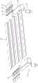
图1为本申请实施例提供的一种折叠桌的折叠过程示意图;FIG. 1 is a schematic diagram of a folding process of a folding table provided in an embodiment of the present application;
图2为本申请实施例提供的一种折叠桌的爆炸图;Figure 2 is an exploded view of a folding table provided in the embodiment of the present application;
图3为本申请实施例提供的第一种折叠桌的折叠原理示意图;Fig. 3 is a schematic diagram of the folding principle of the first folding table provided in the embodiment of the present application;
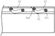
图4为本申请实施例提供的第一种折叠桌在使用状态下的局部结构示意图;FIG. 4 is a schematic diagram of the partial structure of the first folding table in use according to the embodiment of the present application;
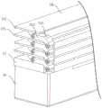
图5为本申请实施例提供的第一种折叠桌在折叠状态下的局部结构示意图;Fig. 5 is a partial structural schematic diagram of the first folding table provided in the embodiment of the present application in a folded state;
图6为本申请实施例提供的第一种折叠桌在折叠状态下的局部结构示意图;Fig. 6 is a partial structural schematic diagram of the first folding table provided in the embodiment of the present application in a folded state;
图7为本申请实施例提供的第一种折叠桌的第一桌板的折叠过程示意图;Fig. 7 is a schematic diagram of the folding process of the first table board of the first folding table provided by the embodiment of the present application;
图8为本申请实施例提供的第一种折叠桌在使用状态下的结构示意图;Fig. 8 is a schematic structural view of the first folding table provided in the embodiment of the present application in a state of use;
图9为本申请实施例提供的第一种折叠桌的侧板装配示意图;Fig. 9 is a schematic diagram of side panel assembly of the first folding table provided by the embodiment of the present application;
图10为本申请实施例提供的第二种折叠桌的折叠原理示意图;Fig. 10 is a schematic diagram of the folding principle of the second folding table provided in the embodiment of the present application;
图11为本申请实施例提供的第三种折叠桌的折叠过程示意图;Fig. 11 is a schematic diagram of the folding process of the third folding table provided in the embodiment of the present application;
图12为本申请实施例提供的第三种折叠桌的折叠原理示意图;Fig. 12 is a schematic diagram of the folding principle of the third folding table provided in the embodiment of the present application;
图13为本申请实施例提供的第三种折叠桌的局部爆炸图;Fig. 13 is a partial exploded view of the third folding table provided by the embodiment of the present application;
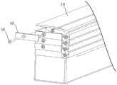
图14为本申请实施例提供的第四种折叠桌的折叠过程示意图;Fig. 14 is a schematic diagram of the folding process of the fourth folding table provided in the embodiment of the present application;
图15为本申请实施例提供的第四种折叠桌的第一局部爆炸图;Fig. 15 is the first partial exploded view of the fourth folding table provided by the embodiment of the present application;
图16为本申请实施例提供的第四种折叠桌的折叠原理示意图;Fig. 16 is a schematic diagram of the folding principle of the fourth folding table provided in the embodiment of the present application;
图17为本申请实施例提供的第四种折叠桌的第二局部爆炸图;Fig. 17 is a second partial exploded view of the fourth folding table provided by the embodiment of the present application;
图18为本申请实施例提供的一种支脚的转动位置示意图;Fig. 18 is a schematic diagram of the rotation position of a support foot provided by the embodiment of the present application;
图19为本申请实施例提供的一种支脚的结构示意图。FIG. 19 is a schematic structural diagram of a support foot provided in an embodiment of the present application.
附图标记:Reference signs:
10、桌板;101、第一伸出部;102、第二伸出部;103、第二凹槽;104、第三凹槽;105、第四凹槽;11、第一桌板;12、第二桌板;13、前桌板;14、后桌板;10. Table; 101. First extension; 102. Second extension; 103. Second groove; 104. Third groove; 105. Fourth groove; 11. First table; 12 , the second table; 13, the front table; 14, the rear table;
20、支脚;21、第一凹槽;22、支脚转轴;23、插座模块;20. Legs; 21. The first groove; 22. The shaft of the legs; 23. The socket module;
30、连接组件;31、转动件;311、第一端部;312、第二端部;313、第一子转动件;314、第二子转动件;315、折角部;32、弹性件;33、连接件;34、转轴件;35、滑动件;351、滑槽;352、滑块;36、螺钉;30. Connecting assembly; 31. Rotating member; 311. First end; 312. Second end; 313. First sub-rotating member; 314. Second sub-rotating member; 315. Angled part; 32. Elastic member; 33. Connector; 34. Shaft; 35. Slider; 351. Slider; 352. Slider; 36. Screw;
40、侧板件;40. Side panels;
X、第一方向;Y、第二方向;Z、第三方向。X, the first direction; Y, the second direction; Z, the third direction.
具体实施方式Detailed ways
为使本申请的技术方案和优点更加清楚,下面将结合附图对本申请实施方式作进一步地详细描述。In order to make the technical solutions and advantages of the present application clearer, the implementation manners of the present application will be further described in detail below in conjunction with the accompanying drawings.
首先需要说明的是,本申请实施例中所涉及的方位名词,如“上”、“下”、“侧”等,一般以图1中所示方位的相对关系为基准,且采用这些方位名词仅仅是为了更清楚地描述结构和结构之间的关系,并不是为了描述绝对的方位。在产品以不同姿态摆放时,方位可能发生变化,例如“上”、“下”可能互换。First of all, it should be noted that the orientation nouns involved in the embodiments of the present application, such as "upper", "lower", "side", etc., are generally based on the relative relationship of the orientation shown in Figure 1, and these orientation nouns are used Just to more clearly describe the structure and the relationship between the structures, not to describe the absolute orientation. When the product is placed in different postures, the orientation may change, for example, "up" and "down" may be interchanged.
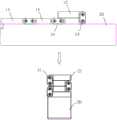
本申请实施例提供了一种折叠桌,图1是该折叠桌的折叠过程示意图,图2是该折叠桌的爆炸图。参见图1和图2,在本申请实施例中,所述折叠桌包括具有多个桌板10的桌面,以及安装在桌面底部的支脚20;多个桌板10通过连接组件30活动连接,支脚20可平行于桌面转动地连接到多个桌板中的第一桌板。其中,在使用状态下,多个桌板10沿第一方向X并行排布,支脚20沿第一方向X延伸,多个桌板10均搭设在所述支脚20上;在折叠状态下,多个桌板沿第二方向Y依次折叠,支脚20转动至延伸方向平行于第三方向Z的位置并支撑第一桌板11,第一方向X、第二方向Y和第三方向Z彼此垂直。An embodiment of the present application provides a folding table. FIG. 1 is a schematic diagram of the folding process of the folding table, and FIG. 2 is an exploded view of the folding table. Referring to Fig. 1 and Fig. 2, in the embodiment of the present application, the folding table includes a desktop with a plurality of
如图1所示,本申请实施例提供的折叠桌,其桌面具有多个桌板10,多个桌板10能够沿第一方向X并行排布组成桌面,相邻的桌板10通过连接组件30活动连接,并能叠置在一起。桌面的底部设有支脚20,支脚20与第一桌板11可转动地连接,转动轴垂直于桌面,因此能够对桌面或者叠置后的多个桌板10进行支撑。其中,第一桌板11和第二桌板12为多个桌板10中位于边缘的两个桌板10,第一桌板11的折叠次序为末位,第二桌板12的折叠次序为首位。第一方向X指的是在使用状态下从第一桌板11指向第二桌板12的方向。As shown in Figure 1, the folding table provided by the embodiment of the present application has a desktop with a plurality of
当用户需要使用桌子时,该折叠桌处于使用状态,此时多个桌板10平铺排列组成桌面,支脚20在桌面的下方同时与所有的桌板10相接触,以对各个桌板10进行支撑,防止桌面变形,用户可以在该桌面上放置物品。当用户使用完毕需要将折叠桌收纳起来时,多个桌板10能够按照排列顺序沿第二方向Y依次折叠,从而在折叠状态下,如图1所示,第二桌板12位于叠置后的多个桌板10的最上方,第一桌板11位于叠置后的多个桌板10的最下方;支脚20能够沿平行于桌面的方向转动,直至支脚20的延伸方向平行于第三方向Z,从而在第一桌板11下方对叠置后的多个桌板10进行支撑。其中,第二方向Y指的是在折叠状态下从第一桌板11指向第二桌板的方向;第三方向Z与第一方向X和第二方向Y均垂直。When the user needs to use the table, the folding table is in the use state. At this time, a plurality of
可选地,第一方向X、第二方向Y和第三方向Z分别平行于桌板10的宽度、厚度和长度方向。Optionally, the first direction X, the second direction Y and the third direction Z are respectively parallel to the width, thickness and length directions of the
综上所述,本申请实施例提供的折叠桌,由于其桌面是由多个桌板10依次排列并连接组成的,能够进行折叠收纳;其支脚20能够相对于桌面转动,旋转至第一桌板11下方进行收起,因此该折叠桌的桌面和支脚20均能折叠收纳,使得处于折叠状态的折叠桌所占用的空间更小,便于出行携带,也降低了运输成本。In summary, the folding table provided by the embodiment of the present application can be folded and stored because its desktop is composed of a plurality of
为使本申请的技术方案和优点更加清楚,下面结合图1至图18,对本申请实施例提供的折叠桌进行进一步的介绍和说明。In order to make the technical solutions and advantages of the present application clearer, the folding table provided by the embodiment of the present application will be further introduced and explained below in conjunction with FIGS. 1 to 18 .
首先,对本申请实施例提供的折叠桌的支脚20进行介绍。如图1所示,在本申请的一些实施例中,折叠桌可以作为显示器增高架使用,此时支脚的长度大于宽度和高度,其中长度指的是在折叠桌为使用状态时,支脚在与多个桌板的排列方向平行的方向上的尺寸;高度指的是支脚在垂直于桌面的方向上的尺寸;宽度则是支脚在与长度方向和高度方向均垂直的方向上的尺寸。当然,在本申请的其它实施例中,折叠桌也可以具有其他用途,例如作为餐桌、户外桌等使用,此时支脚的高度可以大于长度和高度。Firstly, the
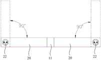
在本申请的一些实施例中,支脚20的数量为两个,两个支脚20在第一桌板11的底部两侧对称设置。每个支脚20具有在使用状态下用于支撑第二桌板12的末端,从使用状态到折叠状态,两个支脚20的转动方向相反且末端彼此靠近。In some embodiments of the present application, the number of the
如图18所示,两个支脚20分别连接在第一桌板11的底部两侧,并关于第一桌板10的长度的中线对称设置,每个支脚20与第一桌板11可转动地连接,转动轴垂直于桌面。可选地,每个支脚20的转动角度范围为0-90度。As shown in Figure 18, two
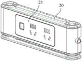
在本申请的一些实施例中,如图19所示,折叠桌还包括插座模块23,该插座模块23装设在至少一个支脚20上,使得该折叠桌能够提供充电插孔,以方便用户通过该插座模块23取电和使用。In some embodiments of the present application, as shown in FIG. 19 , the folding table further includes a
接下来,对本申请实施例提供的折叠桌的桌面进行介绍。在本申请实施例中,相邻的桌板10通过连接组件30活动连接,因而能够折叠在一起。下面结合附图3-17,基于几种可能的连接组件30的结构,对本申请实施例提供的折叠桌的桌面折叠原理进行更为详细的说明。Next, the desktop of the folding table provided in the embodiment of the present application is introduced. In the embodiment of the present application, the
在本申请的一些实施例中,连接组件30包括转动件31,转动件31的两个端部分别可转动地连接在前桌板13和后桌板14的侧壁上,其中前桌板13和后桌板14相邻,且前桌板13的折叠次序在后桌板14之前。转动件31的任一端部在转动时,所绕的转动轴平行于第三方向Z。In some embodiments of the present application, the connecting
在一种可能的设计中,如图3和图4所示,转动件31的第一端部311连接在前桌板13的中间位置和第一端之间,转动件31的第二端部312连接在后桌板14的第一端,其中桌板10的第一端位于桌板10的第二端的第一方向X上。在使用状态下,转动件31的第一端部311的高度低于第二端部312的高度;在折叠状态下,前桌板13的底面叠压在后桌板14的顶面上。In a possible design, as shown in FIGS. 3 and 4 , the
其中,以图3中所示出的方位为例,由于多个桌板10是按照右到左的顺序依次折叠的,因此最左侧的桌板10为第一桌板11,最右侧的桌板10为第二桌板12,第一方向指的是从左侧指向右侧。对应地,桌板10的第一端指的是右端,桌板10的第二端指的是左端。Wherein, taking the orientation shown in Fig. 3 as an example, since a plurality of
需要说明的是,在本申请实施例中,多个桌板10的厚度均相同,并且在使用状态下,各个桌板10的顶面均齐平,底面均齐平。转动件31的端部的高度,可以理解为该端部相对于各个桌板10的底面的高度,高度越高,则越远离底面,越接近顶面。转动件31的第一端部311连接在前桌板13的中间位置和第一端之间,转动件31的第二端部312连接在后桌板14的第一端,并且在使用状态下,第一端部311的高度低于第二端部312的高度,因此确保了前桌板13能够转动到位,进而在折叠状态下前桌板13的底面能够叠压在后桌板14的顶面上。It should be noted that, in the embodiment of the present application, the thicknesses of the plurality of
需要说明的是,转动件31的第一端部311指的是其与前桌板13的连接处,第二端部312指的是其与后桌板14的连接处。It should be noted that the
以图3中所示出的五个桌板10所组成的桌面为例,其中右起第一个(即位于最右侧)桌板为第二桌板12,右起第五个(即位于最左侧)桌板为第一桌板11。在使用状态下,每个转动件31的第一端部311位于第二端部312的右下方,当桌面需要折叠时,右起第一个桌板向上移动并同时相对于转动件31转动,从而其底面叠压在右起第二个桌板的顶面上,此时与这两个桌板相连的转动件31的第一端部311转动至第二端部312的左上方。接下来,右起第二个桌板以同样的方式转动,以使其底面叠压在右起第三个桌板的顶面上,以此类推,直至右起第四个桌板的底面叠压在右起第五个桌板的顶面上,至此完成桌面的折叠。Take the table top formed by five
可选地,在折叠状态下,前桌板13的第二端与后桌板14的第二端在第二方向Y上对齐。Optionally, in the folded state, the second end of the
在本申请的一些实施例中,如图5和图6所示,多个桌板10中除第一桌板11外,其余的桌板10均具有第一伸出部101,第一伸出部101自桌板10的顶面平行于第三方向Z伸出;转动件31包括第一子转动件313和第二子转动件314,第一子转动件313与前桌板13相连,第二子转动件314和后桌板14相连,第一子转动件313和第二子转动件314倾斜相接而形成折角部315。在使用状态下,折角部315靠近支脚20的顶面或与支脚20的顶面相接触;在折叠状态下,折角部315远离支脚20的顶面,第一子转动件313位于前桌板13的第一伸出部101和后桌板14的第一伸出部101之间,并且第一子转动件313的内表面叠压在后桌板14的第一伸出部101的顶面上。In some embodiments of the present application, as shown in FIG. 5 and FIG. 6 , among the plurality of
如图1所示,在使用状态下,从各个桌板10的顶面伸出的第一伸出部101能对各个转动件31进行遮挡,从而在垂直于桌面的方向向下看,不能看到各个转动件31,提高了桌面的整体性。并且,当桌面上放置有例如零件等小体积物品或者堆积有砂砾等颗粒物时,由于第一伸出部101的遮挡,它们从桌面上掉落时不会卡入转动件31的内部而造成转动件31损坏,因此第一伸出部101还具有对转动件31的保护作用。如图5所示,在折叠状态下,各个转动件31被收纳在其所连接的两个桌板10的第一伸出部101之间,因此提高了折叠后的桌板10的整体性,同时第一伸出部101也会在折叠状态下对转动件31进行保护,防止其磕碰变形,具有实用性。As shown in Figure 1, in the state of use, the first protruding
在本申请的一些实施例中,如图6所示,支脚20的顶面开设有第一凹槽21,第一凹槽21和折角部315位置对应;其中在使用状态下,折角部315位于第一凹槽21内。In some embodiments of the present application, as shown in FIG. 6 , a
第一凹槽21用于收容和避让折角部315,以避免支脚20对转动件31的转动造成影响。The
在本申请的一些实施例中,如图7和图8所示,多个桌板10中除第一桌板11外,其余的桌板10均具有第二伸出部102,第二伸出部102自桌板10的顶面平行于第一方向X伸出。多个桌板10中除第二桌板12外,其余的桌板10的顶面均开设有第二凹槽103,第二凹槽103延伸至桌板10的第一端的边缘,第二凹槽103的深度和第一伸出部101的厚度相同;在使用状态下,前桌板13的第二伸出部102位于后桌板14的第二凹槽103内。In some embodiments of the present application, as shown in FIG. 7 and FIG. 8 , except for the
其中,第二凹槽103的深度方向平行于第一伸出部101的厚度方向,且平行于桌板10的厚度方向。由于第二凹槽103的深度等于第一伸出部101的厚度,因此如图5所示,第一伸出部101对应第二凹槽103的位置被挖空。Wherein, the depth direction of the
在本申请的一些实施例中,如图9所示,折叠桌还包括多个侧板件40,多个侧板件40一一对应地连接到多个桌板10的侧壁上。其中,侧板件40位于转动件31远离桌板10的侧壁的一侧,用于遮挡第一子转动件313的至少一部分。In some embodiments of the present application, as shown in FIG. 9 , the folding table further includes a plurality of
侧板件40能与第一伸出部101配合围成容置空间,第一子转动件313的至少一部分位于该容置空间内,达到隐藏的效果,从而侧板件40一方面起到对转动件31的保护作用,另一方面也提高了桌面在折叠前后的美观度。The
可选地,侧板件40和转动件31均通过螺钉36固定在对应的桌板10的侧壁上,并且转动件31的两个端部均能相对于对应的螺钉36转动。Optionally, both the
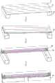
在另一种可能的设计中,如图10所示,转动件31的两个端部分别连接在前桌板13和后桌板14彼此靠近的一端;在使用状态下,转动件31的两个端部位于同一高度;在折叠状态下,前桌板13的顶面叠压在后桌板14的顶面上,或者前桌板13的底面叠压在后桌板14的底面上。In another possible design, as shown in FIG. 10 , the two ends of the rotating
以图10中所示出的四个桌板10所组成的桌面为例,其中右起第一个(即位于最右侧)桌板为第二桌板12,右起第四个(即位于最左侧)桌板为第一桌板11。在使用状态下,每个转动件31的第一端部和第二端部位于同一水平高度,当桌面需要折叠时,右起第一个桌板基于其所连接的转动件31的第一端部逆时针转动90度,并带动该转动件基于第二端部逆时针转动90度,从而其顶面叠压在右起第二个桌板的顶面上,此时转动件31的第一端部和第二端部在竖直方向上排列。接下来,右起第二个桌板以类似的方式转动,但转动方向变成顺时针,以使其底面叠置在右起第三个桌板的底面上。以此类推,右起第三个桌板的转动方向与右起第一个桌板的转动方式相同,直至右起第三个桌板的顶面叠压在右起第四个桌板的顶面上,至此完成桌面的折叠。在本申请的另一些实施例中,如图11和12所示,连接组件30包括弹性件32,弹性件32的两个端部分别可转动地连接在前桌板13和后桌板14在使用状态下相对的板壁上;其中,弹性件32的任一端部在转动时,所绕的转动轴平行于桌面所在的平面,并且垂直于多个桌板10的排列方向;弹性件32用于提供驱使两个端部彼此靠近的弹力。Take the desktop composed of four
可选地,弹性件32可以选用弹片。当折叠桌处于使用状态时,弹性件32的两端位于同一高度,并且分别拉紧前桌板13和后桌板14,以减小二者之间的缝隙。在前桌板13折叠的过程中,随着前桌板13的转动,前桌板13和后桌板14之间的距离增大,引起弹性件32的形变,使得弹性件32提供的弹力增大,直至前桌板13的顶面或底面和对应的后桌板14的顶面或底面相接触,此时弹性件仍拉紧前桌板13和后桌板14,使得在折叠状态下前桌板13和后桌板14之间的缝隙也较小。并且,由于在折叠过程中,在弹性件32的弹力作用下,前桌板13和后桌板14始终保持彼此拉紧,因此还提高了用户折叠桌板10时的手感,提高了使用体验。Optionally, the
以图12中所示出的四个桌板10所组成的桌面为例,其中右起第一个(即位于最右侧)桌板为第二桌板12,右起第四个(即位于最左侧)桌板为第一桌板11。在使用状态下,每个弹性件32的两个端部位于同一水平高度,弹力方向平行于其所连接的两个桌板的排列方向,因此多个桌板在使用状态下保持稳定不会移动;当桌面需要折叠时,右起第一个桌板(前桌板13)向右起第二个桌板14移动,并同时基于其所连接的弹性件32的端部逆时针转动,直至其顶面叠压在右起第二个桌板14的顶面上,在该折叠过程中,由于弹力方向与两个桌板的排列方向可能不一致,因此会导致右起第一个桌板(前桌板13)有在弹力作用下移动或转动的趋势,与用户的手部产生对抗,从而保证了折叠过程中的良好手感;在右起第一个桌板(前桌板13)的顶面叠压在右起第二个桌板14的顶面上时,弹性件32的两个端部在竖直方向上排列,再次与两个桌板的排列方向一致,因此这两个桌板的折叠完毕后也能保持稳定不移动。接下来,右起第二个桌板以类似的方式转动,但转动方向变成顺时针,以使其底面叠置在右起第三个桌板的底面上。以此类推,右起第三个桌板的转动方向与右起第一个桌板的转动方式相同,直至右起第三个桌板的顶面叠压在右起第四个桌板的顶面上,至此完成桌面的折叠。Take the desktop composed of four
需要说明的是,弹性件32的端部指的是其与对应的桌板10的连接处。It should be noted that the end of the
参见图12和图13,在一些实施例中,连接组件30还包括两个连接件33;前桌板13和后桌板14在使用状态下相对的板壁上均开设有第三凹槽104,第三凹槽104与对应的桌板10的底面连通;两个连接件33分别位于前桌板13和后桌板14的第三凹槽104内,连接件33的两端分别连接在第三凹槽104的相对的槽壁上;弹性件32的两个端部分别可转动地套设在两个连接件33上;其中在折叠状态下,弹性件32驱使两个连接件33彼此靠近,前桌板13的顶面叠压在后桌板14的顶面上,或者,前桌板13的底面叠压在后桌板14的底面上。Referring to Fig. 12 and Fig. 13, in some embodiments, the
可选地,连接件33为连接轴。弹性件32的两端向内收卷成贯通的筒形结构,连接轴穿过对应的筒形结构后,两端分别连接在第三凹槽104的相对的槽壁上,从而将弹性件32对应的端部固定在对应的桌板10上。弹性件32的筒形结构可相对于连接轴转动。Optionally, the connecting
在一些实施例中,如图12所示,当前桌板13被配置为使顶面叠压在后桌板14的顶面上时,弹性件32在在使用状态下相对的板壁上的连接位置更靠近底面;当前桌板13被配置为使底面叠压在后桌板14的底面上时,弹性件32在在使用状态下相对的板壁上的连接位置更靠近顶面。In some embodiments, as shown in FIG. 12 , when the front table 13 is configured so that the top surface is laminated on the top surface of the rear table 14 , the
通过采用上述布置方式,弹性件32的两端在桌板10转动过程中所产生的相对位移更大,弹性件32的形变量更大,进而提供的弹力更大,因而保证了前桌板13在转动过程中始终是与后桌板14拉紧的。By adopting the above arrangement, the relative displacement generated by the two ends of the
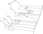
在本申请的另一些实施例中,如图14和图15所示,连接组件30包括转轴件34和滑动件35;转轴件34的一端可转动地连接到后桌板14,转轴件34的另一端与滑动件35相连,其中转轴件34的转动轴平行于桌面所在的平面,并且垂直于多个桌板10的排列方向;滑动件35适于与前桌板13滑动配合,滑动件35的滑动方向平行于多个桌板10的排列方向。In some other embodiments of the present application, as shown in Fig. 14 and Fig. 15, the
在折叠桌从使用状态转变为折叠状态时,前桌板13先是带动转轴件34相对于后桌板14转动,之后前桌板13与滑动件35滑动配合,从而移动至后桌板14上对应的叠置位置。When the folding table changes from the use state to the folded state, the
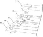
在一些实施例中,如图15和图16所示,滑动件35包括滑槽351,以及位于滑槽351内的滑块352,滑槽351和滑块352中的一种设置在前桌板13上,另一种与转轴件34相连,滑槽351的延伸方向平行于第一方向X;在使用状态下,滑块352的高度高于转轴件34的高度,滑块352位于滑槽351的第一端,其中滑槽351的第一端为在使用状态下更靠近后桌板14的一端;在折叠状态下,前桌板13的底面叠压在后桌板14的顶面上,滑块352位于滑槽351的第二端,滑槽351的第二端与第一端相对。In some embodiments, as shown in FIG. 15 and FIG. 16 , the sliding
以图12中所示出的五个桌板所组成的桌面为例(部分转轴件和滑动件未在图中示出),其中右起第一个桌板(前桌板13)上开设有滑槽351,右起第二个桌板(后桌板14)上连接有转轴件34。在使用状态下,每个滑块352的高度高于转轴件34的端部的高度,滑块352位于滑槽351的左端;当桌面需要折叠时,右起第一个桌板13带动转轴件34相对于右起第二个桌板14转动,当右起第一个桌板13的底面与右起第二个桌板14的顶面平齐或高于右起第二个桌板14的顶面时,向左推动右起第一个桌板13,使其基于滑槽351和滑块352的滑动配合移动至右起第二个桌板14的正上方,此时其底面叠压在右起第二个桌板14的顶面上,滑块352位于滑槽351的右端。接下来,右起第二个桌板14以同样的方式带动转轴件34转动和基于滑动件35滑动,以使其底面叠压在右起第三个桌板的顶面上。以此类推,直至右起第四个桌板的底面叠压在右起第五个桌板的顶面上,至此完成桌面的折叠。Take the desktop composed of five table boards shown in Figure 12 as an example (part of the shaft and the sliding part are not shown in the figure), wherein the first table board (front table board 13) from the right is provided with The
需要说明的是,转轴件34的端部指的是其与对应的桌板10的连接处。It should be noted that the end of the
在一些实施例中,如图17所示,多个桌板10中除位于边缘的两个桌板10外,其余的桌板10的底面均开设有第四凹槽105和滑槽351,第四凹槽105和滑槽351在桌板10的底面错开设置;第四凹槽105延伸至桌板10的第一端的边缘,桌板10的第一端位于桌板10的第二端的第一方向X上;转轴件34的两端可转动地连接在第四凹槽105的相对的槽壁上;滑槽351的两端分别延伸至所在的桌板10的第一端的边缘和第二端的边缘。In some embodiments, as shown in FIG. 17 , among the plurality of
综上所述,本申请实施例提供的折叠桌,由于其桌面具有通过连接组件活动连接的多个桌板,能够实现依次折叠;第一桌板的底部安装有能够平行于桌面转动的支脚,因此在该折叠桌需要使用时,可以先转动支脚使其沿多个桌板的第一方向延伸,然后将折叠在一起的多个桌板依次打开,使得各个桌板沿第一方向并行排布组成桌面,并且均搭设在支脚上,由支脚对桌面进行支撑;当该折叠桌使用完毕后,可以先将多个桌板沿第二方向依次折叠,使多个桌板叠置在第一桌板的顶面上,然后转动支脚,使得支脚沿第三方向延伸,并支撑第一桌板,其中第一方向、第二方向和第三方向彼此垂直。因而,本申请实施例所提供的折叠桌,其桌面和支脚均能折叠收纳,因而便于携带,降低了运输成本。In summary, the folding table provided by the embodiment of the present application can be folded sequentially because its desktop has a plurality of table boards movably connected by connecting components; the bottom of the first table board is equipped with feet that can rotate parallel to the table top, Therefore, when the folding table needs to be used, the legs can be rotated to extend along the first direction of the plurality of table boards, and then the folded table boards are opened in sequence, so that each table board is arranged in parallel along the first direction The desktop is formed, and all of them are erected on the feet, and the desktop is supported by the feet; when the folding table is used up, the multiple table boards can be folded sequentially along the second direction, so that the multiple table boards are stacked on the first table. On the top surface of the board, the legs are then rotated so that the legs extend along a third direction and support the first table top, wherein the first direction, the second direction and the third direction are perpendicular to each other. Therefore, in the folding table provided by the embodiment of the present application, both the table top and the legs can be folded and stored, so that it is easy to carry and reduces the transportation cost.
在本申请中,应该理解到,术语“第一”、“第二”、“第三”等仅用于描述目的,而不能理解为指示或暗示相对重要性或者隐含指明所指示的技术特征的数量。In this application, it should be understood that the terms "first", "second", "third" and so on are used for descriptive purposes only, and cannot be interpreted as indicating or implying relative importance or implicitly indicating the indicated technical features quantity.
以上所述仅是为了便于本领域的技术人员理解本申请的技术方案,并不用以限制本申请。凡在本申请的精神和原则之内,所作的任何修改、等同替换、改进等,均应包含在本申请的保护范围。The above description is only for those skilled in the art to understand the technical solutions of the present application, and is not intended to limit the present application. Any modifications, equivalent replacements, improvements, etc. made within the spirit and principles of this application shall be included in the protection scope of this application.
Claims (15)
Translated fromChinesePriority Applications (1)
| Application Number | Priority Date | Filing Date | Title |
|---|---|---|---|
| CN202320344296.3UCN219330947U (en) | 2023-02-17 | 2023-02-17 | folding table |
Applications Claiming Priority (1)
| Application Number | Priority Date | Filing Date | Title |
|---|---|---|---|
| CN202320344296.3UCN219330947U (en) | 2023-02-17 | 2023-02-17 | folding table |
Publications (1)
| Publication Number | Publication Date |
|---|---|
| CN219330947Utrue CN219330947U (en) | 2023-07-14 |
Family
ID=87106098
Family Applications (1)
| Application Number | Title | Priority Date | Filing Date |
|---|---|---|---|
| CN202320344296.3UActiveCN219330947U (en) | 2023-02-17 | 2023-02-17 | folding table |
Country Status (1)
| Country | Link |
|---|---|
| CN (1) | CN219330947U (en) |
Cited By (1)
| Publication number | Priority date | Publication date | Assignee | Title |
|---|---|---|---|---|
| CN119908551A (en)* | 2025-04-01 | 2025-05-02 | 江苏焜驰汽车制造有限公司 | Folding table for car |
- 2023
- 2023-02-17CNCN202320344296.3Upatent/CN219330947U/enactiveActive
Cited By (2)
| Publication number | Priority date | Publication date | Assignee | Title |
|---|---|---|---|---|
| CN119908551A (en)* | 2025-04-01 | 2025-05-02 | 江苏焜驰汽车制造有限公司 | Folding table for car |
| CN119908551B (en)* | 2025-04-01 | 2025-07-29 | 江苏焜驰汽车制造有限公司 | Folding table for automobile |
Similar Documents
| Publication | Publication Date | Title |
|---|---|---|
| US9141137B2 (en) | Electronic device with keyboard | |
| US20120298017A1 (en) | Desk assembly | |
| CN219330947U (en) | folding table | |
| CN204764272U (en) | Hidden folding desk | |
| US20240094774A1 (en) | Foldable electronic apparatus | |
| CN104605635A (en) | Multifunctional bedside cabinet | |
| TWM329121U (en) | Pivot with multiple screens and pivoting structure thereof | |
| WO2022267128A1 (en) | Work table | |
| CN204378461U (en) | Multifunction bedside cabinet | |
| CN204026053U (en) | A multi-directional stent | |
| US20040060485A1 (en) | Combination computer desk | |
| CN217090087U (en) | Foldable and openable writing board | |
| CN210804191U (en) | Notebook computer | |
| TWM628907U (en) | screen rotation structure | |
| CN211554896U (en) | Vertical keyboard | |
| CN220859697U (en) | A multifunctional desk for education and training | |
| CN100463624C (en) | Writing desk with drawers connected to brackets | |
| CN209660808U (en) | A kind of Novel laptop computer desk | |
| CN219327955U (en) | Auxiliary base for computer display | |
| CN222486571U (en) | Multimedia platform with holographic projection function | |
| CN216984040U (en) | Office table convenient for hiding computer | |
| CN223041097U (en) | A foldable table that is easy to store | |
| CN219515628U (en) | Read-write rack | |
| CN115886437B (en) | A three-dimensional storage work platform table | |
| CN216453920U (en) | A polygonal combination splicing computer desk |
Legal Events
| Date | Code | Title | Description |
|---|---|---|---|
| GR01 | Patent grant | ||
| GR01 | Patent grant |