CN219289563U - Endoscopic anastomat - Google Patents
Endoscopic anastomatDownload PDFInfo
- Publication number
- CN219289563U CN219289563UCN202320266759.9UCN202320266759UCN219289563UCN 219289563 UCN219289563 UCN 219289563UCN 202320266759 UCN202320266759 UCN 202320266759UCN 219289563 UCN219289563 UCN 219289563U
- Authority
- CN
- China
- Prior art keywords
- cutting knife
- nail
- assembly
- protrusions
- elastic
- Prior art date
- Legal status (The legal status is an assumption and is not a legal conclusion. Google has not performed a legal analysis and makes no representation as to the accuracy of the status listed.)
- Active
Links
- 238000005520cutting processMethods0.000claimsabstractdescription62
- 238000005452bendingMethods0.000claimsdescription3
- 238000009527percussionMethods0.000claimsdescription2
- 230000002159abnormal effectEffects0.000abstractdescription6
- 208000027418Wounds and injuryDiseases0.000abstractdescription2
- 230000006378damageEffects0.000abstractdescription2
- 208000014674injuryDiseases0.000abstractdescription2
- 238000010586diagramMethods0.000description10
- 230000000694effectsEffects0.000description3
- 238000010304firingMethods0.000description2
- 238000002324minimally invasive surgeryMethods0.000description2
- 230000004048modificationEffects0.000description2
- 238000012986modificationMethods0.000description2
- 238000001356surgical procedureMethods0.000description2
- 206010066902Surgical failureDiseases0.000description1
- 230000006978adaptationEffects0.000description1
- 238000005516engineering processMethods0.000description1
- 230000014509gene expressionEffects0.000description1
- 230000003902lesionEffects0.000description1
- 238000000034methodMethods0.000description1
- 238000002271resectionMethods0.000description1
Images


Landscapes
- Surgical Instruments (AREA)
Abstract
Description
Translated fromChinese技术领域technical field
本实用新型涉及医疗器械领域,特别涉及一种腔镜吻合器。The utility model relates to the field of medical instruments, in particular to a laparoscopic stapler.
背景技术Background technique
目前,微创手术占据了外科手术中的重要地位。腔镜吻合器是微创手术中常用的手术器械。腔镜吻合器的工作原理是通过组件钳口夹持在病灶部位附近的特定位置,进行切除,切除的同时进行缝合。在一台手术中,需要根据组织的厚度、长度来选择不同型号的工作组件,难免忘记工作组件是否已经被使用过。如果工作组件中没有检测钉匣的机构,不能确认钉匣是否已经安装或者安装的钉匣已经被使用,在没有安装钉匣或者钉匣已经进行一次缝合的情况下,如果击发切割刀,则会只切割组织而无法缝合或者切割已经缝合好的组织,从而导致手术失败或者二次手术。At present, minimally invasive surgery occupies an important position in surgery. Laparoscopic stapler is a commonly used surgical instrument in minimally invasive surgery. The working principle of the laparoscopic stapler is to clamp it at a specific position near the lesion through the jaws of the components, perform resection, and suture at the same time. In an operation, it is necessary to select different types of working components according to the thickness and length of the tissue, and it is inevitable to forget whether the working components have been used. If there is no mechanism for detecting the nail box in the working assembly, it cannot be confirmed whether the nail box has been installed or the installed nail box has been used. Only cutting tissue without suturing or cutting tissue that has been sutured, resulting in surgical failure or secondary surgery.
实用新型内容Utility model content
本实用新型要解决的是现有技术中钉匣状态不正常所带来的手术风险的技术问题。What the utility model aims to solve is the technical problem of the operation risk caused by the abnormal state of the nail box in the prior art.
为解决上述技术问题,本实用新型提供的技术方案如下:In order to solve the problems of the technologies described above, the technical solutions provided by the utility model are as follows:
一种腔镜吻合器,包括工作组件,工作组件包括抵钉座、钉匣组件、钉匣底座和切割刀,还包括切割刀限制组件,切割刀限制组件用于在未安装钉匣组件或钉匣组件使用过一次后限制切割刀向远端运动,切割刀限制组件包括:设置于切割刀两侧的凸起部、设置于钉匣底座上的凹槽和凸台、弹性部件,其中凸起部与凹槽对应设置,弹性部件对凸起部施加弹力,在弹性部件的作用下,凸起部能够卡入凹槽内且抵住凸台的端面。A laparoscopic stapler, including a working assembly, the working assembly includes a nail abutment, a nail box assembly, a nail box base and a cutting knife, and also includes a cutting knife limiting assembly, the cutting knife limiting assembly is used for when the nail box assembly or nails are not installed. After the cartridge assembly has been used once, the cutting knife is restricted from moving to the far end. The cutting knife limiting assembly includes: protrusions arranged on both sides of the cutting knife, grooves and bosses arranged on the base of the nail box, elastic parts, in which the protrusions The portion is arranged corresponding to the groove, and the elastic component exerts elastic force on the protrusion, and under the action of the elastic component, the protrusion can be inserted into the groove and abut against the end surface of the boss.
进一步地,凸起部、凸台和凹槽分别为两个,两个凸起部分别设置于切割刀两侧,凹槽和凸台分别与凸起部对应设置。Further, there are two protrusions, protrusions and grooves respectively, the two protrusions are respectively arranged on both sides of the cutting knife, and the grooves and protrusions are respectively arranged corresponding to the protrusions.
进一步地,切割刀还包括上刀架和下刀架,下刀架穿过钉匣底座上的矩形孔,使切割刀进入钉匣底座上的长条轨道。Further, the cutting knife also includes an upper knife rest and a lower knife rest, and the lower knife rest passes through the rectangular hole on the base of the nail magazine, so that the cutting knife enters the elongated track on the base of the nail magazine.
进一步地,工作组件还包括推钉滑块,推钉滑块具有支撑面,切割刀的前端搭在支撑面上,支撑面距离推钉滑块的底面具有一定的高度,从而将切割刀前端抬起,当击发力推动切割刀向远端运动时,凸起部可以克服弹性部的弹力,使上刀架进入抵钉座的轨道,推动推钉滑块向组件远端移动,进行缝合切割。Further, the working assembly also includes a push nail slider, the push nail slider has a supporting surface, the front end of the cutting knife rides on the supporting surface, and the supporting surface has a certain height from the bottom surface of the pushing nail slider, so that the front end of the cutting knife is lifted When the firing force pushes the cutting knife to move to the far end, the raised part can overcome the elastic force of the elastic part, so that the upper knife rest enters the track of the nail seat, and pushes the push nail slider to move to the far end of the component to perform suture cutting .
弹性部件为弹片,弹片包括平整段和折弯段,平整段固定在钉匣底座上,折弯段设有开口部,切割刀的至少一部分设置于开口部内,折弯部能够对凸起部施加弹力。The elastic part is a shrapnel, and the shrapnel includes a flat section and a bent section, the flat section is fixed on the base of the nail box, the bent section is provided with an opening, at least a part of the cutting knife is arranged in the opening, and the bent section can apply pressure to the raised section. elastic.
采用这样的设计后,本实用新型至少具有以下优点:After adopting such design, the utility model has the following advantages at least:
(1)本实用新型通过设置切割刀限制组件限制在钉匣组件非正常状态下切割刀向前移动从而可以避免手术二次伤害。(1) The utility model restricts the forward movement of the cutting knife under the abnormal state of the nail box assembly by setting the cutting knife limiting assembly so as to avoid the secondary injury of the operation.
(2)本实用新型结构简单,效果好,且成本低,易工艺实现。(2) The utility model has the advantages of simple structure, good effect, low cost and easy technological realization.
附图说明Description of drawings
上述仅是本实用新型技术方案的概述,为了能够更清楚了解本实用新型的技术手段,以下结合附图与具体实施方式对本实用新型作进一步的详细说明。The above is only an overview of the technical solution of the utility model. In order to better understand the technical means of the utility model, the utility model will be further described in detail below in conjunction with the accompanying drawings and specific embodiments.
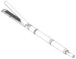
图1是本实用新型工作组件结构示意图;Fig. 1 is the structural representation of working assembly of the present utility model;
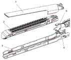
图2是本实用新型工作组件分解示意图;Fig. 2 is an exploded schematic view of the working components of the utility model;
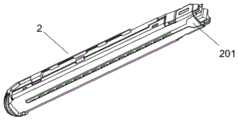
图3是本实用新型钉匣组件结构示意图;Fig. 3 is a structural schematic diagram of the utility model nail box assembly;
图4是本实用新型弹性部件结构示意图;Fig. 4 is a structural schematic diagram of the elastic part of the utility model;
图5是本实用新型弹性部件与钉匣底座装配示意图;Fig. 5 is a schematic diagram of the assembly of the elastic part of the utility model and the base of the nail box;
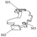
图6是本实用新型切割刀结构示意图;Fig. 6 is a structural schematic diagram of the utility model cutting knife;
图7是本实用新型切割刀与钉匣底座装配示意图;Fig. 7 is a schematic diagram of the assembly of the cutting knife and the base of the nail box of the utility model;
图8为本实用新型推钉滑块结构示意图;Fig. 8 is a structural schematic diagram of the push nail slider of the utility model;
图9为本实用新型切割刀初始状态示意图;Fig. 9 is a schematic diagram of the initial state of the cutting knife of the utility model;
图10为本实用新型钉匣组件正常状态示意图;Fig. 10 is a schematic diagram of the normal state of the nail box assembly of the present utility model;
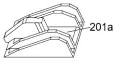
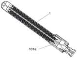
图11为本实用新型抵钉座结构示意图;Fig. 11 is a schematic diagram of the structure of the nail abutment seat of the present invention;
图12为本实用新型钉匣底座结构示意图;Fig. 12 is a structural schematic diagram of the nail box base of the utility model;
附图标记,1抵钉座、2钉匣组件、3钉匣底座、4弹性部件、5切割刀、101a轨道、201推钉滑块、201a支撑面、301凸台、302凹槽、501上刀架、502下刀架、503凸起部;Reference numerals, 1 anvil, 2 nail box assembly, 3 nail box base, 4 elastic part, 5 cutting knife, 101a track, 201 push nail slider, 201a supporting surface, 301 boss, 302 groove, 501 top Knife holder, 502 lower knife holder, 503 raised part;
具体实施方式Detailed ways
下面将结合本实用新型实施例中的附图,对本实用新型实施例中的技术方案进行清楚、完整的描述,显然,所描述的实施例仅仅是本实用新型一部分实施例,而不是全部的实施例。基于本实用新型中的实施例,本领域普通技术人员在没有作出创造性劳动前提下所获得的所有其他实施例,都属于本实用新型保护的范围。The technical solutions in the embodiments of the present invention will be clearly and completely described below in conjunction with the accompanying drawings in the embodiments of the present invention. Obviously, the described embodiments are only part of the embodiments of the present invention, not all of them. example. Based on the embodiments of the present utility model, all other embodiments obtained by persons of ordinary skill in the art without making creative efforts belong to the scope of protection of the present utility model.
在本文中,“上”、“下”等仅用于表示相关部分之间的相对位置关系,而非限定这些相关部分的绝对位置。Herein, "upper", "lower" and the like are only used to indicate the relative positional relationship between related parts, rather than to limit the absolute positions of these related parts.
以下每个部件靠近操作者的一端定义为近端,远离操作者的一端定义为远端。该近端、远端的表达只用于使描述简单、清楚,不应该理解为对本实用新型的任何限定。The end of each of the following components close to the operator is defined as the proximal end, and the end far away from the operator is defined as the distal end. The expressions of proximal end and distal end are only used to make the description simple and clear, and should not be understood as any limitation to the present invention.
参见附图1-12,一种腔镜吻合器,包括工作组件,工作组件包括抵钉座1、钉匣组件2、钉匣底座3和切割刀5,还包括切割刀限制组件,切割刀限制组件用于在未安装钉匣组件或钉匣组件使用过一次后限制切割刀向远端运动,切割刀限制组件包括:设置于切割刀5两侧的凸起部503、设置于钉匣底座3上的凹槽302和凸台301、弹性部件4,其中凸起部503与凹槽302对应设置,弹性部件4对凸起部503施加弹力,在弹性部件4的作用下,凸起部503能够卡入凹槽302内且抵住凸台301的端面。优选地,凸起部、凸台和凹槽分别为两个,两个凸起部分别设置于切割刀两侧,凹槽和凸台分别与凸起部对应设置。凸起部和凹槽的形状没有具体限制,只要能保证凸起部可以卡入凹槽即可。Referring to accompanying drawings 1-12, a laparoscopic stapler includes a working assembly. The working assembly includes an
参见附图6-7,切割刀5还包括上刀架501和下刀架502,下刀架502穿过钉匣底座3上的矩形孔,使切割刀进入钉匣底座3上的长条轨道。切割刀向远端运动,刀架501可以进入抵钉座1的轨道101a,从而切割刀可以沿着钉匣底座3上的长条轨道和抵钉座上的轨道101a向远端运动实现对组织的切割。Referring to accompanying drawings 6-7, the
工作组件还包括推钉滑块201,参见附图8,推钉滑块201具有支撑面201a,切割刀的前端搭在支撑面201a上,支撑面距离推钉滑块201的底面具有一定的高度,从而将切割刀前端抬起,当击发力推动切割刀5向远端运动时,凸起部503可以克服弹性部4的弹力,使上刀架501进入抵钉座1的轨道101a,从而可以推动推钉滑块201向组件远端移动,进行缝合切割操作。The working assembly also includes a
优选地,参见附图4-5,弹性部件为弹片,弹片包括平整段和折弯段,平整段固定在钉匣底座3上,折弯段设有开口部,切割刀5的至少一部分设置于开口部内,折弯部能够对凸起部503施加弹力,使得凸起部可以卡入凹槽内,抵住凸台301的端面,从而阻止切割刀向远端运动。Preferably, referring to accompanying drawings 4-5, the elastic member is a shrapnel, and the shrapnel includes a flat section and a bent section, the flat section is fixed on the
在装配工作组件时,首先将保险弹片4的平整段固定在钉匣底座3上,下刀架502穿过钉匣底座3上的矩形孔,使切割刀5进入钉匣底座3上的长条轨道。将抵钉座1与钉匣组件2装配上,完成工作组件装配。When assembling the working components, first fix the flat section of the
参见附图9-12,钉匣组件2正常情况:钉匣组件正确安装并且没有使用过,由于切割刀5的前端搭在推钉滑块201的面201a上,击发力使切割刀5向远端运动时,推钉滑块的支撑作用使切割刀上的凸起503可以克服弹片的弹力顶起弹片的折弯段,从而使上刀架501可以顺利进入抵钉座1的轨道101a继续向远端运动,接着推动推钉滑块201向组件远端移动,可以正常进行缝合切割操作。Referring to accompanying drawings 9-12, the normal condition of the nail magazine assembly 2: the nail magazine assembly is installed correctly and has not been used. Since the front end of the
钉匣组件2异常情况:当钉匣组件未安装或者已经使用过,此时推钉滑块201不在初始位置,此时,切割刀5失去推钉滑块201的支撑,当击发时,切割刀上的凸起503受到弹片的折弯段向下的弹力,使凸起503进入刀钉匣底座3的凹槽302内,顶住凸台301的端面,从而无法向远端移动,上刀架501也无法进入抵钉座1的轨道101a,此时医务工作人员可发现组件异常,更换新组件,避免医疗事故发生。Abnormal situation of nail magazine assembly 2: when the nail magazine assembly has not been installed or has been used, the
本实用新型的目的是为了避免钉匣组件异常时,切割刀仍然可以向远端运动进行切割动作,对手术造成风险。如果没有本实用新型的结构,由于同一台手术需要多种型号的组件,容易将使用过的组件二次使用,这时候,吻合器无缝合效果而只有切割效果,会对组织进行切割、误伤,大大增加了手术风险。本实用新型的吻合器可降低上述手术风险。The purpose of the utility model is to avoid that when the nail box assembly is abnormal, the cutting knife can still move to the far end for cutting action, which will cause risks to the operation. If there is no structure of the present utility model, since the same operation requires multiple types of components, it is easy to use the used components twice. At this time, the stapler has no suture effect but only a cutting effect, which will cut and accidentally injure the tissue. Greatly increased surgical risk. The stapler of the utility model can reduce the above operation risk.
本领域技术人员在考虑说明书及实施例公开的实用新型后,将容易想到本实用新型的其它实施方案。本申请旨在涵盖本实用新型的任何变型、用途或者适应性变化,这些变型、用途或者适应性变化遵循本实用新型的一般性原理并包括本实用新型未公开的本技术领域中的公知常识或惯用技术手段。说明书和实施例仅被视为示例性的,本实用新型的真正范围和精神由权利要求指出。Those skilled in the art will easily think of other implementations of the utility model after considering the utility model disclosed in the description and the examples. This application is intended to cover any modification, use or adaptation of the utility model, which follows the general principles of the utility model and includes common knowledge or common knowledge in the technical field not disclosed by the utility model. conventional technical means. The specification and examples are to be considered exemplary only, with a true scope and spirit of the invention indicated by the appended claims.
应当理解的是,本实用新型并不局限于上面已经描述并在附图中示出的精确结构,并且可以在不脱离其范围进行各种修改和改变。本实用新型的范围仅由所附的权利要求来限制。It should be understood that the present invention is not limited to the precise structure which has been described above and shown in the accompanying drawings, and various modifications and changes can be made without departing from the scope thereof. The scope of the invention is limited only by the appended claims.
Claims (5)
Translated fromChinesePriority Applications (1)
| Application Number | Priority Date | Filing Date | Title |
|---|---|---|---|
| CN202320266759.9UCN219289563U (en) | 2023-02-14 | 2023-02-14 | Endoscopic anastomat |
Applications Claiming Priority (1)
| Application Number | Priority Date | Filing Date | Title |
|---|---|---|---|
| CN202320266759.9UCN219289563U (en) | 2023-02-14 | 2023-02-14 | Endoscopic anastomat |
Publications (1)
| Publication Number | Publication Date |
|---|---|
| CN219289563Utrue CN219289563U (en) | 2023-07-04 |
Family
ID=86987285
Family Applications (1)
| Application Number | Title | Priority Date | Filing Date |
|---|---|---|---|
| CN202320266759.9UActiveCN219289563U (en) | 2023-02-14 | 2023-02-14 | Endoscopic anastomat |
Country Status (1)
| Country | Link |
|---|---|
| CN (1) | CN219289563U (en) |
- 2023
- 2023-02-14CNCN202320266759.9Upatent/CN219289563U/enactiveActive
Similar Documents
| Publication | Publication Date | Title |
|---|---|---|
| US11717287B2 (en) | Surgical stapling apparatus | |
| US10702265B2 (en) | Surgical instrument including a locking assembly | |
| EP3205281B1 (en) | Surgical stapler with articulation locking mechanism | |
| AU2014259548B2 (en) | Surgical apparatus | |
| CN107635481B (en) | Minor diameter surgical suturing device | |
| JP4703977B2 (en) | Surgical stapler with single lockout mechanism to prevent misfire | |
| CA1163519A (en) | Disposable surgical stapling instrument | |
| CN104856736B (en) | Alignment pin assemblies for operation anastomat | |
| CN111902091A (en) | Releasable coupling features for proximal portions of linear surgical staplers | |
| EP2898837A1 (en) | Surgical apparatus having a sled and a drive beam with a latch | |
| US20140263567A1 (en) | Surgical stapling apparatus | |
| EP3090690B1 (en) | Linear cutting stapler | |
| US12076009B2 (en) | Tissue guide for curved end effectors | |
| CN102772234B (en) | Disposable anastomat with anti-secondary-percussion mechanism | |
| CN117098504A (en) | Surgical stapling device with lockout mechanism | |
| CN219289563U (en) | Endoscopic anastomat | |
| US12161322B2 (en) | Surgical stapling apparatus | |
| CN216854745U (en) | Jaw assembly and anastomat | |
| JP2023524348A (en) | Staple cartridge with retractable knife assembly | |
| CN214387566U (en) | A kind of anti-misactivation endoscopic stapler | |
| CN103720499B (en) | Straight line stitching instrument cutter sweep | |
| CN117241741A (en) | End effector for surgical stapling device | |
| CN218186863U (en) | Operation anastomat | |
| CN217987619U (en) | Articulation assembly for surgical device | |
| CN217118482U (en) | Nail head assembly and medical anastomat |
Legal Events
| Date | Code | Title | Description |
|---|---|---|---|
| GR01 | Patent grant | ||
| GR01 | Patent grant | ||
| TR01 | Transfer of patent right | ||
| TR01 | Transfer of patent right | Effective date of registration:20241114 Address after:No. 22 Chunxing Road, Caohu Street, Suzhou City, Jiangsu Province 215000 Patentee after:PANTHER HEALTHCARE (SUZHOU) TECHNOLOGY Co.,Ltd. Country or region after:China Address before:102200 Floor 3, Building 1, No. 28, Huoju Street, Technology Park, Changping District, Beijing Patentee before:B.J. ZH. F. PANTHER MEDICAL EQUIPMENT Co.,Ltd. Country or region before:China | |
| CP03 | Change of name, title or address | ||
| CP03 | Change of name, title or address | Address after:No. 22 Chunxing Road, Caohu Street, Suzhou City, Jiangsu Province 215000 Patentee after:PANTHER HEALTHCARE (SUZHOU) TECHNOLOGY Co.,Ltd. Country or region after:China Address before:No. 22 Chunxing Road, Caohu Street, Suzhou City, Jiangsu Province 215000 Patentee before:PANTHER HEALTHCARE (SUZHOU) TECHNOLOGY Co.,Ltd. Country or region before:China |