CN219269037U - Charging box and earphone assembly - Google Patents
Charging box and earphone assemblyDownload PDFInfo
- Publication number
- CN219269037U CN219269037UCN202222200714.XUCN202222200714UCN219269037UCN 219269037 UCN219269037 UCN 219269037UCN 202222200714 UCN202222200714 UCN 202222200714UCN 219269037 UCN219269037 UCN 219269037U
- Authority
- CN
- China
- Prior art keywords
- box
- earphone
- charging
- charging box
- box body
- Prior art date
- Legal status (The legal status is an assumption and is not a legal conclusion. Google has not performed a legal analysis and makes no representation as to the accuracy of the status listed.)
- Active
Links
Images


Classifications
- H—ELECTRICITY
- H04—ELECTRIC COMMUNICATION TECHNIQUE
- H04R—LOUDSPEAKERS, MICROPHONES, GRAMOPHONE PICK-UPS OR LIKE ACOUSTIC ELECTROMECHANICAL TRANSDUCERS; DEAF-AID SETS; PUBLIC ADDRESS SYSTEMS
- H04R1/00—Details of transducers, loudspeakers or microphones
- H04R1/10—Earpieces; Attachments therefor ; Earphones; Monophonic headphones
- H04R1/1025—Accumulators or arrangements for charging
- H—ELECTRICITY
- H02—GENERATION; CONVERSION OR DISTRIBUTION OF ELECTRIC POWER
- H02J—CIRCUIT ARRANGEMENTS OR SYSTEMS FOR SUPPLYING OR DISTRIBUTING ELECTRIC POWER; SYSTEMS FOR STORING ELECTRIC ENERGY
- H02J7/00—Circuit arrangements for charging or depolarising batteries or for supplying loads from batteries
- H02J7/0042—Circuit arrangements for charging or depolarising batteries or for supplying loads from batteries characterised by the mechanical construction
- H02J7/0044—Circuit arrangements for charging or depolarising batteries or for supplying loads from batteries characterised by the mechanical construction specially adapted for holding portable devices containing batteries
- H—ELECTRICITY
- H04—ELECTRIC COMMUNICATION TECHNIQUE
- H04R—LOUDSPEAKERS, MICROPHONES, GRAMOPHONE PICK-UPS OR LIKE ACOUSTIC ELECTROMECHANICAL TRANSDUCERS; DEAF-AID SETS; PUBLIC ADDRESS SYSTEMS
- H04R1/00—Details of transducers, loudspeakers or microphones
- H04R1/10—Earpieces; Attachments therefor ; Earphones; Monophonic headphones
- H04R1/1033—Cables or cables storage, e.g. cable reels
- H—ELECTRICITY
- H04—ELECTRIC COMMUNICATION TECHNIQUE
- H04R—LOUDSPEAKERS, MICROPHONES, GRAMOPHONE PICK-UPS OR LIKE ACOUSTIC ELECTROMECHANICAL TRANSDUCERS; DEAF-AID SETS; PUBLIC ADDRESS SYSTEMS
- H04R1/00—Details of transducers, loudspeakers or microphones
- H04R1/10—Earpieces; Attachments therefor ; Earphones; Monophonic headphones
- H04R1/1041—Mechanical or electronic switches, or control elements
- H—ELECTRICITY
- H04—ELECTRIC COMMUNICATION TECHNIQUE
- H04R—LOUDSPEAKERS, MICROPHONES, GRAMOPHONE PICK-UPS OR LIKE ACOUSTIC ELECTROMECHANICAL TRANSDUCERS; DEAF-AID SETS; PUBLIC ADDRESS SYSTEMS
- H04R1/00—Details of transducers, loudspeakers or microphones
- H04R1/10—Earpieces; Attachments therefor ; Earphones; Monophonic headphones
- H04R1/1058—Manufacture or assembly
- H04R1/1075—Mountings of transducers in earphones or headphones
- H—ELECTRICITY
- H04—ELECTRIC COMMUNICATION TECHNIQUE
- H04R—LOUDSPEAKERS, MICROPHONES, GRAMOPHONE PICK-UPS OR LIKE ACOUSTIC ELECTROMECHANICAL TRANSDUCERS; DEAF-AID SETS; PUBLIC ADDRESS SYSTEMS
- H04R1/00—Details of transducers, loudspeakers or microphones
- H04R1/10—Earpieces; Attachments therefor ; Earphones; Monophonic headphones
- H04R1/1016—Earpieces of the intra-aural type
- H—ELECTRICITY
- H04—ELECTRIC COMMUNICATION TECHNIQUE
- H04R—LOUDSPEAKERS, MICROPHONES, GRAMOPHONE PICK-UPS OR LIKE ACOUSTIC ELECTROMECHANICAL TRANSDUCERS; DEAF-AID SETS; PUBLIC ADDRESS SYSTEMS
- H04R2201/00—Details of transducers, loudspeakers or microphones covered by H04R1/00 but not provided for in any of its subgroups
- H04R2201/10—Details of earpieces, attachments therefor, earphones or monophonic headphones covered by H04R1/10 but not provided for in any of its subgroups
- H04R2201/107—Monophonic and stereophonic headphones with microphone for two-way hands free communication
- H—ELECTRICITY
- H04—ELECTRIC COMMUNICATION TECHNIQUE
- H04R—LOUDSPEAKERS, MICROPHONES, GRAMOPHONE PICK-UPS OR LIKE ACOUSTIC ELECTROMECHANICAL TRANSDUCERS; DEAF-AID SETS; PUBLIC ADDRESS SYSTEMS
- H04R2225/00—Details of deaf aids covered by H04R25/00, not provided for in any of its subgroups
- H04R2225/51—Aspects of antennas or their circuitry in or for hearing aids
- H—ELECTRICITY
- H04—ELECTRIC COMMUNICATION TECHNIQUE
- H04R—LOUDSPEAKERS, MICROPHONES, GRAMOPHONE PICK-UPS OR LIKE ACOUSTIC ELECTROMECHANICAL TRANSDUCERS; DEAF-AID SETS; PUBLIC ADDRESS SYSTEMS
- H04R2420/00—Details of connection covered by H04R, not provided for in its groups
- H04R2420/07—Applications of wireless loudspeakers or wireless microphones
- Y—GENERAL TAGGING OF NEW TECHNOLOGICAL DEVELOPMENTS; GENERAL TAGGING OF CROSS-SECTIONAL TECHNOLOGIES SPANNING OVER SEVERAL SECTIONS OF THE IPC; TECHNICAL SUBJECTS COVERED BY FORMER USPC CROSS-REFERENCE ART COLLECTIONS [XRACs] AND DIGESTS
- Y02—TECHNOLOGIES OR APPLICATIONS FOR MITIGATION OR ADAPTATION AGAINST CLIMATE CHANGE
- Y02E—REDUCTION OF GREENHOUSE GAS [GHG] EMISSIONS, RELATED TO ENERGY GENERATION, TRANSMISSION OR DISTRIBUTION
- Y02E60/00—Enabling technologies; Technologies with a potential or indirect contribution to GHG emissions mitigation
- Y02E60/10—Energy storage using batteries
Landscapes
- Engineering & Computer Science (AREA)
- Physics & Mathematics (AREA)
- Acoustics & Sound (AREA)
- Signal Processing (AREA)
- Manufacturing & Machinery (AREA)
- Power Engineering (AREA)
- Headphones And Earphones (AREA)
- Charge And Discharge Circuits For Batteries Or The Like (AREA)
- Telephone Set Structure (AREA)
Abstract
Description
Translated fromChinese技术领域technical field
本申请涉及音频技术领域,尤其涉及一种充电盒及耳机组件。The present application relates to the field of audio technology, in particular to a charging box and earphone assembly.
背景技术Background technique
无线耳机因其摒弃了传统线材连接的方式,使用时更为便捷,因此受到越来越多消费者的青睐。无线耳机的相关产品,例如耳机组件,通常由耳机及充电盒组成,充电盒内含电池,能够为耳机充电,以满足用户长时间使用的需求。Wireless earphones are more and more convenient to use because they abandon the traditional wire connection method, so they are favored by more and more consumers. Products related to wireless earphones, such as earphone components, usually consist of earphones and a charging box. The charging box contains a battery that can charge the earphones to meet the needs of users for long-term use.
在传统的耳机组件中,耳机放入充电盒后,由于充电盒与耳机之间的磁吸力,耳机取出较为困难,导致用户的使用体验不佳。In the traditional earphone assembly, after the earphone is put into the charging box, due to the magnetic attraction between the charging box and the earphone, it is difficult to take out the earphone, resulting in poor user experience.
实用新型内容Utility model content
本申请提供了一种充电盒及耳机组件,充电盒通过其结构设计,使得放入盒内的耳机易取出,有利于提高用户的使用体验。The present application provides a charging box and an earphone assembly. The structural design of the charging box makes it easy to take out the earphones put in the box, which is beneficial to improve user experience.
第一方面,本申请实施例提供一种充电盒,充电盒具有间隔设置的两个耳机槽,耳机槽用于收容耳机,充电盒包括盒体和盒盖,盒盖转动连接盒体。耳机槽包括位于盒体的顶槽和底槽,顶槽用于放置耳机的耳包,底槽用于容置耳机的耳杆,盒体包括朝向盒盖设置的顶面,顶槽的开口和底槽的开口均位于盒体的顶面,底槽的开口低于顶槽的开口。In the first aspect, the embodiment of the present application provides a charging box. The charging box has two earphone slots arranged at intervals. The earphone slots are used to accommodate earphones. The charging box includes a box body and a box cover, and the box cover is rotatably connected to the box body. The earphone groove includes a top groove and a bottom groove on the box body, the top groove is used to place the ear bag of the earphone, the bottom groove is used to accommodate the ear rod of the earphone, the box body includes a top surface set towards the cover, the opening of the top groove and The openings of the bottom grooves are all located on the top surface of the box body, and the openings of the bottom grooves are lower than the openings of the top grooves.
在本申请实施例中,充电盒的展示面为倾斜面,当耳机放置于耳机槽时,耳机相对充电盒露出的部分较多,从而能够便于用户拿取,提高了提升用户从充电盒中拿取耳机的使用体验,同时也保证了一定的美观性,提升了产品的外观精致度。In the embodiment of the present application, the display surface of the charging box is an inclined surface. When the earphone is placed in the earphone slot, the earphones are more exposed to the charging box, so that it is easy for the user to take it, and it improves the user's ability to take it from the charging box. Taking the experience of using headphones, it also ensures a certain aesthetics and improves the appearance of the product.
一些可能的实现方式中,底槽的开口与顶槽的开口间隔设置。此时,底槽的开口靠近顶槽的开口的一端,低于顶槽的开口的靠近底槽的开口的一端。在本实现方式中,底槽的开口可以较大幅度地低于顶槽的开口,使得耳机放置于耳机槽时,耳机相对充电盒露出的部分更多。In some possible implementation manners, the opening of the bottom groove is spaced apart from the opening of the top groove. At this time, the opening of the bottom groove is close to one end of the opening of the top groove, and is lower than the end of the opening of the top groove close to the opening of the bottom groove. In this implementation, the opening of the bottom slot may be substantially lower than the opening of the top slot, so that when the earphone is placed in the earphone slot, more parts of the earphone are exposed relative to the charging box.
一些可能的实现方式中,顶槽的底壁的最低处不低于底槽的开口的最低边缘。在本实现方式中,耳机放置于耳机槽时,耳机相对充电盒露出的部分更多。In some possible implementation manners, the lowest point of the bottom wall of the top tank is not lower than the lowest edge of the opening of the bottom tank. In this implementation, when the earphone is placed in the earphone slot, more parts of the earphone are exposed relative to the charging box.
一些可能的实现方式中,盒体具有相对设置的第一端和第二端,盒盖具有相对设置的第一端和第二端,盒盖的第一端转动连接盒体的第一端,盒盖的第二端远离盒体的第二端,以相对盒体打开,或者,盒盖的第二端靠近盒体的第二端,以相对盒体闭合。顶槽相对底槽靠近盒体的第一端。In some possible implementations, the box body has a first end and a second end that are oppositely arranged, and the box cover has a first end and a second end that are oppositely arranged, and the first end of the box cover is rotatably connected to the first end of the box body, The second end of the box cover is away from the second end of the box body to open relative to the box body, or the second end of the box cover is close to the second end of the box body to be closed relative to the box body. The top groove is closer to the first end of the box body than the bottom groove.
一些可能的实现方式中,盒体的第一端高于盒体的第二端。In some possible implementation manners, the first end of the box body is higher than the second end of the box body.
一些可能的实现方式中,盒体包括盒体外壳和盒体内衬,盒体内衬固定于盒体外壳的内侧,盒体内衬具有顶槽和底槽,盒体内衬的顶部相对盒体外壳凸起。此时,盒体外壳的顶面相对盒体内衬的顶面凸起,用户能够更为便捷地拿取放置于充电盒中的耳机,提高了用户体验。In some possible implementations, the box body includes a box body shell and a box inner lining, the box inner lining is fixed on the inner side of the box body shell, the box inner lining has a top groove and a bottom groove, and the top of the box inner lining is opposite to the box body. The body shell is raised. At this time, the top surface of the box shell is raised relative to the top surface of the box inner lining, so that the user can more conveniently pick up the earphone placed in the charging box, which improves the user experience.
一些可能的实现方式中,盒体外壳的顶面为平面,以降低盒体外壳和盒盖外壳的加工难度,也使得盒体外壳与盒盖外壳容易闭合,充电盒的分型面呈平面,充电盒的外观精致、简洁。在其他一些实施例中,充电盒的分型面也可以为曲面,本申请实施例对此不作严格限定。In some possible implementations, the top surface of the box body shell is flat to reduce the processing difficulty of the box body shell and the box cover shell, and also makes it easy to close the box body shell and the box cover shell, and the parting surface of the charging box is flat. The appearance of the charging box is exquisite and simple. In some other embodiments, the parting surface of the charging box may also be a curved surface, which is not strictly limited in this embodiment of the present application.
盒体内衬的顶面为曲面,以使顶槽的开口和底槽的开口的形状更好地匹配和支撑耳机,此时,耳机于充电盒中的放置稳定可靠,同时也便于用户拿取,此外,也使得充电盒的展示面美观、精致。在其他一些实施例中,盒体外壳的顶面也可以为平面,本申请实施例对此不作严格限定。The top surface of the inner lining of the box is a curved surface, so that the shape of the opening of the top slot and the opening of the bottom slot can better match and support the earphones. At this time, the placement of the earphones in the charging box is stable and reliable, and it is also easy for users to pick up , In addition, it also makes the display surface of the charging box beautiful and delicate. In some other embodiments, the top surface of the box shell may also be a plane, which is not strictly limited in this embodiment of the present application.
一些可能的实现方式中,充电盒具有相互垂直的宽度方向、厚度方向及高度方向,两个耳机槽排布于充电盒的宽度方向,充电盒在高度方向上的尺寸大于充电盒在厚度方向上的尺寸,盒体外壳的顶面相对充电盒的厚度方向倾斜,且相对充电盒的高度方向倾斜。In some possible implementations, the charging box has a width direction, a thickness direction, and a height direction that are perpendicular to each other, two earphone slots are arranged in the width direction of the charging box, and the size of the charging box in the height direction is larger than that of the charging box in the thickness direction. The size of the case body shell is inclined relative to the thickness direction of the charging case, and is inclined relative to the height direction of the charging case.
一些可能的实现方式中,充电盒包括磁铁,磁铁固定于盒体内衬,且位于顶槽与底槽之间。在本实现方式中,顶槽与底槽之间有较大的空间,从而能够放置体积较大的磁铁,以增加用于吸引耳机的磁吸力。耳机置于耳机槽时,耳机的磁吸件与充电盒的磁铁相对设置,两者靠近且间距较小,从而产生足够的磁吸力,使得第一耳机稳定地放置于充电盒内。In some possible implementation manners, the charging box includes a magnet, and the magnet is fixed to the inner lining of the box and is located between the top slot and the bottom slot. In this implementation manner, there is a larger space between the top slot and the bottom slot, so that a magnet with a larger volume can be placed to increase the magnetic attraction force for attracting the earphone. When the earphone is placed in the earphone slot, the magnetic attraction part of the earphone is set opposite to the magnet of the charging box, and the two are close to each other with a small distance, so as to generate enough magnetic attraction force, so that the first earphone is stably placed in the charging box.
一些可能的实现方式中,充电盒还包括电池和电路板,电池和电路板均固定于盒体外壳的内侧,且位于盒体内衬的下方,电路板位于底槽的下方,电池位于顶槽的下方。此时,电池和电路板可以充分利用盒体内的空间进行排布,充电盒的空间利用率高。In some possible implementations, the charging box also includes a battery and a circuit board. The battery and the circuit board are fixed on the inner side of the box body shell and are located under the inner lining of the box. The circuit board is located under the bottom slot, and the battery is located in the top slot. below. At this time, the battery and the circuit board can be arranged by making full use of the space in the box body, and the space utilization rate of the charging box is high.
一些可能的实现方式中,充电盒还包括转轴组件,转轴组件包括转轴和转轴支架,转轴支架固定于盒体,盒盖通过转轴转动连接转轴支架,以转动连接盒体。In some possible implementations, the charging box further includes a shaft assembly, the shaft assembly includes a shaft and a shaft bracket, the shaft bracket is fixed to the box body, and the box cover is connected to the shaft bracket through a shaft to rotate and connect to the box body.
一些可能的实现方式中,充电盒还包括无线充电线圈,无线充电线圈固定于盒体内;转轴支架包括金属部分和塑胶部分,塑胶部分位于金属部分与无线充电线圈之间,转轴插接金属部分。In some possible implementations, the charging box further includes a wireless charging coil, and the wireless charging coil is fixed in the box; the rotating shaft bracket includes a metal part and a plastic part, the plastic part is located between the metal part and the wireless charging coil, and the rotating shaft is inserted into the metal part.
在本实现方式中,转轴支架可以在保证连接结构强度的同时,降低金属件对充电盒在无线充电过程中的不良影响,以确保耳机组件的无线充电性能。In this implementation manner, the rotating shaft support can reduce the adverse effect of metal parts on the charging box during the wireless charging process while ensuring the strength of the connection structure, so as to ensure the wireless charging performance of the earphone assembly.
其中,转轴支架可以为一体成型的结构件,以具有较高的结构强度。例如,转轴支架可以通过金属注射成型(Metal injection Molding,MIM)工艺、金属嵌件注塑等工艺成型。Wherein, the rotating shaft bracket can be an integrally formed structural part to have higher structural strength. For example, the rotating shaft bracket can be formed by metal injection molding (Metal injection Molding, MIM) technology, metal insert injection molding and other technologies.
一些可能的实现方式中,盒盖包括转接块,转接块通过转轴转动连接转轴支架。盒体设有缺口,盒盖相对盒体闭合时,转接块覆盖缺口。此时,充电盒的外观完整。In some possible implementation manners, the box cover includes an adapter block, and the adapter block is rotatably connected to the rotating shaft bracket through the rotating shaft. The box body is provided with a gap, and when the box cover is closed relative to the box body, the transfer block covers the gap. At this point, the appearance of the charging case is complete.
一些可能的实现方式中,转轴组件还包括装饰件,装饰件固定于转接块的外侧,且覆盖转接块的外侧面。In some possible implementation manners, the rotating shaft assembly further includes a decoration, and the decoration is fixed on the outer side of the adapter block and covers the outer surface of the adapter block.
在本实现方式中,装饰件遮盖转接块的外侧面,充电盒闭合时,装饰件覆盖盒体的缺口,与盒体共同形成充电盒的外观。In this implementation, the decorative part covers the outer surface of the adapter block. When the charging box is closed, the decorative part covers the gap of the box body, and forms the appearance of the charging box together with the box body.
一些可能的实现方式中,装饰件采用铝合金材料。此时,装饰件美观且结构强度较高,同时还能够降低对充电盒的无线充电过程的影响。其中,装饰件可以通过板件弯折形成,结构强度高,易加工,成本低。In some possible implementation manners, the decorative part is made of aluminum alloy. At this time, the decorative part is beautiful and has high structural strength, and can also reduce the impact on the wireless charging process of the charging box. Among them, the decorative part can be formed by bending the plate, which has high structural strength, easy processing and low cost.
一些可能的实现方式中,装饰件包括第一板件、第二板件及第三板件,第二板件及第三板件分别连接于第一板件的两端,且均相对第一板件弯折,第一板件覆盖转接块的外侧面,转轴插接第二板件和第三板件。In some possible implementation manners, the decorative part includes a first board, a second board and a third board, and the second board and the third board are respectively connected to both ends of the first board and are opposite to the first board. The plates are bent, the first plate covers the outer surface of the adapter block, and the rotating shaft is inserted into the second plate and the third plate.
在本实现方式中,由于装饰件设计了两端穿轴的结构,解决了传统的后贴装饰件、装饰件与盒体之间的间隙不均匀的问题,提高了美观度,同时也增加了对转轴的支撑,使得转轴组件的结构强度较高,提高了可靠性。In this implementation mode, since the decorative part is designed with a structure that passes through shafts at both ends, the problem of uneven gap between the traditional post-attached decorative part and the decorative part and the box body is solved, the aesthetics is improved, and the The support for the rotating shaft makes the structural strength of the rotating shaft assembly higher and improves the reliability.
一些可能的实现方式中,转轴组件还包括扭转弹簧,扭转弹簧的一端连接转轴支架,扭转弹簧的另一端连接转接块。在本实现方式中,扭转弹簧的设置使得充电盒具有开关盖的手感。In some possible implementation manners, the rotating shaft assembly further includes a torsion spring, one end of the torsion spring is connected to the rotating shaft bracket, and the other end of the torsion spring is connected to the adapter block. In this implementation manner, the setting of the torsion spring makes the charging box have the feel of opening and closing the cover.
一些可能的实现方式中,充电盒包括第一电极、第二电极、第三电极及第四电极,第一电极和第二电极均至少部分位于其中一个耳机槽,第三电极和第四电极均至少部分位于另一个耳机槽,第二电极和第三电极位于第一电极与第四电极之间,第一电极与第三电极的极性相同,第二电极与第四电极的极性相同。In some possible implementation manners, the charging box includes a first electrode, a second electrode, a third electrode, and a fourth electrode, the first electrode and the second electrode are at least partially located in one of the earphone slots, and the third electrode and the fourth electrode are both At least partially located in another earphone slot, the second electrode and the third electrode are located between the first electrode and the fourth electrode, the first electrode and the third electrode have the same polarity, and the second electrode and the fourth electrode have the same polarity.
在本实现方式中,当耳机正确放于充电盒中时,耳机的触点极性与充电盒的多个电极的极性对应,是正接,耳机能够与充电盒正常通信及充电。当耳机以双耳放反的方式错误放于充电盒中时,耳机的触点极性与充电盒的多个电极的极性仍是对应的,是正接,因此能够有效避免损伤耳机的后级电路,使得耳机及耳机组件的使用寿命较长。In this implementation, when the earphone is correctly placed in the charging box, the polarity of the contacts of the earphone corresponds to the polarity of the multiple electrodes of the charging box, which is a positive connection, and the earphone can communicate and charge normally with the charging box. When the earphones are placed in the charging box by mistake, the polarity of the contacts of the earphones and the polarities of the multiple electrodes of the charging box are still corresponding, and they are positively connected, so it can effectively avoid damage to the rear stage of the earphones The circuit makes the service life of the earphone and the earphone assembly longer.
第二方面,本申请实施例还提供一种耳机组件,耳机组件包括两个耳机和上述任一项的充电盒。In a second aspect, the embodiment of the present application further provides an earphone assembly, and the earphone assembly includes two earphones and any one of the above-mentioned charging boxes.
附图说明Description of drawings
图1A是本申请提供的耳机在一些实施例中的后视图;Figure 1A is a rear view of an earphone provided by the present application in some embodiments;
图1B是图1A所示耳机的左视图;Fig. 1B is a left view of the earphone shown in Fig. 1A;
图2是图1A所示耳机在一些使用场景中的结构示意图;FIG. 2 is a schematic structural diagram of the headset shown in FIG. 1A in some usage scenarios;
图3是图1A所示耳机的部分分解结构示意图;Fig. 3 is a schematic diagram of a partial exploded structure of the earphone shown in Fig. 1A;
图4是图1A所示耳机沿A-A处剖开的截面结构示意图;Fig. 4 is a schematic cross-sectional structure diagram of the earphone shown in Fig. 1A cut along A-A;
图5是图1A所示耳机的部分电路的示意框图;Fig. 5 is a schematic block diagram of some circuits of the earphone shown in Fig. 1A;
图6是图3所示壳体的分解结构示意图;Fig. 6 is a schematic diagram of an exploded structure of the housing shown in Fig. 3;
图7是图3所示壳体的内部结构示意图;Fig. 7 is a schematic diagram of the internal structure of the housing shown in Fig. 3;
图8是本申请实施例提供一种耳机组件在一些实施例中的结构示意图;Fig. 8 is a schematic structural diagram of an earphone assembly provided in some embodiments according to the embodiment of the present application;
图9是图8所示耳机组件在另一使用状态中的结构示意图;Fig. 9 is a schematic structural view of the earphone assembly shown in Fig. 8 in another use state;
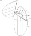
图10A是图9所示耳机组件的充电盒在另一使用状态中的结构示意图;Fig. 10A is a schematic structural view of the charging box of the earphone assembly shown in Fig. 9 in another use state;
图10B是图10A所示充电盒在另一角度的结构示意图;Fig. 10B is a structural schematic diagram of the charging box shown in Fig. 10A at another angle;
图11是图9所示充电盒的部分分解结构示意图;Fig. 11 is a schematic diagram of a partial exploded structure of the charging box shown in Fig. 9;
图12是图10A在C-C处的截面结构示意图;Fig. 12 is a schematic cross-sectional structure diagram at C-C of Fig. 10A;
图13是图10A在D-D处的截面结构示意图;Fig. 13 is a schematic diagram of a cross-sectional structure at D-D in Fig. 10A;
图14是图8所示耳机组件在另一角度的结构示意图;Fig. 14 is a structural schematic diagram of the earphone assembly shown in Fig. 8 at another angle;
图15是图11所示充电盒的部分结构示意图;Fig. 15 is a partial structural schematic diagram of the charging box shown in Fig. 11;
图16是图15中部分结构的组装结构示意图一;Fig. 16 is a schematic diagram of the assembled structure of part of the structure in Fig. 15;
图17是图15中部分结构的组装结构示意图二;Fig. 17 is a second schematic diagram of the assembly structure of the partial structure in Fig. 15;
图18是图13所示充电盒的部分结构示意图;Fig. 18 is a partial structural schematic diagram of the charging box shown in Fig. 13;
图19是图11所示充电盒的部分结构的分解结构示意图。FIG. 19 is an exploded schematic diagram of a partial structure of the charging box shown in FIG. 11 .
具体实施方式Detailed ways
下面将结合附图对本申请实施例中的技术方案进行描述。其中,在本申请实施例的描述中,除非另有说明,“/”表示或的意思,例如,A/B可以表示A或B;文本中的“和/或”仅仅是一种描述关联对象的关联关系,表示可以存在三种关系,例如,A和/或B,可以表示:单独存在A,同时存在A和B,单独存在B这三种情况,另外,在本申请实施例的描述中,“多个”是指两个或多于两个。The technical solutions in the embodiments of the present application will be described below with reference to the accompanying drawings. Among them, in the description of the embodiments of this application, unless otherwise specified, "/" means or means, for example, A/B can mean A or B; "and/or" in the text is only a description of associated objects The association relationship indicates that there may be three kinds of relationships, for example, A and/or B, which may indicate: A exists alone, A and B exist at the same time, and B exists alone. In addition, in the description of the embodiment of the present application , "plurality" means two or more than two.
以下,术语“第一”、“第二”等用词仅用于描述目的,而不能理解为暗示或暗示相对重要性或者隐含指明所指示的技术特征的数量。由此,限定有“第一”、“第二”的特征可以明示或者隐含地包括一个或者更多个该特征。Hereinafter, terms such as "first" and "second" are used for description purposes only, and cannot be understood as implying or implying relative importance or implicitly specifying the quantity of indicated technical features. Thus, a feature defined as "first" and "second" may explicitly or implicitly include one or more of these features.
本申请实施例中所提到的方位用语,例如,“前”、“后”、“左”、“右”、“内”、“外”、“侧面”、“顶”、“底”、“上”、“下”等,仅是参考附图的方向,因此,使用的方位用语是为了更好、更清楚地说明及理解本申请实施例,而不是指示或暗指所指的装置或元件必须具有特定的方位、以特定的方位构造和操作,因此不能理解为对本申请实施例的限制。The orientation terms mentioned in the embodiments of the present application, for example, "front", "rear", "left", "right", "inner", "outer", "side", "top", "bottom", "Up", "Down", etc. are only referring to the directions of the accompanying drawings. Therefore, the orientation terms used are for better and more clearly explaining and understanding the embodiments of the present application, rather than indicating or implying the referred device or Elements must have certain orientations, be constructed and operate in certain orientations, and therefore should not be construed as limitations on the embodiments of the present application.
在本申请实施例的描述中,需要说明的是,除非另有明确的规定和限定,术语“安装”、“相连”、“连接”、“设置在……上”应做广义理解,例如,“连接”可以是可拆卸地连接,也可以是不可拆卸地连接;可以是直接连接,也可以通过中间媒介间接连接。其中,“固定连接”是指彼此连接且连接后的相对位置关系不变。其中,“电连接”是指彼此之间可以导通电信号。In the description of the embodiments of this application, it should be noted that unless otherwise specified and limited, the terms "installation", "connection", "connection", and "set on ..." should be understood in a broad sense, for example, "Connection" may be detachable connection or non-detachable connection; it may be direct connection or indirect connection through an intermediary. Wherein, "fixed connection" means that they are connected to each other and the relative positional relationship after connection remains unchanged. Wherein, "electrically connected" means that electrical signals can be conducted with each other.
本申请提供一种耳机组件,耳机组件包括充电盒和耳机,充电盒用于收纳耳机。充电盒也可以称为充电仓或耳机盒。充电盒内含电池,能够对收纳在盒内的耳机充电,以满足用户长时间使用的需求。The present application provides an earphone assembly, the earphone assembly includes a charging box and an earphone, and the charging box is used to store the earphone. The charging case can also be called a charging case or a headphone case. The charging box contains batteries, which can charge the earphones stored in the box to meet the needs of users for long-term use.
关于耳机的整体造型及分型:About the overall shape and type of the earphone:
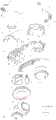
请结合参阅图1A、图1B以及图2,图1A是本申请提供的耳机10在一些实施例中的后视图,图1B是图1A所示耳机10的左视图,图2是图1A所示耳机10在一些使用场景中的结构示意图。Please refer to FIG. 1A, FIG. 1B and FIG. 2 in conjunction. FIG. 1A is a rear view of the
本申请提供一种耳机10,耳机10为无线耳机,例如可以为TWS(True WirelessStereo,真无线立体声耳机)耳机。为方便后文描述,定义耳机10具有相对的方位“顶”和方位“底”,对应于耳机10的高度方向;耳机10具有相对的方位“左”和方位“右”,对应于耳机10的宽度方向;耳机10具有相对的方位“前”和方位“后”,对应于耳机10的厚度方向。在一些实施例的描述中,方位“上”与方位“顶”对应,方位“下”与方位“底”对应。The present application provides an
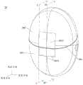
耳机10包括耳包10a和耳杆10b,耳杆10b也可以称为手柄,耳杆10b的顶部连接于耳包10a的后侧。耳机10的外表面是光滑过渡的几何曲面。耳杆10b在连接耳包10a的一端向远离耳包10a的一端的方向上,外轮廓整体呈现先收缩、后扩大、再收缩的形态,耳杆10b像是自由垂落的水滴那样圆润而自然。示例性的,耳机10可以具有中心面10c,耳包10a的中轴10d可以相对中心面10c倾斜。其中,当耳机10用作左耳机时,耳包10a的中轴10d的底端可以相对中心面10c向左偏转,耳包10a的中轴10d的顶端可以相对中心面10c向右偏转;当耳机10用作右耳机时,耳包10a的中轴10d的底端可以相对中心面10c向右偏转,耳包10a的中轴10d的顶端可以相对中心面10c向左偏转。示例性的,耳杆10b的外轮廓可以相对中心面10c对称设置。The
耳机10佩戴于消费者的耳部时,耳机10的前侧朝向耳部,耳机10的后侧背向耳部。耳机10的前侧多为不可见区域,耳机10的后侧多为可见区域。耳机10的耳包10a塞入耳部的耳甲腔,耳杆10b的顶部位于耳甲腔,耳杆10b的底部位于耳甲腔外。其中,耳部的耳屏、耳屏间切迹、对耳屏可以刚好环绕于耳杆10b的收缩部位,以通过夹持耳杆10b的收缩部分,在提高耳机10佩戴稳定,也能够兼顾佩戴舒适度,以提高用户的使用体验。When the
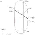
请结合参阅图3和图4,图3是图1A所示耳机10的部分分解结构示意图,图4是图1A所示耳机10沿A-A处剖开的截面结构示意图。其中,A-A处与耳机10的中心面10c对应。Please refer to FIG. 3 and FIG. 4 in conjunction. FIG. 3 is a schematic diagram of a partial exploded structure of the
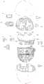
一些实施例中,耳机10包括壳体1及安装于壳体1内的多个组件,多个组件包括但不限于电路组件2、音频组件3、音频辅助组件4、检测组件5、天线6、第一触点71、第二触点72、电池73以及磁吸件81。In some embodiments, the
示例性的,电路组件2可以包括主电路板21、第一柔性电路板22以及第二柔性电路板23。各电路板上均可以固定有多个器件。例如,主电路板21上可以排布有主控芯片211,主控芯片211可以为系统级芯片(System on Chip,SOC)。主控芯片211可以集成多个电路。第一柔性电路板22的一端电连接主电路板21,第二柔性电路板23的一端电连接主电路板21,以实现各电路板上的器件间的电连接。电路组件2与耳机10的其他功能器件、模组等电连接。Exemplarily, the circuit assembly 2 may include a
示例性的,音频组件3可以包括扬声器31和多个麦克风,用于实现声音播放和声音拾取。扬声器31也可以称为“喇叭”,用于将音频电信号转换为声音信号。麦克风用于将声音信号转换为电信号,主要用来收集耳机10外部的声音,并将其转化为电信号传输给主控芯片211处理,以实现耳机10的主动降噪、语音通话、通话降噪、环境音模式、语音助手唤醒等功能。Exemplarily, the audio component 3 may include a
其中,多个麦克风可以包括第一麦克风32、第二麦克风33及第三麦克风34。在本申请中,耳机10的音频组件3的第一麦克风32和第二麦克风33应用于主动噪声消除(ActiveNoise Cancelling,ANC)设计系统中,主动噪声消除是一种将不需要的声源识别为噪声的方法,通过产生“抗噪声”信号来消除原始噪声,从而实时地消除噪声的设计。其中,第二麦克风33可以为FF(Feed Forward topology,前馈拓扑)麦克风,FF麦克风为面向用户耳外的参考麦克风,用于感知噪音主信号,可以作为前向主动噪声消除滤波器的参考信号。第一麦克风32可以为FB(Feed Back Topology,反馈拓扑)麦克风,FB麦克风为误差麦克风,用于收集进入用户耳中的信号,作为反馈主动噪声消除滤波器的参考信号。第三麦克风34可以为通话麦克风。Wherein, the plurality of microphones may include a
示例性的,音频辅助组件4用于提供多个通道,以辅助音频组件3实现声音播放、声音拾取等。音频辅助组件4可以包括第一组件41、第二组件42、第三组件43、第四组件44、第五组件45以及第六组件46,上述多个组件安装于壳体1的不同位置,用于为音频组件3的多个部件提供对应的通道。Exemplarily, the audio auxiliary component 4 is used to provide multiple channels to assist the audio component 3 to realize sound playback, sound pickup and the like. The audio auxiliary assembly 4 may include a
示例性的,检测组件5包括多个传感器,多个传感器可以包括接近传感器51、佩戴检测传感器52、霍尔传感器(hall sensor)(图中未示出)、触控传感器54、重力传感器(g-sensor)(图中未示出)等。其中,接近传感器51和佩戴检测传感器52用于实现耳机10的佩戴检测;霍尔传感器用于实现耳机10入盒检测;触控传感器54用于检测用户的触摸动作,重力传感器用于检测耳机10的姿态变化,触控传感器54和重力传感器用于提升耳机10的人机交互体验。其中,佩戴检测传感器52和触控传感器54可以为电容传感器(Cap-sensor)。其中,检测组件5可以包括检测电路板56,检测电路板56形成上述佩戴检测传感器52和触控传感器54。Exemplarily, the detection component 5 includes a plurality of sensors, and the plurality of sensors may include a
其中,一些使用场景中,耳机10通过佩戴检测功能,可以判断用户是否佩戴/摘下耳机10,以自动播放/暂停播放音乐。另一些使用场景中,如果用户摘下耳机10长时间未佩戴并且没有放回充电盒,耳机10会自动休眠/关机,以节省电量。另一些使用场景中,为提升耳机10的单/双耳使用的体验,两只耳机10佩戴时,两只耳机10均播放音乐,在一只耳机10摘下、另一只耳机10佩戴时,处于非佩戴状态的耳机10停止播放音乐,处于佩戴状态的耳机10继续播放,实现无缝切换。Wherein, in some usage scenarios, the
其中,一些使用场景中,耳机10通过人机交互功能可以检测用户不同的触摸动作或操作动作,实现耳机10的音乐的播放/暂停、上下曲切换、音量大小调节、智能语音唤醒等功能,使得耳机10在使用时可以一定程度上脱离其连接的终端(手机、平板等),操作更为方便、快捷,有利于提高用户使用体验。Among them, in some use scenarios, the
示例性的,天线6用于实现耳机10与其他终端(例如手机、平板等)的无线通信。电池73用于为耳机10供电。第一触点71和第二触点72用于在耳机10收纳于充电盒内时,实现与充电盒之间的通信,以及充电盒对耳机10的充电过程。磁吸件81用于在耳机10入盒时,与充电盒之间形成磁吸力,以使耳机10稳定放置于充电盒内。Exemplarily, the antenna 6 is used to implement wireless communication between the
在本申请另一些实施例中,耳机10可以包括比上述实施例更多或更少的部件,或者组合某些部件,或者拆分某些部件,或者不同的部件布置。耳机10的各部件可以以硬件、软件或软件和硬件的组合实现。In other embodiments of the present application, the
请参阅图5,图5是图1A所示耳机10的部分电路的示意框图。Please refer to FIG. 5 , which is a schematic block diagram of some circuits of the
一些实施例中,耳机10可以包括处理器2a、存储器2b、音频处理电路2c、射频电路2d、射频前端2e、电源管理电路2f、充电电路2g等。处理器2a电连接存储器2b。In some embodiments, the
其中,扬声器31、第一麦克风32、第二麦克风33及第三麦克风34均电连接音频处理电路2c,音频处理电路2c电连接处理器2a。音频处理电路2c用于将数字音频信息转换成模拟音频信号输出,也用于将模拟音频输入转换为数字音频信号。音频处理电路2c还可以用于对音频信号编码和解码。在一些实施例中,音频处理电路2c也可以设置于处理器2a中,或将音频处理电路2c的部分功能模块设置于处理器2a中。Wherein, the
其中,天线6连接射频前端2e,射频前端2e连接射频电路2d,射频电路2d连接处理器2a。射频电路2d用于调制射频信号或解调射频信号,射频前端2e用于对射频信号进行过滤和放大。其中,射频前端2e可以包括功率放大器(Power Amplifier,PA)、滤波器、开关(Switch)、低噪音放大器(LNA,Low Noise Amplifier)中的一者或多者。其中,滤波器可以是声表面波滤波器(surface acoustic wave,SAW)。Wherein, the antenna 6 is connected to the radio frequency
其中,第一触点71和第二触点72电连接充电电路2g,充电电路2g电连接处理器2a、电源管理电路2f以及电池73。充电电路2g用于通过第一触点71和第二触点72接收充电输入。电源管理电路2f电连接处理器2a。电源管理电路2f接收电池73和/或充电电路2g的输入,为处理器2a、存储器2b及其他部件供电。在其他一些实施例中,电源管理电路2f也可以设置于处理器2a中。在另一些实施例中,电源管理电路2f和充电电路2g也可以设置于同一个器件中。Wherein, the
其中,接近传感器51、佩戴检测传感器52、霍尔传感器53、触控传感器54、重力传感器55均电连接处理器2a。Wherein, the
其中,处理器2a、存储器2b、音频处理电路2c、射频电路2d、电源管理电路2f可以集成于主控芯片211中。射频前端2e和充电电路2g可以分别形成于其他芯片中。在其他一些实施例中,上述电路也可以有其他实现结构,例如,主控芯片211可以集成更多或更少的电路,例如射频电路2d可以独立在主控芯片211之外,由射频芯片实现,本申请实施例对此不做严格限定。Wherein, the
关于耳机10的壳体1:About the
请结合参阅图1A、图1B、图6以及图7,图6是图3所示壳体1的分解结构示意图,图7是图3所示壳体1的内部结构示意图。Please refer to FIG. 1A , FIG. 1B , FIG. 6 and FIG. 7 . FIG. 6 is a schematic diagram of an exploded structure of the
一些实施例中,壳体1包括主壳11和前壳12,前壳12固定于主壳11的前侧,前壳12的内部空间121与主壳11的内部空间111连通。耳机10处于佩戴状态时,前壳12朝向用户耳部,具体的,前壳12可以位于耳甲腔、接触耳甲腔,并朝向用户耳部的耳道。前壳12和主壳11的连接前壳12的部分结构形成耳机10的耳包10a的外壳,主壳11的另一部分结构形成耳机10的耳杆10b的外壳。In some embodiments, the
其中,主壳11包括第一端11a和第二端11b,主壳11的第一端11a靠近前壳12并接触前壳12,主壳11的第二端11b远离前壳12。主壳11具有脊背线112,脊背线112自主壳11的第一端11a延伸至主壳11的第二端11b。其中,脊背线112位于主壳11的后侧,脊背线112位于耳机10的中心面10c上。脊背线112为平滑的曲线。其中,如图1B所示,耳机10处于左视视角中时,主壳11的朝后一侧(也即背向前壳12一侧)的轮廓线对应于脊背线112。其中,脊背线112可以为实体线条,也可以为非实体线条,本申请实施例对此不作严格限定。Wherein, the
示例性的,在主壳11的第一端11a向主壳11的第二端11b的方向上,主壳11的外轮廓先收缩、后扩大。其中,主壳11的外轮廓先收缩、后扩大的情况包括:第一种情况是主壳11的外轮廓先收缩、后扩大、再收缩,第二种情况是主壳11的外轮廓先收缩、后扩大。Exemplarily, in the direction from the
其中,对于第一种情况:在主壳11的第一端11a向主壳11的第二端11b的方向上,主壳11位于耳包10a的部分呈收缩形态,主壳11位于耳杆10b的部分呈现先收缩、后扩大、再收缩的形态,主壳11的底部可以由弧面或近似弧面形成底部端面,以具有圆润的形态。此时,主壳11的形状设计使得耳机10的耳杆10b能够具有与“自由垂落的水滴”近似的形状。Among them, for the first case: in the direction from the
对于第二种情况:在主壳11的第一端11a向主壳11的第二端11b的方向上,主壳11位于耳包10a的部分呈收缩形态,主壳11位于耳杆10b的部分呈现先收缩、后扩大,也即主壳11的底部可以由平面或近似平面形成底部端面。在第二种情况中,主壳11的底部可能存在与底部端面连接的小圆角过渡区域,这部分过渡区域的形态变化很小,可以忽略。For the second case: in the direction from the
示例性的,如图7所示,主壳11的内部空间111包括依次连通的顶部空间111a、中部空间111b及底部空间111c,主壳11的顶部空间111a靠近主壳11的第一端11a,主壳11的底部空间111c靠近主壳11的第二端11b。主壳11的顶部空间111a连接前壳12的内部空间121。在主壳11的第一端11a向主壳11的第二端11b的方向上,主壳11的内部空间111先收缩、后扩大。主壳11的顶部空间111a的截面积基本大于主壳11的中部空间111b的截面积,主壳11的底部空间111c的截面积基本大于主壳11的中部空间111b的截面积。也即,主壳11的内部空间111中最窄的位置处于主壳11的中部空间111b中。在本实施例中,主壳11为壳件结构,主壳11的内部空间111的形态变化与主壳11的外轮廓的形态变化是相同或相近的。Exemplarily, as shown in FIG. 7, the
可以理解的是,本申请实施例的附图中对主壳11的顶部空间111a、中部空间111b及底部空间111c的划分位置为示例性位置,并非严格的、唯一的位置划分,耳机10在整体设计上满足主壳11的内部空间111于其中部空间111b收缩到最窄即可,主壳11的顶部空间111a、中部空间111b及底部空间111c的划分位置可以根据实际情况发生适应性变化。It can be understood that the division positions of the
示例性的,脊背线112由主壳11的第一端11a向主壳11的第二端11b延伸时,脊背线112先向后延伸,后向前延伸。其中,主壳11的与脊背线112向后延伸的线段对应的部分,呈现先收缩、后扩大的形态;主壳11的与脊背线112向前延伸的线段对应的部分,呈现收缩形态。在本实施例中,通过设置脊背线112的形状,使得耳机10的背部呈现自由滑落的形态,耳机10的整体形态自然、美观。Exemplarily, when the
其中,脊背线112可以包括多个平滑连接的弧线段,在脊背线112的延伸方向上,多个弧线段的半径先增加后减小。其中,半径最大的弧线段可以对应主壳11的中部空间111b设置。Wherein, the
一些实施例中,如图1B、图6以及图7所示,主壳11包括主壳件113和封盖件114。主壳件113具有间隔设置的第一开口1131和第二开口1132,第一开口1131和第二开口1132均朝前设置。也即,耳机10处于佩戴状态时,第一开口1131和第二开口1132均朝向用户耳部。主壳件113包括依次连接的顶部113a、中部113b及底部113c,第一开口1131形成于主壳件113的顶部113a,第二开口1132形成于主壳件113的底部113c。前壳12安装于第一开口1131,封盖件114安装于第二开口1132,封盖件114位于主壳件113的底部113c的前侧。其中,如图7所示,主壳件113的顶部113a的内侧空间形成主壳11的顶部空间111a,主壳件113的中部113b的内侧空间形成主壳11的中部空间111b,封盖件114与部分主壳件113(也即主壳件113的底部113c)共同围设出主壳11的底部空间111c。其中,主壳件113可以为一体成型的结构件,例如主壳件113可以通过注塑工艺成型。In some embodiments, as shown in FIG. 1B , FIG. 6 and FIG. 7 , the
在本实施例中,壳体1由前壳12、主壳件113及封盖件114这三个主要壳件构成,数量少,结构简单,易于组装。此外,主壳件113的中部113b为完整壳件结构,未设置开口,有利于提高主壳件113的结构强度,使得主壳11及壳体1的整体结构强度较高。In this embodiment, the
示例性的,结合参阅图1A、图6以及图7,主壳11包括抵接端面113d,抵接端面113d位于主壳件113且环绕第一开口1131设置,抵接端面113d接触前壳12。抵接端面113d所在平面垂直于耳机10的中心面10c。主壳件113在抵接端面113d所在平面上具有第一投影,封盖件114在抵接端面113d所在平面上具有第二投影,第一投影覆盖第二投影。Exemplarily, referring to FIG. 1A , FIG. 6 and FIG. 7 , the
其中,耳机10在后视视角中的表面为主要外观面,也即由后向前看,耳机10露出的表面为主要外观面;耳机10在前视视角中的表面为次要外观面,也即由前向后看,耳机10露出的表面为主要外观面;耳机10处于佩戴状态时,次要外观面面向用户耳部、而被隐藏,主要外观面背向用户耳部,而露出。主壳件113由后向前投影形成第一投影,封盖件114由后向前投影形成第二投影,由于第一投影覆盖第二投影,在耳机10的后视视角中,主壳件113遮挡封盖件114,耳机10将封盖件114与主壳件113的分型线隐藏在次要外观面,使得耳机10的主要外观面完整,保持了良好的视觉整体感。封盖件114与主壳件113的分型线为封盖件114与主壳件113交接处于耳机10的外观面上形成的线。其中,主壳件113在左右方向上的最大轮廓线如图1B中虚线所示,封盖件114与主壳件113的分型线位于该最大轮廓线的前侧。Wherein, the surface of the
在一些实施例中,耳机10的整体高度可以在35mm至45mm的范围内,例如38mm、39.56mm、41.5mm、43.21mm等;耳机10的整体宽度可以在19mm至26mm的范围内,例如21mm、22.83mm、24.5mm等。主壳件113的整体高度可以在35mm至45mm的范围内,例如37mm、39.38mm、41.2mm、42.8mm等。主壳件113的底部113c的最厚处的厚度可以在8mm至12mm的范围内,例如8.2mm、9mm、9.74mm、10.11mm、10.53mm等;主壳件113的底部113c的最宽处的宽度可以在11mm至16mm的范围内,例如12mm、12.8mm、13.53mm、14.2mm等。主壳件113在前后方向上最窄的位置处的厚度可以在6mm至8.5mm的范围内,例如6.5mm、7.2mm、7.4mm等;主壳件113在左右方向上最窄的位置处的宽度在5mm至8.5mm的范围内,例如6.47mm。封盖件114与前壳12在前后间距可以在5mm至8mm的范围内,例如5.7mm、6mm、6.54mm、7.12mm等。耳包10a的中轴10d与中心面10c的夹角可以在50°至70°的范围内,例如55°、60°、67°等。耳包10a与耳杆10b的分界线与主壳件113的抵接端面113d的夹角可以在7°至10°的范围内,例如7.6°、8.4°、9.2°等。在其他一些实施例中,耳机10的上述尺寸中一者或多者也可以依据需要进行调整。In some embodiments, the overall height of the
可以理解的是,前文关于壳体1的结构描述只为示例性描述,在其他一些实施例中,壳体1也可以具有其他结构,本申请对此不做严格限定。It can be understood that the foregoing structural description about the
在上述实施例中,耳机10具有极致的空间利用率且匹配全新的外观造型,不仅能满足用户对产品的精致化、佩戴舒适性、全新的外观造型的需求;同时还能够满足用户对无线耳机10本身的音质、降噪及续航的需求。In the above embodiment, the
关于充电盒:About the charging case:
传统的充电盒的上、下盖采用比较规则的水平展示面,耳机垂直放置在充电盒内,耳机从充电盒取出的过程受耳机露出高度、耳机磁吸力、耳机形态的影响,成为用户使用过程中的一大痛点;例如,为满足耳机入盒的磁吸力要求,耳机与充电盒之间需要满足一定的磁吸力要求,耳机拿取便捷性受到严重影响,用户体验差;而为了提升耳机拿取的便捷性,常常需要产线严格管控磁吸力大小,增加了耳机组件的成本。此外,传统耳机组件中,耳机露出充电盒部分过少,用户可拿捏的区域小,也导致了用户拿取耳机困难。The upper and lower covers of the traditional charging box adopt relatively regular horizontal display surfaces, and the earphones are placed vertically in the charging box. The process of removing the earphones from the charging box is affected by the height of the earphones exposed, the magnetic force of the earphones, and the shape of the earphones. It is a major pain point; for example, in order to meet the magnetic attraction requirements of the earphones into the box, a certain magnetic attraction requirement must be met between the earphones and the charging box, which will seriously affect the convenience of taking the earphones and poor user experience; The convenience of picking often requires the production line to strictly control the size of the magnetic attraction, which increases the cost of the earphone assembly. In addition, in the traditional earphone assembly, the part of the earphone exposed to the charging box is too small, and the area that the user can handle is small, which also makes it difficult for the user to hold the earphone.
请结合参阅图8、图9、图10A及图10B,图8是本申请实施例提供一种耳机组件100在一些实施例中的结构示意图,图9是图8所示耳机组件100在另一使用状态中的结构示意图,图10A是图9所示耳机组件100的充电盒20在另一使用状态中的结构示意图,图10B是图10A所示充电盒20在另一角度的结构示意图。Please refer to FIG. 8 , FIG. 9 , FIG. 10A and FIG. 10B in conjunction. FIG. 8 is a structural schematic diagram of an
一些实施例中,耳机组件100包括充电盒20、第一耳机10’以及第二耳机10”,充电盒20具有间隔设置的第一耳机槽20a和第二耳机槽20b,第一耳机槽20a和第二耳机槽20b用于收容耳机。其中,第一耳机10’能够可拆卸地容置于第一耳机槽20a,第二耳机10”能够可拆卸地容置于第二耳机槽20b。第一耳机10’和第二耳机10”中的一者为左耳机,另一者为右耳机。本实施例中,以第一耳机10’为左耳机,第二耳机10”为右耳机为例,进行举例说明。在其他一些实施例中,第一耳机10’和第二耳机10”可以互换。其中,第一耳机10’和第二耳机10”均采用前文实施例中耳机的全部结构或大部分结构。In some embodiments, the
其中,第一耳机10’的壳体1’与第二耳机10”的壳体1”为互相对称结构,第一耳机槽20a与第二耳机槽20b为互相对称结构。其中,第一耳机10’的壳体1’本身为非对称结构,第一耳机槽20a本身为非对称结构,第一耳机槽20a的形状与第一耳机10’的壳体1’的形状相同。第二耳机10”的壳体1”本身为非对称结构,第二耳机槽20b本身为非对称结构,第二耳机槽20b的形状与第二耳机10”的壳体1”的形状相同。简言之,第一耳机槽20a与第一耳机10’适配,第二耳机槽20b与第二耳机10”适配。一些示例中,当第一耳机10’装入第一耳机槽20a、第二耳机10”装入第二耳机槽20b中时,两个耳机放置正确,充电盒20可以闭合;当第一耳机10’装入第二耳机槽20b、第二耳机10”装入第一耳机槽20a中时,两个耳机放置错误,充电盒20不能闭合。Wherein, the casing 1' of the first earphone 10' and the
示例性的,充电盒20具有相互垂直的宽度方向、厚度方向及高度方向,第一耳机槽20a和第二耳机槽20b排布于充电盒20的宽度方向,充电盒20在高度方向上的尺寸大于充电盒20在厚度方向上的尺寸。其中,充电盒20包括盒体201和盒盖202,盒盖202转动连接盒体201。Exemplarily, the
示例性的,如图10B所示,盒体201具有相对设置的第一端201a和第二端201b,盒盖202具有相对设置的第一端202a和第二端202b,盒盖202的第一端202a转动连接盒体201的第一端201a,且转动中心平行于充电盒20的宽度方向。盒盖202的第二端202b远离盒体201的第二端201b,以相对盒体201打开,或者,盒盖202的第二端202b靠近盒体201的第二端201b,以相对盒体201闭合。盒体201的第一端201a高于盒体201的第二端201b,换言之,在充电盒20的高度方向上,盒体201的第一端201a的尺寸大于盒体201的第二端201b的尺寸。此时,盒体201的顶部整体倾斜。Exemplarily, as shown in FIG. 10B , the
请结合参阅图9和图11,图11是图9所示充电盒20的部分分解结构示意图。Please refer to FIG. 9 and FIG. 11 in conjunction. FIG. 11 is a schematic diagram of a partially exploded structure of the
一些实施例中,盒体201包括盒体外壳2011和盒体内衬2012,盒体内衬2012固定于盒体外壳2011的内侧。盒盖202包括盒盖外壳2021和盒盖内衬2022,盒盖内衬2022固定于盒盖外壳2021的内侧。第一耳机槽20a和第二耳机槽20b均部分形成于盒体内衬2012,部分形成于盒盖内衬2022。In some embodiments, the
其中,请再次参阅图9至图10B,盒体201包括朝向盒盖202的顶面,盒体201的顶面包括盒体外壳2011的顶面2011a和盒体内衬2012的顶面2012a。盒盖202包括朝向盒体201的底面,盒盖202的底面包括盒盖外壳2021的底面2021a和盒盖内衬2022的底面。充电盒20闭合时,盒体201的顶面与盒盖202的底面相对,盒体外壳2011的顶面2011a与盒盖外壳2021的底面2021a相对,盒体内衬2012的顶面2012a和盒盖内衬2022的底面相对。9 to 10B again, the
其中,盒体外壳2011的顶面2011a与盒盖外壳2021的底面2021a的相接可以由充电盒20的外部看到,形成充电盒20的分型面20c,换言之,充电盒20的分型面20c包括盒体外壳2011的顶面2011a与盒盖外壳2021的底面2021a。其中,充电盒20的分型面20c相对充电盒20的厚度方向倾斜且相对充电盒20的高度方向倾斜。Wherein, the connection between the
其中,盒体外壳2011的顶面2011a可以为平面,盒盖外壳2021的底面2021a可以为平面,以降低盒体外壳2011和盒盖外壳2021的加工难度,也使得盒体外壳2011与盒盖外壳2021容易闭合,充电盒20的分型面20c呈平面,充电盒20的外观精致、简洁。在其他一些实施例中,充电盒20的分型面也可以为曲面,本申请实施例对此不作严格限定。Wherein, the
其中,当充电盒20打开时,第一耳机10’和第二耳机10”放置于盒体内衬2012,第一耳机10’和第二耳机10”相对盒体内衬2012的顶面2012a露出,盒体内衬2012的顶面2012a形成充电盒20的展示面。Wherein, when the
请结合参阅图9、图11以及图12,图12是图10A在C-C处的截面结构示意图。其中,为了便于示意,图12所处视角均相对图10A所处视角进行了转动。Please refer to FIG. 9 , FIG. 11 and FIG. 12 in conjunction. FIG. 12 is a schematic cross-sectional structure diagram at C-C of FIG. 10A . Wherein, for ease of illustration, the viewing angles in FIG. 12 are rotated relative to the viewing angles in FIG. 10A .
一些实施例中,第一耳机槽20a包括第一顶槽2013、第一底槽2014及第一配合槽2023,第一顶槽2013和第一底槽2014形成于盒体内衬2012,第一配合槽2023形成于盒盖内衬2022。如图12所示,充电盒20闭合时,第一顶槽2013、第一底槽2014及第一配合槽2023共同形成第一耳机槽20a,第一耳机槽20a的形状与第一耳机10’的形状适配。In some embodiments, the
其中,如图9和图12所示,第一顶槽2013相对第一底槽2014靠近盒体201的第一端201a,第一顶槽2013的槽深小于第一底槽2014的槽深,第一顶槽2013用于放置第一耳机10’的耳包10a’,第一底槽2014用于容置第一耳机10’的耳杆10b”。在第一耳机10’中,壳体1’的主壳11’包括靠近前壳12’的第一部分和远离前壳12’的第二部分,前壳12’和主壳11’的第一部分形成第一耳机10’的耳包10a’,主壳11’的第二部分形成第一耳机10’的耳杆10b”。Wherein, as shown in Figure 9 and Figure 12, the first
其中,第一顶槽2013的开口和第一底槽2014的开口均位于盒体内衬2012的顶面,并且第一底槽2014的开口低于第一顶槽2013的开口。其中,第一顶槽2013的开口的最低边缘不低于第一底槽2014的开口的最高边缘。此时,充电盒20的展示面为倾斜面,当第一耳机10’放置于第一耳机槽20a时,第一耳机10’相对充电盒20露出的部分较多,从而能够便于用户拿取,提高了提升用户从充电盒20中拿取耳机的使用体验,同时也保证了一定的美观性,提升了产品的外观精致度。Wherein, the opening of the first
其中,第一顶槽2013的开口可以与第一底槽2014的开口间隔设置。此时,第一底槽2014的开口靠近第一顶槽2013的开口的一端,低于第一顶槽2013的开口的靠近第一底槽2014的开口的一端。在本实施例中,第一底槽2014的开口可以较大幅度地低于第一顶槽2013的开口,使得第一耳机10’放置于第一耳机槽20a时,第一耳机10’相对充电盒20露出的部分更多。Wherein, the opening of the first
其中,第一顶槽2013的底壁的最低处不低于第一底槽2014的开口的最低边缘。在本实施例中,第一耳机10’放置于第一耳机槽20a时,第一耳机10’相对充电盒20露出的部分更多。Wherein, the lowest point of the bottom wall of the first
示例性的,第一耳机10’放置于第一耳机槽20a时,主壳11’的主壳件的底部位于第一底槽2014中,前壳12’和主壳件的顶部均部分位于第一顶槽2013中、部分位于盒体201的外部,主壳件的中部位于盒体201的外部。其中,主壳11’的主壳件的结构示意图和描述可以参考前文耳机10的主壳件113的相关内容。Exemplarily, when the first earphone 10' is placed in the
同样的,第二耳机槽20b包括第二顶槽2015、第二底槽2016及第二配合槽2024,第二顶槽2015和第二底槽2016形成于盒体内衬2012,第二配合槽2024形成于盒盖内衬2022。充电盒20闭合时,第二顶槽2015、第二底槽2016及第二配合槽2024共同形成第二耳机槽20b,第二耳机槽20b的形状与第二耳机10”的形状适配。Similarly, the
其中,第二顶槽2015相对第二底槽2016靠近盒体201的第一端201a,第二顶槽2015的槽深小于第二底槽2016的槽深,第二顶槽2015用于放置第二耳机10”的耳包10a”,第二底槽2016用于容置第二耳机10”的耳杆10b”。在第二耳机10”中,主壳11”包括靠近前壳12”的第一部分和远离前壳12”的第二部分,前壳12”和主壳11”的第一部分形成第二耳机10”的耳包10a”,主壳11”的第二部分形成第二耳机10”的耳杆10b”。Wherein, the second
其中,第二顶槽2015的开口和第二底槽2016的开口均位于盒体内衬2012的顶面,并且第二底槽2016的开口低于第二顶槽2015的开口。其中,第二顶槽2015的开口的最低边缘不低于第二底槽2016的开口的最高边缘。此时,充电盒20的展示面为倾斜面,第二耳机10”放置于第二耳机槽20b时,第二耳机10”相对充电盒20露出的部分较多,从而能够便于用户拿取,提高了提升用户从充电盒20中拿取耳机的使用体验,同时也保证了一定的美观性,提升了产品的外观精致度。Wherein, the opening of the second
其中,第二顶槽2015的开口可以与第二底槽2016的开口间隔设置。此时,第二底槽2016的开口靠近第二顶槽2015的开口的一端,低于第二顶槽2015的开口的靠近第二底槽2016的开口的一端。在本实施例中,第二底槽2016的开口可以较大幅度地低于第二顶槽2015的开口,使得第二耳机10”放置于第二耳机槽20b时,第二耳机10”相对充电盒20露出的部分更多。Wherein, the opening of the second
其中,第二顶槽2015的底壁的最低处不低于第二底槽2016的开口的最低边缘。在本实施例中,第二耳机10”放置于第二耳机槽20b时,第二耳机10”相对充电盒20露出的部分更多。Wherein, the lowest point of the bottom wall of the second
示例性的,第二耳机10”放置于第二耳机槽20b时,主壳11”的主壳件的底部位于第二底槽2016中,前壳12”和主壳件的顶部均部分位于第二顶槽2015中、部分位于盒体201的外部,主壳件的中部位于盒体201的外部。其中,主壳11”的主壳件的结构示意图和描述可以参考前文耳机10的主壳件113的相关内容。Exemplarily, when the
示例性的,盒体内衬2012的顶部可以相对盒体外壳2011凸起,也即盒体外壳2011的顶面2011a相对盒体内衬2012的顶面2012a。此时,用户能够更为便捷地拿取放置于充电盒20中的耳机,提高了用户体验。Exemplarily, the top of the box
其中,盒体外壳2011的顶面2011a可以为曲面,以使第一顶槽2013的开口和第一底槽2014的开口的形状更好地匹配和支撑第一耳机10’,第二顶槽2015的开口可以与第二底槽2016的开口的形状更好地匹配和支撑第二耳机10”,此时,两个耳机于充电盒20中的放置稳定可靠,同时也便于用户拿取,此外,也使得充电盒20的展示面美观、精致。在其他一些实施例中,盒体外壳2011的顶面2011a也可以为平面,本申请实施例对此不作严格限定。Wherein, the
请结合参阅图11至图14,图13是图10A在D-D处的截面结构示意图,图14是图8所示耳机组件100在另一角度的结构示意图。其中,为了便于示意,图13所处视角均相对图10A所处视角进行了转动。Please refer to FIG. 11 to FIG. 14 in conjunction. FIG. 13 is a schematic cross-sectional view at D-D of FIG. 10A , and FIG. 14 is a schematic structural view of the
一些实施例中,如图11和图13所示,充电盒20还包括转轴组件203和装饰件204。其中,转轴组件203安装于盒体201,盒盖202可以通过转轴组件203转动连接盒体201。装饰件204安装于转轴组件203的外侧,用于遮盖和装饰转轴组件203,以提高充电盒20的外观精致度。In some embodiments, as shown in FIG. 11 and FIG. 13 , the
一些实施例中,如图11和图12所示,充电盒20还包括磁吸组件205,磁吸组件205包括第一磁铁2051、第二磁铁2052、第三磁铁2053以及第四磁铁2054。In some embodiments, as shown in FIG. 11 and FIG. 12 , the
其中,第一磁铁2051固定于盒体内衬2012,第一磁铁2051位于盒体内衬2012的顶面的下方,且位于第一顶槽2013与第一底槽2014之间。在本实施例中,第一顶槽2013与第一底槽2014之间有较大的空间,从而能够放置体积较大的第一磁铁2051,以增加用于吸引第一耳机10’的磁吸力。如图14所示,第一耳机10’置于第一耳机槽20a时,第一耳机10’的磁吸件81’与充电盒20的第一磁铁2051相对设置,两者靠近且间距较小,从而产生足够的磁吸力,使得第一耳机10’稳定地放置于充电盒20内。Wherein, the
其中,第二磁铁2052固定于盒体内衬2012,第二磁铁2052位于盒体内衬2012的顶面的下方,且位于第二顶槽2015与第二底槽2016之间。第二耳机10”置于第二耳机槽20b时,第二耳机10”的磁吸件与充电盒20的第二磁铁2052相对设置,两者靠近且间距较小。Wherein, the
如图9和图13所示,第三磁铁2053固定于盒盖内衬2022,第三磁铁2053位于盒盖内衬2022与盒盖外壳2021之间,第三磁铁2053位于盒盖202的第二端202b的中部位置,且靠近盒盖202的底部设置。As shown in Figure 9 and Figure 13, the
结合参阅图9、图10A以及图11,第四磁铁2054的数量可以为两个。第四磁铁2054固定于盒体内衬2012,位于盒体内衬2012与盒体外壳2011之间。第四磁铁2054位于盒体201的第二端201b的中部位置,且靠近盒体201的顶部设置。当充电盒20闭合时,第三磁铁2053与第四磁铁2054之间产生磁吸力,以使充电盒20闭合稳定。Referring to FIG. 9 , FIG. 10A and FIG. 11 in conjunction, the number of
关于充电盒20的转轴组件203和装饰件204:About the
请结合参阅图15至图18,图15是图11所示充电盒20的部分结构示意图,图16是图15中部分结构的组装结构示意图一,图17是图15中部分结构的组装结构示意图二,图18是图13所示充电盒20的部分结构示意图。其中,为了便于示意,图17所处视角相对图13视角进行了转动。Please refer to FIG. 15 to FIG. 18 in conjunction. FIG. 15 is a schematic diagram of a part of the structure of the
一些实施例中,转轴组件203可以包括转轴2031、转轴支架2032及扭转弹簧2033。其中,转轴支架2032固定于盒体201,盒盖202通过转轴2031转动连接转轴支架2032,以转动连接盒体201。具体的,盒体内衬2012设有安装槽2017,转轴支架2032安装于安装槽2017中,以固定连接盒体内衬2012。转轴2031插接转轴支架2032,转轴2031还插接盒盖202。In some embodiments, the
其中,转轴支架2032可以包括主体2032a、第一支臂2032b、第二支臂2032c及卡位块2032d,主体2032a内侧形成活动空间2032e,第一支臂2032b和第二支臂2032c分别固定于主体2032a的两端且位于活动空间2032e的两侧,第一支臂2032b和第二支臂2032c均设有转轴孔,卡位块2032d位于活动空间2032e内且固定于主体2032a。转轴2031的一端插接第一支臂2032b的转轴孔,另一端穿过活动空间2032e后,插接第二支臂2032c的转轴孔。Wherein, the
其中,盒盖202还可以包括转接块2025,转接块2025可以固定于盒盖外壳2021。转接块2025通过转轴2031转动连接转轴支架2032,转轴2031插接转接块2025。其中,转接块2025设有转轴孔2025a和卡接孔2025b。其中,转轴孔2025a与卡接孔2025b间隔设置,卡接孔2025b位于转轴孔2025a的远离盒盖外壳2021的一侧。转接块2025位于转轴支架2032的活动空间2032e,转轴2031穿过转接块2025的转轴孔2025a。Wherein, the
其中,扭转弹簧2033位于转轴支架2032的活动空间2032e,扭转弹簧2033的一端连接转轴支架2032,扭转弹簧2033的另一端连接转接块2025。例如,扭转弹簧2033的一端可以抵接或卡接转轴支架2032的卡位块2032d,扭转弹簧2033的另一端可以插入转接块2025的卡接孔。在本实施例中,扭转弹簧2033的设置使得充电盒20具有开关盖的手感。Wherein, the
示例性的,装饰件204包括第一板件2041、第二板件2042及第三板件2043,第二板件2042及第三板件2043分别连接于第一板件2041的两端,且均相对第一板件2041弯折。第二板件2042和第三板件2043均设有转轴孔。第一板件2041位于转接块2025的外侧,且覆盖转接块2025的外侧面;第二板件2042位于转接块2025与转轴支架2032的第一支臂2032b之间,第三板件2043位于转接块2025与转轴支架2032的第二支臂2032c之间,转轴2031插入第二板件2042的转轴孔和第三板件2043的转轴孔,以插接第二板件2042和第三板件2043。Exemplarily, the
其中,如图18所示,盒体201设有缺口2018,缺口2018可以形成于盒体外壳2011,缺口2018对应盒盖202的转接块2025设置,以为转接块2025提供活动空间。其中,盒盖202相对盒体201闭合时,转接块2025位于分型面20c靠近盒体201的一侧,并覆盖缺口2018。盒体201遮挡部分转轴组件203,装饰件204遮挡另一部分转轴组件203,使得充电盒20的外观完整。Wherein, as shown in FIG. 18 , the
在本实施例中,装饰件204遮盖转接块2025的外侧面,充电盒20闭合时,装饰件204覆盖盒体201的缺口2018,与盒体201共同形成充电盒20的外观。由于装饰件204设计了两端穿轴的结构,解决了传统的后贴装饰件、装饰件与盒体之间的间隙不均匀的问题,提高了美观度,同时也增加了对转轴2031的支撑,使得转轴组件203的结构强度较高,提高了可靠性。In this embodiment, the
请结合参阅图13和图15,一些实施例中,充电盒20还包括无线充电线圈2061和电池2062,无线充电线圈2061和电池2062均固定于盒体201内,且位于转轴组件203的下方。充电盒20可以通过无线充电线圈2061对电池2062进行充电。Please refer to FIG. 13 and FIG. 15 . In some embodiments, the
示例性的,转轴支架2032可以包括金属部分20321和塑胶部分20322,金属部分20321与塑胶部分20322相互固定,转轴2031插接金属部分20321。也即,第一支臂2032b的转轴孔及第二支臂2032c的转轴孔均形成于金属部分20321。金属部分20321可以采用不锈钢等金属材料。其中,转轴支架2032可以为一体成型的结构件,以具有较高的结构强度。例如,转轴支架2032可以通过金属注射成型(Metal injection Molding,MIM)工艺、金属嵌件注塑等工艺成型。其中,塑胶部分20322位于金属部分20321与无线充电线圈2061之间。Exemplarily, the
在本实施例中,转轴支架2032可以在保证连接结构强度的同时,降低金属件对充电盒20在无线充电过程中的不良影响,以确保耳机组件100的无线充电性能。In this embodiment, the
示例性的,装饰件204可以采用铝合金材料。此时,装饰件204美观且结构强度较高,同时还能够降低对充电盒20的无线充电过程的影响。其中,装饰件204可以通过板件弯折形成,结构强度高,易加工,成本低。Exemplarily, the
请结合参阅图12、图13以及图19,图19是图11所示充电盒20的部分结构的分解结构示意图。Please refer to FIG. 12 , FIG. 13 and FIG. 19 in conjunction. FIG. 19 is an exploded schematic diagram of a partial structure of the
一些实施例中,充电盒20还包括安装在盒体外壳2011与盒体内衬2012之间的多个部件,多个部件可以包括第一壳件2071、第二壳件2072、第三壳件2073、电路板2081、连接电路板2082、电极组件209、霍尔传感器2010、指示灯2020、按键组件2030、电连接器2040、无线充电组件2050、电池2062及多个紧固件2060。In some embodiments, the
其中,第二壳件2072和第三壳件2073分别位于第一壳件2071的两侧,且固定连接第一壳件2071。其中,第二壳件2072可以通过紧固件2060固定于第一壳件2071,在其他一些实施例中,第二壳件2072也可以通过扣合、粘接等其他方式固定于第一壳件2071。第三壳件2073可以通过扣合方式固定于第一壳件2071,在其他一些实施例中,第二壳件2072也可以通过紧固件2060、粘接等其他方式固定于第一壳件2071。Wherein, the
其中,电路板2081位于第一壳件2071与第二壳件2072之间,且固定于连接第一壳件2071。电路板2081可以位于第一底槽2014和第二底槽2016的下方。电路板2081上可以设有多个器件,包括但不限于主控芯片2081a及其配合器件、连接端口等,多个器件电连接电路板2082。电路板2081可以为硬质印刷电路板。Wherein, the
其中,连接电路板2082可以为柔性电路板或软硬结合电路板。电极组件209、按键组件2030的按键2030a、霍尔传感器2010及指示灯2020等部件,可以固定且电连接于连接电路板2082。连接电路板2082电连接于电路板2081,以使连接电路板2082上的部件电连接于电路板2081。连接电路板2082可以部分位于第一底槽2014和第二底槽2016的下方,部分位于第二底槽2016远离第一底槽2014的一侧。Wherein, the
其中,电极组件209可以包括第一电极2091、第二电极2092、第三电极2093以及第四电极2094。其中,第一电极2091和第二电极2092均至少部分位于第一耳机槽20a,第一电极2091和第二电极2092用于电连接置入第一耳机槽20a中的第一耳机10’。第一电极2091和第二电极2092为一正、一负。第三电极2093和第四电极2094均至少部分位于第二耳机槽20b,第三电极2093和第四电极2094用于电连接置入第二耳机槽20b的第二耳机10”。第三电极2093和第四电极2094为一正、一负。第二电极2092和第三电极2093位于第一电极2091与第四电极2094之间。示例性的,上述多个电极可以采用弹片结构。在其他一些实施例中,上述多个电极也可以采用顶针结构或其他结构。Wherein, the electrode assembly 209 may include a first electrode 2091 , a
其中,霍尔传感器2010位于第一底槽2014和第二底槽2016之间,且靠近盒体内衬2012的顶面设置。充电盒20闭合时,霍尔传感器2010对应第三磁铁2053设置。霍尔传感器2010用于检测充电盒20是否闭合。Wherein, the
其中,按键组件2030的键帽2030b可以安装于壳体1外壳,且为活动件。键帽2030b在用户的按压下,抵持按键2030a。Wherein, the key cap 2030b of the key assembly 2030 can be installed on the
其中,指示灯2020可以位于第二壳件2072背向第一壳件2071的一侧,且固定于第二壳件2072。指示灯2020发出的光线可以穿过盒体外壳2011,射出至充电盒20外。指示灯2020可以用于指示充电状态、电量变化等。Wherein, the indicator light 2020 may be located on the side of the
其中,电池2062位于第一壳件2071与第三壳件2073之间,其固定于第一壳件2071。其中,电池2062位于第一顶槽2013和第二顶槽2015的下方,且位于第一底槽2014和第二底槽2016的一侧。电池2062的引线可以绕过第一壳件2071、连接至电路板2081。Wherein, the
其中,无线充电组件2050位于第三壳件2073背向第一壳件2071的一侧,且固定于第三壳件2073。无线充电组件2050包括无线充电线圈2061和引线,引线绕过第三壳件2073、连接至电路板2081。Wherein, the
其中,电连接器2040可以固定且电连接电路板2082。电连接器2040对应盒体外壳2011底部的充电口设置。在本实施例中,可以通过无线充电线圈2061对充电盒20进行无线充电,也可以通过电连接器2040对充电盒20进行有线充电。Wherein, the
以上实施例仅用以说明本申请的部分技术方案,而非对其限制;尽管参照前述实施例对本申请进行了详细的说明,本领域的普通技术人员应当理解:在不冲突的情况下,其依然可以对前述各实施例所记载的技术方案进行修改,或者对其中部分技术特征进行等同替换,或者对不同实施例所记载的技术方案进行组合,而这些修改、替换或组合,并不使相应技术方案的本质脱离本申请各实施例技术方案的范围。The above embodiments are only used to illustrate some of the technical solutions of the present application, but not to limit them; although the present application has been described in detail with reference to the foregoing embodiments, those of ordinary skill in the art should understand that: in the case of no conflict, the It is still possible to modify the technical solutions described in the foregoing embodiments, or perform equivalent replacements for some of the technical features, or combine the technical solutions recorded in different embodiments, and these modifications, replacements or combinations do not make the corresponding The essence of the technical solutions deviates from the scope of the technical solutions of the various embodiments of the present application.
Claims (19)
Translated fromChinesePriority Applications (3)
| Application Number | Priority Date | Filing Date | Title |
|---|---|---|---|
| PCT/CN2023/101147WO2023246716A1 (en) | 2022-06-21 | 2023-06-19 | Charging box and earbud assembly |
| EP23826364.4AEP4529211A4 (en) | 2022-06-21 | 2023-06-19 | CHARGING CASE AND EARBUDS ARRANGEMENT |
| US18/988,330US20250119676A1 (en) | 2022-06-21 | 2024-12-19 | Charging case and earphone assembly |
Applications Claiming Priority (2)
| Application Number | Priority Date | Filing Date | Title |
|---|---|---|---|
| CN202210705712 | 2022-06-21 | ||
| CN2022107057128 | 2022-06-21 |
Publications (1)
| Publication Number | Publication Date |
|---|---|
| CN219269037Utrue CN219269037U (en) | 2023-06-27 |
Family
ID=86866304
Family Applications (6)
| Application Number | Title | Priority Date | Filing Date |
|---|---|---|---|
| CN202222200714.XUActiveCN219269037U (en) | 2022-06-21 | 2022-08-19 | Charging box and earphone assembly |
| CN202211001691.8APendingCN117319862A (en) | 2022-06-21 | 2022-08-19 | Headphone components |
| CN202211001688.6APendingCN117319861A (en) | 2022-06-21 | 2022-08-19 | Earphone and earphone assembly |
| CN202211000419.8APendingCN117319859A (en) | 2022-06-21 | 2022-08-19 | Earphone and earphone assembly |
| CN202211001685.2APendingCN117319860A (en) | 2022-06-21 | 2022-08-19 | Earphone and earphone assembly |
| CN202390000428.9UActiveCN223274192U (en) | 2022-06-21 | 2023-06-20 | Earphone and earphone assembly |
Family Applications After (5)
| Application Number | Title | Priority Date | Filing Date |
|---|---|---|---|
| CN202211001691.8APendingCN117319862A (en) | 2022-06-21 | 2022-08-19 | Headphone components |
| CN202211001688.6APendingCN117319861A (en) | 2022-06-21 | 2022-08-19 | Earphone and earphone assembly |
| CN202211000419.8APendingCN117319859A (en) | 2022-06-21 | 2022-08-19 | Earphone and earphone assembly |
| CN202211001685.2APendingCN117319860A (en) | 2022-06-21 | 2022-08-19 | Earphone and earphone assembly |
| CN202390000428.9UActiveCN223274192U (en) | 2022-06-21 | 2023-06-20 | Earphone and earphone assembly |
Country Status (4)
| Country | Link |
|---|---|
| US (4) | US20250119676A1 (en) |
| EP (4) | EP4529211A4 (en) |
| CN (6) | CN219269037U (en) |
| WO (4) | WO2023246716A1 (en) |
Cited By (2)
| Publication number | Priority date | Publication date | Assignee | Title |
|---|---|---|---|---|
| CN118764763A (en)* | 2023-09-01 | 2024-10-11 | 华为技术有限公司 | Headphone box and headphone box components |
| WO2025189768A1 (en)* | 2024-03-13 | 2025-09-18 | 华为技术有限公司 | Earbud case and earbud assembly |
Family Cites Families (36)
| Publication number | Priority date | Publication date | Assignee | Title |
|---|---|---|---|---|
| EP2640170B1 (en)* | 2007-01-06 | 2015-07-29 | Apple Inc. | Wireless headset comprising a housing and an earbud electrically coupled to the housing by a flexible circuit board |
| US9210497B2 (en)* | 2012-09-06 | 2015-12-08 | Shure Acquisition Holdings, Inc. | Electrostatic earphone |
| CN203086689U (en)* | 2013-02-04 | 2013-07-24 | 唐运生 | Safety bluetooth headset |
| DK3151582T3 (en)* | 2015-09-30 | 2020-10-12 | Apple Inc | HEADPHONE WITH CHARGING SYSTEM CASE |
| KR20170119922A (en)* | 2016-04-20 | 2017-10-30 | 엘지전자 주식회사 | Portable sound equipment |
| KR101848669B1 (en)* | 2016-12-26 | 2018-05-28 | 엘지전자 주식회사 | Wireless sound equipment |
| SE542475C2 (en)* | 2017-01-03 | 2020-05-19 | Earin Ab | A storage and charging capsule for wireless earbuds |
| CN206498233U (en)* | 2017-03-10 | 2017-09-15 | 潍坊歌尔电子有限公司 | A kind of charging circuit and its reverse-connection preventing circuit |
| US20190098388A1 (en)* | 2017-09-25 | 2019-03-28 | Apple Inc. | Earphones With Sensors |
| WO2020080578A1 (en)* | 2018-10-19 | 2020-04-23 | 엘지전자 주식회사 | Portable audio equipment |
| CN208904706U (en)* | 2018-10-26 | 2019-05-24 | 潍坊歌尔电子有限公司 | A kind of charging box of wireless headset |
| CN209313463U (en)* | 2018-12-20 | 2019-08-27 | 潍坊歌尔电子有限公司 | A kind of earphone charging system |
| US10805707B2 (en)* | 2019-01-04 | 2020-10-13 | Bose Corporation | Systems and methods for unconstrained battery spring tab assemblies for in-ear headphone |
| CN209462021U (en)* | 2019-01-26 | 2019-10-01 | 深圳市冠旭电子股份有限公司 | Anti-reverse connection anti-overvoltage protection device, earphone and USB charging device |
| CN209949357U (en)* | 2019-05-24 | 2020-01-14 | 深圳市蓝禾技术有限公司 | Wireless Headset Components |
| CN209608830U (en)* | 2019-06-12 | 2019-11-08 | 成都必盛科技有限公司 | A kind of earphone |
| CN210272654U (en)* | 2019-07-18 | 2020-04-07 | 深圳市豪恩声学股份有限公司 | Antenna structure and earphone |
| CN209994534U (en)* | 2019-07-29 | 2020-01-24 | 深圳市豪恩声学股份有限公司 | True wireless customized earphone |
| CN210783233U (en)* | 2019-08-19 | 2020-06-19 | Oppo广东移动通信有限公司 | Storage Box |
| CN210469710U (en)* | 2019-12-18 | 2020-05-05 | 东莞市声强电子有限公司 | High stereo noise reduction Bluetooth headset |
| CN210670516U (en)* | 2019-12-31 | 2020-06-02 | 东莞市誉达通信科技有限公司 | Earphone assembly, earphone and earphone box |
| US11477562B2 (en)* | 2020-04-18 | 2022-10-18 | Ballast Technology Llc | Wireless headphone charging system |
| CN114339509B (en)* | 2020-09-30 | 2024-12-17 | 南京矽力微电子(香港)有限公司 | Wireless earphone |
| CN213342621U (en)* | 2020-10-14 | 2021-06-01 | Oppo广东移动通信有限公司 | Audio device and wireless earphone |
| CN213462204U (en)* | 2020-10-21 | 2021-06-15 | 东莞立讯精密工业有限公司 | Earphone charging box |
| CN213368112U (en)* | 2020-11-24 | 2021-06-04 | Oppo广东移动通信有限公司 | Bluetooth headset, Bluetooth headset components |
| CN114640915A (en)* | 2020-12-16 | 2022-06-17 | 广州海格通信集团股份有限公司 | In-ear acoustic device |
| CN112788465B (en)* | 2021-02-07 | 2023-12-12 | 维沃移动通信有限公司 | earphone |
| CN215072890U (en)* | 2021-03-19 | 2021-12-07 | Oppo广东移动通信有限公司 | Wireless earphones and charging case |
| CN215344998U (en)* | 2021-03-31 | 2021-12-28 | Oppo广东移动通信有限公司 | Earphone charging box |
| CN215734773U (en)* | 2021-07-22 | 2022-02-01 | 立讯电子科技(昆山)有限公司 | Loudspeaker structure and earphone |
| CN215818550U (en)* | 2021-08-26 | 2022-02-11 | 北京小米移动软件有限公司 | Headphone Box and Wireless Headphones |
| CN215897989U (en)* | 2021-08-26 | 2022-02-22 | 北京小米移动软件有限公司 | headphone box |
| CN113709618A (en)* | 2021-08-30 | 2021-11-26 | 北京声智科技有限公司 | Charging box and earphone assembly |
| CN113891204A (en)* | 2021-09-17 | 2022-01-04 | 深圳市华冠智联科技有限公司 | A charging case for scratch-resistant wireless earphones |
| CN216626024U (en)* | 2021-12-30 | 2022-05-27 | Oppo广东移动通信有限公司 | Bluetooth headset and Bluetooth headset system |
- 2022
- 2022-08-19CNCN202222200714.XUpatent/CN219269037U/enactiveActive
- 2022-08-19CNCN202211001691.8Apatent/CN117319862A/enactivePending
- 2022-08-19CNCN202211001688.6Apatent/CN117319861A/enactivePending
- 2022-08-19CNCN202211000419.8Apatent/CN117319859A/enactivePending
- 2022-08-19CNCN202211001685.2Apatent/CN117319860A/enactivePending
- 2023
- 2023-06-19WOPCT/CN2023/101147patent/WO2023246716A1/ennot_activeCeased
- 2023-06-19EPEP23826364.4Apatent/EP4529211A4/enactivePending
- 2023-06-20CNCN202390000428.9Upatent/CN223274192U/enactiveActive
- 2023-06-20WOPCT/CN2023/101199patent/WO2023246725A1/ennot_activeCeased
- 2023-06-20EPEP23826374.3Apatent/EP4531427A1/enactivePending
- 2023-06-20EPEP23826373.5Apatent/EP4521774A4/enactivePending
- 2023-06-20WOPCT/CN2023/101209patent/WO2023246727A1/ennot_activeCeased
- 2023-06-20WOPCT/CN2023/101202patent/WO2023246726A1/ennot_activeCeased
- 2023-06-20EPEP23826375.0Apatent/EP4529212A4/enactivePending
- 2024
- 2024-12-19USUS18/988,330patent/US20250119676A1/enactivePending
- 2024-12-19USUS18/987,746patent/US20250126392A1/enactivePending
- 2024-12-20USUS18/989,925patent/US20250126390A1/enactivePending
- 2024-12-23USUS18/991,714patent/US20250133325A1/enactivePending
Cited By (2)
| Publication number | Priority date | Publication date | Assignee | Title |
|---|---|---|---|---|
| CN118764763A (en)* | 2023-09-01 | 2024-10-11 | 华为技术有限公司 | Headphone box and headphone box components |
| WO2025189768A1 (en)* | 2024-03-13 | 2025-09-18 | 华为技术有限公司 | Earbud case and earbud assembly |
Also Published As
| Publication number | Publication date |
|---|---|
| EP4531427A1 (en) | 2025-04-02 |
| WO2023246725A1 (en) | 2023-12-28 |
| WO2023246716A1 (en) | 2023-12-28 |
| EP4521774A4 (en) | 2025-09-03 |
| EP4529212A4 (en) | 2025-09-17 |
| US20250126390A1 (en) | 2025-04-17 |
| EP4529211A1 (en) | 2025-03-26 |
| WO2023246726A1 (en) | 2023-12-28 |
| US20250133325A1 (en) | 2025-04-24 |
| CN117319861A (en) | 2023-12-29 |
| EP4529211A4 (en) | 2025-10-01 |
| CN117319859A (en) | 2023-12-29 |
| WO2023246727A1 (en) | 2023-12-28 |
| US20250126392A1 (en) | 2025-04-17 |
| CN117319860A (en) | 2023-12-29 |
| US20250119676A1 (en) | 2025-04-10 |
| CN117319862A (en) | 2023-12-29 |
| EP4521774A1 (en) | 2025-03-12 |
| CN223274192U (en) | 2025-08-26 |
| EP4529212A1 (en) | 2025-03-26 |
Similar Documents
| Publication | Publication Date | Title |
|---|---|---|
| CN206603376U (en) | The box of box, electronic equipment for listening equipment and the box of a pair of earplugs | |
| CN219269037U (en) | Charging box and earphone assembly | |
| US10863013B2 (en) | Portable device case for removably attaching accessories | |
| CN112788511B (en) | Completely in-the-canal hearing aids | |
| CN111200766A (en) | Wireless bluetooth headset smart charging storage box and bluetooth headset | |
| CN218941303U (en) | Ear-clamping earphone and earphone assembly | |
| CN209806040U (en) | Deformable ultrathin wireless earphone and handheld electronic device applying same | |
| CN209545835U (en) | Bluetooth headset with replaceable battery and switchable wired and wireless | |
| CN209767780U (en) | Earphone set with ear canal type Bluetooth earphone and earphone box | |
| CN216086978U (en) | Earphone box with wireless communication function and wireless communication equipment | |
| CN212752596U (en) | Wireless Bluetooth earphone | |
| CN216086980U (en) | An earphone box with wireless communication function and wireless communication equipment | |
| CN216086981U (en) | An earphone box and combination device | |
| CN216820048U (en) | Earphone box with wireless communication function and wireless communication equipment | |
| CN221381147U (en) | Ear-hanging bluetooth headset | |
| CN115967880A (en) | Earphone cabin and mobile terminal | |
| CN223391423U (en) | Charging box and earphone system | |
| CN215187211U (en) | A speaker with power-off battery life and camera function | |
| CN211152166U (en) | Bluetooth Headphones and Headphone Components | |
| CN211880580U (en) | Charging bin of earphone device and earphone device | |
| CN116709150A (en) | a wearable device | |
| CN113645530A (en) | Earphone and electronic equipment | |
| WO2016155062A1 (en) | Bluetooth earphone |
Legal Events
| Date | Code | Title | Description |
|---|---|---|---|
| GR01 | Patent grant | ||
| GR01 | Patent grant |