CN219122922U - Display device and vehicle-mounted display device - Google Patents
Display device and vehicle-mounted display deviceDownload PDFInfo
- Publication number
- CN219122922U CN219122922UCN202223275944.9UCN202223275944UCN219122922UCN 219122922 UCN219122922 UCN 219122922UCN 202223275944 UCN202223275944 UCN 202223275944UCN 219122922 UCN219122922 UCN 219122922U
- Authority
- CN
- China
- Prior art keywords
- display
- display device
- cover
- light
- vehicle
- Prior art date
- Legal status (The legal status is an assumption and is not a legal conclusion. Google has not performed a legal analysis and makes no representation as to the accuracy of the status listed.)
- Active
Links
Images


Classifications
- B—PERFORMING OPERATIONS; TRANSPORTING
- B60—VEHICLES IN GENERAL
- B60K—ARRANGEMENT OR MOUNTING OF PROPULSION UNITS OR OF TRANSMISSIONS IN VEHICLES; ARRANGEMENT OR MOUNTING OF PLURAL DIVERSE PRIME-MOVERS IN VEHICLES; AUXILIARY DRIVES FOR VEHICLES; INSTRUMENTATION OR DASHBOARDS FOR VEHICLES; ARRANGEMENTS IN CONNECTION WITH COOLING, AIR INTAKE, GAS EXHAUST OR FUEL SUPPLY OF PROPULSION UNITS IN VEHICLES
- B60K35/00—Instruments specially adapted for vehicles; Arrangement of instruments in or on vehicles
- B60K35/10—Input arrangements, i.e. from user to vehicle, associated with vehicle functions or specially adapted therefor
- B—PERFORMING OPERATIONS; TRANSPORTING
- B60—VEHICLES IN GENERAL
- B60K—ARRANGEMENT OR MOUNTING OF PROPULSION UNITS OR OF TRANSMISSIONS IN VEHICLES; ARRANGEMENT OR MOUNTING OF PLURAL DIVERSE PRIME-MOVERS IN VEHICLES; AUXILIARY DRIVES FOR VEHICLES; INSTRUMENTATION OR DASHBOARDS FOR VEHICLES; ARRANGEMENTS IN CONNECTION WITH COOLING, AIR INTAKE, GAS EXHAUST OR FUEL SUPPLY OF PROPULSION UNITS IN VEHICLES
- B60K35/00—Instruments specially adapted for vehicles; Arrangement of instruments in or on vehicles
- B60K35/20—Output arrangements, i.e. from vehicle to user, associated with vehicle functions or specially adapted therefor
- B60K35/21—Output arrangements, i.e. from vehicle to user, associated with vehicle functions or specially adapted therefor using visual output, e.g. blinking lights or matrix displays
- B60K35/22—Display screens
- B—PERFORMING OPERATIONS; TRANSPORTING
- B60—VEHICLES IN GENERAL
- B60K—ARRANGEMENT OR MOUNTING OF PROPULSION UNITS OR OF TRANSMISSIONS IN VEHICLES; ARRANGEMENT OR MOUNTING OF PLURAL DIVERSE PRIME-MOVERS IN VEHICLES; AUXILIARY DRIVES FOR VEHICLES; INSTRUMENTATION OR DASHBOARDS FOR VEHICLES; ARRANGEMENTS IN CONNECTION WITH COOLING, AIR INTAKE, GAS EXHAUST OR FUEL SUPPLY OF PROPULSION UNITS IN VEHICLES
- B60K35/00—Instruments specially adapted for vehicles; Arrangement of instruments in or on vehicles
- B60K35/60—Instruments characterised by their location or relative disposition in or on vehicles
- B—PERFORMING OPERATIONS; TRANSPORTING
- B60—VEHICLES IN GENERAL
- B60R—VEHICLES, VEHICLE FITTINGS, OR VEHICLE PARTS, NOT OTHERWISE PROVIDED FOR
- B60R1/00—Optical viewing arrangements; Real-time viewing arrangements for drivers or passengers using optical image capturing systems, e.g. cameras or video systems specially adapted for use in or on vehicles
- B60R1/20—Real-time viewing arrangements for drivers or passengers using optical image capturing systems, e.g. cameras or video systems specially adapted for use in or on vehicles
- B60R1/22—Real-time viewing arrangements for drivers or passengers using optical image capturing systems, e.g. cameras or video systems specially adapted for use in or on vehicles for viewing an area outside the vehicle, e.g. the exterior of the vehicle
- B—PERFORMING OPERATIONS; TRANSPORTING
- B60—VEHICLES IN GENERAL
- B60R—VEHICLES, VEHICLE FITTINGS, OR VEHICLE PARTS, NOT OTHERWISE PROVIDED FOR
- B60R11/00—Arrangements for holding or mounting articles, not otherwise provided for
- B60R11/02—Arrangements for holding or mounting articles, not otherwise provided for for radio sets, television sets, telephones, or the like; Arrangement of controls thereof
- B60R11/0229—Arrangements for holding or mounting articles, not otherwise provided for for radio sets, television sets, telephones, or the like; Arrangement of controls thereof for displays, e.g. cathodic tubes
- B60R11/0235—Arrangements for holding or mounting articles, not otherwise provided for for radio sets, television sets, telephones, or the like; Arrangement of controls thereof for displays, e.g. cathodic tubes of flat type, e.g. LCD
- G—PHYSICS
- G02—OPTICS
- G02F—OPTICAL DEVICES OR ARRANGEMENTS FOR THE CONTROL OF LIGHT BY MODIFICATION OF THE OPTICAL PROPERTIES OF THE MEDIA OF THE ELEMENTS INVOLVED THEREIN; NON-LINEAR OPTICS; FREQUENCY-CHANGING OF LIGHT; OPTICAL LOGIC ELEMENTS; OPTICAL ANALOGUE/DIGITAL CONVERTERS
- G02F1/00—Devices or arrangements for the control of the intensity, colour, phase, polarisation or direction of light arriving from an independent light source, e.g. switching, gating or modulating; Non-linear optics
- G02F1/01—Devices or arrangements for the control of the intensity, colour, phase, polarisation or direction of light arriving from an independent light source, e.g. switching, gating or modulating; Non-linear optics for the control of the intensity, phase, polarisation or colour
- G02F1/13—Devices or arrangements for the control of the intensity, colour, phase, polarisation or direction of light arriving from an independent light source, e.g. switching, gating or modulating; Non-linear optics for the control of the intensity, phase, polarisation or colour based on liquid crystals, e.g. single liquid crystal display cells
- G02F1/133—Constructional arrangements; Operation of liquid crystal cells; Circuit arrangements
- G02F1/1333—Constructional arrangements; Manufacturing methods
- G02F1/1335—Structural association of cells with optical devices, e.g. polarisers or reflectors
- G02F1/133528—Polarisers
- G02F1/133536—Reflective polarizers
- G—PHYSICS
- G02—OPTICS
- G02F—OPTICAL DEVICES OR ARRANGEMENTS FOR THE CONTROL OF LIGHT BY MODIFICATION OF THE OPTICAL PROPERTIES OF THE MEDIA OF THE ELEMENTS INVOLVED THEREIN; NON-LINEAR OPTICS; FREQUENCY-CHANGING OF LIGHT; OPTICAL LOGIC ELEMENTS; OPTICAL ANALOGUE/DIGITAL CONVERTERS
- G02F1/00—Devices or arrangements for the control of the intensity, colour, phase, polarisation or direction of light arriving from an independent light source, e.g. switching, gating or modulating; Non-linear optics
- G02F1/01—Devices or arrangements for the control of the intensity, colour, phase, polarisation or direction of light arriving from an independent light source, e.g. switching, gating or modulating; Non-linear optics for the control of the intensity, phase, polarisation or colour
- G02F1/13—Devices or arrangements for the control of the intensity, colour, phase, polarisation or direction of light arriving from an independent light source, e.g. switching, gating or modulating; Non-linear optics for the control of the intensity, phase, polarisation or colour based on liquid crystals, e.g. single liquid crystal display cells
- G02F1/133—Constructional arrangements; Operation of liquid crystal cells; Circuit arrangements
- G02F1/1333—Constructional arrangements; Manufacturing methods
- G02F1/1335—Structural association of cells with optical devices, e.g. polarisers or reflectors
- G02F1/133553—Reflecting elements
- B—PERFORMING OPERATIONS; TRANSPORTING
- B60—VEHICLES IN GENERAL
- B60K—ARRANGEMENT OR MOUNTING OF PROPULSION UNITS OR OF TRANSMISSIONS IN VEHICLES; ARRANGEMENT OR MOUNTING OF PLURAL DIVERSE PRIME-MOVERS IN VEHICLES; AUXILIARY DRIVES FOR VEHICLES; INSTRUMENTATION OR DASHBOARDS FOR VEHICLES; ARRANGEMENTS IN CONNECTION WITH COOLING, AIR INTAKE, GAS EXHAUST OR FUEL SUPPLY OF PROPULSION UNITS IN VEHICLES
- B60K2360/00—Indexing scheme associated with groups B60K35/00 or B60K37/00 relating to details of instruments or dashboards
- B60K2360/20—Optical features of instruments
- B60K2360/23—Optical features of instruments using reflectors
- B—PERFORMING OPERATIONS; TRANSPORTING
- B60—VEHICLES IN GENERAL
- B60K—ARRANGEMENT OR MOUNTING OF PROPULSION UNITS OR OF TRANSMISSIONS IN VEHICLES; ARRANGEMENT OR MOUNTING OF PLURAL DIVERSE PRIME-MOVERS IN VEHICLES; AUXILIARY DRIVES FOR VEHICLES; INSTRUMENTATION OR DASHBOARDS FOR VEHICLES; ARRANGEMENTS IN CONNECTION WITH COOLING, AIR INTAKE, GAS EXHAUST OR FUEL SUPPLY OF PROPULSION UNITS IN VEHICLES
- B60K2360/00—Indexing scheme associated with groups B60K35/00 or B60K37/00 relating to details of instruments or dashboards
- B60K2360/20—Optical features of instruments
- B60K2360/25—Optical features of instruments using filters
- B—PERFORMING OPERATIONS; TRANSPORTING
- B60—VEHICLES IN GENERAL
- B60K—ARRANGEMENT OR MOUNTING OF PROPULSION UNITS OR OF TRANSMISSIONS IN VEHICLES; ARRANGEMENT OR MOUNTING OF PLURAL DIVERSE PRIME-MOVERS IN VEHICLES; AUXILIARY DRIVES FOR VEHICLES; INSTRUMENTATION OR DASHBOARDS FOR VEHICLES; ARRANGEMENTS IN CONNECTION WITH COOLING, AIR INTAKE, GAS EXHAUST OR FUEL SUPPLY OF PROPULSION UNITS IN VEHICLES
- B60K2360/00—Indexing scheme associated with groups B60K35/00 or B60K37/00 relating to details of instruments or dashboards
- B60K2360/20—Optical features of instruments
- B60K2360/33—Illumination features
- B60K2360/331—Electroluminescent elements
- B—PERFORMING OPERATIONS; TRANSPORTING
- B60—VEHICLES IN GENERAL
- B60K—ARRANGEMENT OR MOUNTING OF PROPULSION UNITS OR OF TRANSMISSIONS IN VEHICLES; ARRANGEMENT OR MOUNTING OF PLURAL DIVERSE PRIME-MOVERS IN VEHICLES; AUXILIARY DRIVES FOR VEHICLES; INSTRUMENTATION OR DASHBOARDS FOR VEHICLES; ARRANGEMENTS IN CONNECTION WITH COOLING, AIR INTAKE, GAS EXHAUST OR FUEL SUPPLY OF PROPULSION UNITS IN VEHICLES
- B60K2360/00—Indexing scheme associated with groups B60K35/00 or B60K37/00 relating to details of instruments or dashboards
- B60K2360/60—Structural details of dashboards or instruments
- B60K2360/68—Features of instruments
- B60K2360/691—Housings
- B—PERFORMING OPERATIONS; TRANSPORTING
- B60—VEHICLES IN GENERAL
- B60K—ARRANGEMENT OR MOUNTING OF PROPULSION UNITS OR OF TRANSMISSIONS IN VEHICLES; ARRANGEMENT OR MOUNTING OF PLURAL DIVERSE PRIME-MOVERS IN VEHICLES; AUXILIARY DRIVES FOR VEHICLES; INSTRUMENTATION OR DASHBOARDS FOR VEHICLES; ARRANGEMENTS IN CONNECTION WITH COOLING, AIR INTAKE, GAS EXHAUST OR FUEL SUPPLY OF PROPULSION UNITS IN VEHICLES
- B60K2360/00—Indexing scheme associated with groups B60K35/00 or B60K37/00 relating to details of instruments or dashboards
- B60K2360/60—Structural details of dashboards or instruments
- B60K2360/68—Features of instruments
- B60K2360/693—Cover plate features
- B—PERFORMING OPERATIONS; TRANSPORTING
- B60—VEHICLES IN GENERAL
- B60K—ARRANGEMENT OR MOUNTING OF PROPULSION UNITS OR OF TRANSMISSIONS IN VEHICLES; ARRANGEMENT OR MOUNTING OF PLURAL DIVERSE PRIME-MOVERS IN VEHICLES; AUXILIARY DRIVES FOR VEHICLES; INSTRUMENTATION OR DASHBOARDS FOR VEHICLES; ARRANGEMENTS IN CONNECTION WITH COOLING, AIR INTAKE, GAS EXHAUST OR FUEL SUPPLY OF PROPULSION UNITS IN VEHICLES
- B60K2360/00—Indexing scheme associated with groups B60K35/00 or B60K37/00 relating to details of instruments or dashboards
- B60K2360/77—Instrument locations other than the dashboard
- B60K2360/779—Instrument locations other than the dashboard on or in rear view mirrors
- B—PERFORMING OPERATIONS; TRANSPORTING
- B60—VEHICLES IN GENERAL
- B60K—ARRANGEMENT OR MOUNTING OF PROPULSION UNITS OR OF TRANSMISSIONS IN VEHICLES; ARRANGEMENT OR MOUNTING OF PLURAL DIVERSE PRIME-MOVERS IN VEHICLES; AUXILIARY DRIVES FOR VEHICLES; INSTRUMENTATION OR DASHBOARDS FOR VEHICLES; ARRANGEMENTS IN CONNECTION WITH COOLING, AIR INTAKE, GAS EXHAUST OR FUEL SUPPLY OF PROPULSION UNITS IN VEHICLES
- B60K2360/00—Indexing scheme associated with groups B60K35/00 or B60K37/00 relating to details of instruments or dashboards
- B60K2360/92—Manufacturing of instruments
- B60K2360/96—Manufacturing of instruments by assembling
- B—PERFORMING OPERATIONS; TRANSPORTING
- B60—VEHICLES IN GENERAL
- B60R—VEHICLES, VEHICLE FITTINGS, OR VEHICLE PARTS, NOT OTHERWISE PROVIDED FOR
- B60R11/00—Arrangements for holding or mounting articles, not otherwise provided for
- B60R2011/0042—Arrangements for holding or mounting articles, not otherwise provided for characterised by mounting means
- B60R2011/008—Adjustable or movable supports
- G—PHYSICS
- G02—OPTICS
- G02B—OPTICAL ELEMENTS, SYSTEMS OR APPARATUS
- G02B27/00—Optical systems or apparatus not provided for by any of the groups G02B1/00 - G02B26/00, G02B30/00
- G02B27/28—Optical systems or apparatus not provided for by any of the groups G02B1/00 - G02B26/00, G02B30/00 for polarising
- G02B27/281—Optical systems or apparatus not provided for by any of the groups G02B1/00 - G02B26/00, G02B30/00 for polarising used for attenuating light intensity, e.g. comprising rotatable polarising elements
- G—PHYSICS
- G02—OPTICS
- G02B—OPTICAL ELEMENTS, SYSTEMS OR APPARATUS
- G02B27/00—Optical systems or apparatus not provided for by any of the groups G02B1/00 - G02B26/00, G02B30/00
- G02B27/28—Optical systems or apparatus not provided for by any of the groups G02B1/00 - G02B26/00, G02B30/00 for polarising
- G02B27/283—Optical systems or apparatus not provided for by any of the groups G02B1/00 - G02B26/00, G02B30/00 for polarising used for beam splitting or combining
- G—PHYSICS
- G02—OPTICS
- G02B—OPTICAL ELEMENTS, SYSTEMS OR APPARATUS
- G02B5/00—Optical elements other than lenses
- G02B5/30—Polarising elements
- G02B5/3025—Polarisers, i.e. arrangements capable of producing a definite output polarisation state from an unpolarised input state
- G02B5/3033—Polarisers, i.e. arrangements capable of producing a definite output polarisation state from an unpolarised input state in the form of a thin sheet or foil, e.g. Polaroid
- G—PHYSICS
- G02—OPTICS
- G02F—OPTICAL DEVICES OR ARRANGEMENTS FOR THE CONTROL OF LIGHT BY MODIFICATION OF THE OPTICAL PROPERTIES OF THE MEDIA OF THE ELEMENTS INVOLVED THEREIN; NON-LINEAR OPTICS; FREQUENCY-CHANGING OF LIGHT; OPTICAL LOGIC ELEMENTS; OPTICAL ANALOGUE/DIGITAL CONVERTERS
- G02F1/00—Devices or arrangements for the control of the intensity, colour, phase, polarisation or direction of light arriving from an independent light source, e.g. switching, gating or modulating; Non-linear optics
- G02F1/01—Devices or arrangements for the control of the intensity, colour, phase, polarisation or direction of light arriving from an independent light source, e.g. switching, gating or modulating; Non-linear optics for the control of the intensity, phase, polarisation or colour
- G02F1/13—Devices or arrangements for the control of the intensity, colour, phase, polarisation or direction of light arriving from an independent light source, e.g. switching, gating or modulating; Non-linear optics for the control of the intensity, phase, polarisation or colour based on liquid crystals, e.g. single liquid crystal display cells
- G02F1/1323—Arrangements for providing a switchable viewing angle
Landscapes
- Physics & Mathematics (AREA)
- Engineering & Computer Science (AREA)
- Chemical & Material Sciences (AREA)
- Nonlinear Science (AREA)
- Mechanical Engineering (AREA)
- Combustion & Propulsion (AREA)
- Transportation (AREA)
- Mathematical Physics (AREA)
- Crystallography & Structural Chemistry (AREA)
- General Physics & Mathematics (AREA)
- Optics & Photonics (AREA)
- Multimedia (AREA)
- Devices For Indicating Variable Information By Combining Individual Elements (AREA)
- Liquid Crystal (AREA)
- Instrument Panels (AREA)
Abstract
Description
Translated fromChinese技术领域technical field
本公开涉及显示装置和车载显示装置。The present disclosure relates to a display device and an in-vehicle display device.
背景技术Background technique
以往,公开了使入射的光的一部分反射且使收纳于内部的显示装置的光透过的车辆用带有图像显示功能的镜。有时带有图像显示功能的镜具有使入射的光的一部分反射且使收纳于内部的显示装置的光透过的偏振光反射层和偏振片。在偏振光反射层和偏振片中,使光偏振这样的作用重复。Conventionally, mirrors with an image display function for vehicles that reflect a part of incident light and transmit light from a display device accommodated therein have been disclosed. A mirror with an image display function may include a polarized light reflection layer and a polarizing plate that reflect a part of incident light and transmit light from a display device housed inside. In the polarized light reflecting layer and the polarizing plate, the action of polarizing light is repeated.
现有技术文献prior art literature
专利文献patent documents
专利文献1:日本特开2017-111267号公报Patent Document 1: Japanese Patent Laid-Open No. 2017-111267
实用新型内容Utility model content
实用新型要解决的问题Problems to be solved by the utility model
但是,例如为了减少部件件数而降低成本,优选消除作用的重复。因此,要求能够在多个构件中消除作用的重复的技术。However, for example, in order to reduce the cost by reducing the number of parts, it is preferable to eliminate duplication of functions. Therefore, a technology capable of eliminating duplication of functions among a plurality of components is required.
本公开的目的在于,提供能够在多个构件中消除作用的重复的显示装置和车载显示装置。An object of the present disclosure is to provide a redundant display device and an in-vehicle display device in which the functions of a plurality of components can be eliminated.
用于解决问题的方案solutions to problems
本公开的显示装置包括罩、显示器以及偏振光反射部。所述罩使可见光透过。所述显示器显示图像。所述偏振光反射部设于所述罩和所述显示器之间且是所述显示器的表面,使经由所述罩入射的光的一部分反射且使所述显示器显示的所述图像的光透过。A display device of the present disclosure includes a cover, a display, and a polarized light reflection part. The shield transmits visible light. The display displays images. The polarized light reflector is provided between the cover and the display and is a surface of the display, reflects part of light incident through the cover and transmits light of the image displayed on the display. .
优选地,该显示装置还包括:偏振部,其设于所述罩和所述偏振光反射部之间且是靠所述罩侧的位置,使经由所述罩入射的光偏振;以及液晶部,其位于所述偏振部和所述偏振光反射部之间,变更经由所述偏振部入射的光的偏振方向,所述偏振光反射部使经由所述液晶部入射的光的一部分反射且使所述显示器显示的所述图像的光透过。Preferably, the display device further includes: a polarizing unit, which is provided between the cover and the polarized light reflecting unit and is located on the side of the cover, and polarizes light incident through the cover; and a liquid crystal unit , which is located between the polarizing part and the polarized light reflecting part, changes the polarization direction of the light incident through the polarizing part, and the polarized light reflecting part reflects a part of the light incident through the liquid crystal part and makes The display transmits light through which the image is displayed.
优选地,所述罩和所述偏振光反射部粘接。Preferably, the cover is bonded to the polarized light reflection part.
优选地,该显示装置还包括支承所述罩的框架,所述罩在与所述框架对应的位置具有通过反射可见光来映射图像的镜部。Preferably, the display device further includes a frame supporting the cover, and the cover has a mirror portion at a position corresponding to the frame to map an image by reflecting visible light.
优选地,所述显示器显示拍摄车辆的后方的摄像机拍摄到的所述图像。Preferably, the display displays the image captured by a camera that captures the rear of the vehicle.
优选地,所述罩由树脂形成。Preferably, the cover is formed of resin.
本公开的车载显示装置包括:显示器,其显示拍摄车辆的后方的摄像机拍摄到的图像;偏振光反射部,其设于所述显示器的表面,使从该显示器的相反侧入射的光的一部分反射且使所述显示器显示的所述图像的光透过;壳体,其覆盖所述显示器的周围;以及安装部,其安装于所述车辆的室内。The vehicle-mounted display device of the present disclosure includes: a display that displays an image captured by a camera that captures the rear of the vehicle; and a polarized light reflector that is provided on the surface of the display and reflects a part of light incident from the opposite side of the display. and transmits light of the image displayed on the display; a casing covering a periphery of the display; and a mounting portion mounted in an interior of the vehicle.
优选地,该车载显示装置还包括变更所述显示器的角度的臂部。Preferably, the vehicle-mounted display device further includes an arm portion for changing the angle of the display.
实用新型的效果The effect of utility model
根据本公开,能够提供能够在多个构件中消除作用的重复的显示装置和车载显示装置。According to the present disclosure, it is possible to provide a redundant display device and an in-vehicle display device in which the functions of a plurality of components can be eliminated.
附图说明Description of drawings
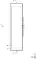
图1是表示第1实施方式的电子镜的一例的主视图。FIG. 1 is a front view showing an example of an electronic mirror according to the first embodiment.
图2是表示第1实施方式的电子镜的一例的分解立体图。FIG. 2 is an exploded perspective view showing an example of the electronic mirror according to the first embodiment.
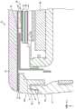
图3是图1所示的电子镜的A-A向视的剖视图。FIG. 3 is a cross-sectional view of the electronic mirror shown in FIG. 1 viewed from the arrow A-A.
图4是表示第2实施方式的电子镜的一例的分解立体图。4 is an exploded perspective view showing an example of an electronic mirror according to a second embodiment.
图5是第2实施方式的电子镜的剖视图。5 is a cross-sectional view of an electronic mirror according to a second embodiment.
图6是表示第3实施方式的电子镜的一例的分解立体图。6 is an exploded perspective view showing an example of an electronic mirror according to a third embodiment.
图7是第3实施方式的电子镜的剖视图。7 is a cross-sectional view of an electronic mirror according to a third embodiment.
图8是表示第4实施方式的电子镜的一例的主视图。8 is a front view showing an example of an electronic mirror according to a fourth embodiment.
图9是表示第4实施方式的电子镜的一例的分解立体图。9 is an exploded perspective view showing an example of an electronic mirror according to a fourth embodiment.
图10是图8所示的电子镜的A-A向视的剖视图。FIG. 10 is a cross-sectional view of the electronic mirror shown in FIG. 8 viewed from the arrow A-A.
具体实施方式Detailed ways
以下,适当参照附图,详细地说明本公开的实施方式。不过,有时省略过于详细的说明。另外,附图和以下的说明是为了使本领域技术人员充分地理解本公开而提供的,并非意图由此限定实用新型授权权利要求书所记载的主题。Hereinafter, embodiments of the present disclosure will be described in detail with reference to the drawings as appropriate. However, overly detailed explanations are sometimes omitted. In addition, the drawings and the following descriptions are provided to enable those skilled in the art to fully understand the present disclosure, and are not intended to limit the subject matter described in the utility model patent claims.
(第1实施方式)(first embodiment)
图1是表示第1实施方式的电子镜1的一例的主视图。图2是表示第1实施方式的电子镜1的一例的分解立体图。图3是图1所示的电子镜1的A-A向视的剖视图。另外,将电子镜1的宽度方向设为X轴方向,将电子镜1的高度方向设为Y轴方向,将电子镜1的深度方向设为Z轴方向。此外,将在电子镜1中显示图像的一侧设为正面侧,将与正面侧相反的那一侧设为背面侧。FIG. 1 is a front view showing an example of an
电子镜1例如是配置于车辆的室内的电子内镜。电子镜1作为显示装置和镜发挥功能。具体而言,电子镜1在作为显示装置发挥功能的情况下显示拍摄车辆的后方的摄像机拍摄到的图像。此外,电子镜1在作为镜发挥功能的情况下通过反射光来映射车辆的后方。此外,电子镜1是显示装置和车载显示装置的一例。The
电子镜1具有作为显示装置发挥功能的显示器模式和作为镜发挥功能的镜模式。显示器模式是电子镜1显示拍摄车辆的后方的摄像机拍摄到的图像的模式。镜模式是电子镜1通过使入射到电子镜1的光反射来映射车辆的后方的模式。例如,电子镜1通过接受利用杆等进行的操作来切换显示器模式和镜模式。The
如图2所示,电子镜1具有罩透镜10、双面胶带20、框架30、显示器40以及外壳50。罩透镜10是使可见光透过的罩。更详细而言,罩透镜10以覆盖电子镜1的正面的方式由透明的构件形成。例如,罩透镜10由树脂形成。罩透镜10也可以由玻璃形成。罩透镜10由树脂形成,从而与由玻璃形成的情况相比轻量化。As shown in FIG. 2 , the
此外,罩透镜10在与框架30对应的位置具有通过反射可见光来映射图像的镜部11。与框架30对应的位置是指在从正面观察电子镜1时至少局部与框架30重叠的位置。镜部11也可以以在从正面观察电子镜1时与框架30的整体重叠或自框架30伸出的方式形成。镜部11是利用形成为镜面状的银色的覆膜使入射的光反射的部分。由此,镜部11像镜子那样映射图像。在此,罩透镜10是透明的,因此有时能够经由罩透镜10视觉辨认处于比罩透镜10靠背面侧的位置的构件。处于背面侧的构件例如是后述的双面胶带20和框架30。在罩透镜10设置镜部11,从而镜部11能够遮挡双面胶带20、框架30,而且映射车辆的后方。由此,电子镜1在镜模式的情况下能够使整面成为镜子。In addition, the
双面胶带20是在两面涂布有粘接剂的带。双面胶带20将罩透镜10和框架30粘接。The double-
框架30是与外壳50接合且覆盖显示器40的边缘的外框。此外,框架30支承罩透镜10。例如,框架30通过利用双面胶带20粘贴来支承罩透镜10。The
此外,框架30包括覆盖显示器40的边缘的外框部31和与外壳50接合的接合部32。外框部31具有与显示器40所具有的LCD(Liquid Crystal Display)单元44大致平行且覆盖显示器40的边缘的平面状的板。接合部32具有供外壳50所具有的凸部54插入的凹部33。接合部32通过向凹部33插入凸部54而与外壳50接合。In addition, the
显示器40显示图像。更详细而言,显示器40显示拍摄车辆的后方的摄像机拍摄到的图像。另外,显示器40只要通过有线或无线的方式连接,就不限于显示拍摄车辆的后方的摄像机拍摄到的图像,也可以显示其他摄像机拍摄到的图像。The
此外,在显示器40和框架30之间配置有垫片41。垫片41填充显示器40和框架30之间的间隙。由此,垫片41抑制尘埃、尘土等垃圾进入到电子镜1的内部的情况。In addition, a
显示器40包括显示器壳体42、偏振光反射层43、LCD单元44以及显示器控制部46。显示器壳体42是覆盖显示器40的壳体。The
偏振光反射层43设于罩透镜10和显示器40之间且是显示器40的表面441。此外,偏振光反射层43使经由罩透镜10入射的光的一部分反射且使显示器40显示的图像的光透过。偏振光反射层43是偏振光反射部的一例。即,偏振光反射层43在镜模式的情况下作为镜子反射光,在显示器模式的情况下使显示器40显示的图像的光朝向正面侧透过。The polarized
更详细而言,偏振光反射层43使向特定方向偏振或极化的光透过,使与特定方向不同的方向的光反射。此外,偏振光反射层43使LCD单元44出射的光透过。此外,偏振光反射层43利用OCA(Optical Clear Adhesive)等透明的粘接剂45粘贴于显示器40的表面441。具体而言,偏振光反射层43粘贴于LCD单元44的表面441。More specifically, the
LCD单元44是在玻璃基板之间注入有液晶的构件。显示器40通过经由LCD单元44出射光来显示图像。The
显示器控制部46控制显示器40。例如,显示器控制部46具有控制显示器40的电路基板、向LCD单元44放射光的背光源、从搭载于车辆的摄像机接收图像的接收部等。显示器控制部46在显示器模式的情况下使搭载于车辆的摄像机拍摄到的图像显示于LCD单元44。The
外壳50收纳显示器40且安装于车辆。外壳50包括收纳部51、臂部52以及安装部53。收纳部51是收纳显示器40的壳体。此外,收纳部51在正面侧具有凸部54。凸部54向在框架30的接合部32设置的凹部33插入。由此,外壳50的收纳部51与框架30接合。而且,外壳50和框架30是覆盖显示器40的周围的壳体。即,外壳50和框架30是壳体的一例。The
臂部52是将外壳50和安装部53连结的臂状的构件。此外,臂部52也可以具有变更显示器40的角度的关节。由此,使用者能够将电子镜1调整为易于观察的角度。例如,电子镜1也可以在显示器模式和镜模式中能够变更角度。The
安装部53是安装于车辆的室内的构件。例如,安装部53安装于车辆的顶棚、前挡风玻璃。由此,电子镜1安装于车辆。The mounting
像以上那样,第1实施方式的电子镜1包括使可见光透过的罩透镜10、显示图像的显示器40以及配置于显示器40的LCD单元44的偏振光反射层43。而且,偏振光反射层43使经由罩透镜10入射的光反射且使显示于LCD单元44的图像的光偏振。即,偏振光反射层43还作为使显示于LCD单元44的图像的光偏振的偏振片发挥功能。由此,电子镜1能够消除多个构件的作用的重复。As described above, the
此外,电子镜1在LCD单元44配置有偏振光反射层43。由此,能够由比玻璃轻量的树脂形成罩透镜10。在此,树脂比玻璃柔软,易于变形。因此,若在由树脂形成的罩透镜配置偏振光反射层,则难以维持偏振光反射层的平面度,存在反射图像失真这样的问题。在第1实施方式的电子镜1中,在硬度较高的LCD单元44配置有偏振光反射层43。由此,能够维持电子镜1的偏振光反射层43的平面度,能够抑制反射图像失真的情况。In addition, in the
此外,如图3所示,罩透镜10粘贴于框架30的正面侧。框架30也可以具有覆盖罩透镜10的端的边缘。在一些国家、地区,根据法规要求具有覆盖罩透镜10的端的边缘,因此能够在这样的国家、地区利用电子镜1。In addition, as shown in FIG. 3 , the
(第2实施方式)(second embodiment)
图4是表示第2实施方式的电子镜1a的一例的分解立体图。图5是第2实施方式的电子镜1a的剖视图。另外,由于第2实施方式的电子镜1a的正面与图1所示的第1实施方式的电子镜1大致相同,因此省略主视图。FIG. 4 is an exploded perspective view showing an example of the electronic mirror 1a of the second embodiment. FIG. 5 is a cross-sectional view of an electronic mirror 1a according to the second embodiment. In addition, since the front of the electronic mirror 1 a of the second embodiment is substantially the same as the
如图4所示,电子镜1a具有罩透镜10a、OCA 60、VRM(Variable ReflectanceMirror)70、双面胶带20、框架30a、显示器40以及外壳50。As shown in FIG. 4 , the electronic mirror 1 a has a
电子镜1a具有在镜模式的情况下作为镜发挥功能的VRM 70。在罩透镜10a的从罩透镜10a的边缘到设有VRM 70的位置的区域设有像镜子那样映射图像的镜部11。在图5所示的例子中,在从正面观察电子镜1a时,在比设有VRM 70的位置靠外侧的位置设有镜部11。The electronic mirror 1a has a
OCA 60是将罩透镜10a和VRM 70粘接的透明的粘接剂。The
VRM 70根据被施加的电压来变更针对入射光的反射率和透过率。例如,VRM 70在显示器模式的情况下提高针对入射光的透过率。即,VRM 70使配置于比VRM 70靠背面侧的位置的显示器40显示的图像的光透过。另一方面,VRM 70在镜模式的情况下提高针对入射光的反射率。即,VRM 70使经由罩透镜10a入射的光反射。The
VRM 70具有偏振部71、TN(Twisted Nematic)液晶部72以及粘接剂73。此外,在LCD单元44的表面441设置的偏振光反射层43作为VRM 70的局部发挥功能。The
偏振部71设于罩透镜10a和偏振光反射层43之间且是靠罩透镜10a侧的位置,使经由罩透镜10a入射的光偏振。更详细而言,偏振部71是使经由罩透镜10a入射的光中的向特定方向偏振或极化的光透过的偏振片。此外,偏振部71吸收与特定方向不同的方向的光。The
TN液晶部72是TN方式的液晶板。TN液晶部72位于偏振部71和偏振光反射层43之间,变更经由偏振部71入射的光的偏振方向。TN液晶部72是液晶部的一例。更详细而言,TN液晶部72在被施加电压的情况下将液晶材料的分子的排列方式变为垂直方向。由此,TN液晶部72使透过的光直向前进。另一方面,TN液晶部72在未被施加电压的情况下不变更液晶材料的分子的排列方式。由此,TN液晶部72变更透过TN液晶部72的光的偏振方向。例如,TN液晶部72将光的偏振方向偏转90度。液晶部的例子不限于此。例如,也可以是在被施加电压的情况下变更透过的光的偏振方向且在未被施加电压的情况下使透过的光直向前进这样的液晶部。The TN
此外,TN液晶部72利用粘接剂73粘贴于偏振部71。粘接剂73与粘接剂45同样,能够使用透明的OCA等。In addition, the TN
偏振光反射层43使与偏振部71相同方向的光透过。换言之,偏振光反射层43使在TN液晶部72中直向前进的光透过。此外,偏振光反射层43使被TN液晶部72改变了偏振方向的光反射。由此,偏振光反射层43使经由TN液晶部72入射的光的一部反射且使显示器40显示的图像的光透过。The polarized
在这样的结构中,在显示器模式的情况下,偏振光反射层43使LCD单元44显示的图像的光中的向特定方向偏振或极化的光透过。此外,在显示器模式的情况下,对VRM 70施加电压。由此,TN液晶部72不变更从偏振光反射层43入射的光的偏振方向而使其直向前进。此外,透过TN液晶部72的光透过偏振部71。然后,透过偏振部71的光经由OCA 60和罩透镜10a放出。由此,电子镜1a显示图像。In such a structure, in the case of the display mode, the polarized
另一方面,在镜模式的情况下,不对TN液晶部72施加电压。由此,TN液晶部72利用液晶材料的分子变更从偏振部71入射的光的偏振方向。然后,偏振光反射层43使被TN液晶部72改变了偏振方向的光反射。On the other hand, in the mirror mode, no voltage is applied to the TN
TN液晶部72变更偏振光反射层43反射的光的偏振方向。其结果,透过TN液晶部72的光恢复为透过偏振部71时的角度。然后,透过TN液晶部72的光透过偏振部71。透过偏振部71的光经由OCA 60和罩透镜10a放出。这样,电子镜1a在镜模式中反射光。The TN
如图5所示,TN液晶部72和偏振部71配置于罩透镜10a和框架30a之间。框架30a为了设置供TN液晶部72和偏振部71配置的空间而具有台阶形状。框架30a在比利用双面胶带20与罩透镜10a粘接的面低一层的位置具有供TN液晶部72和偏振部71配置的配置部34。而且,显示器40配置于比配置部34靠背面侧的位置。As shown in FIG. 5, the TN
像以上那样,第2实施方式的电子镜1a包括设于罩透镜10a和偏振光反射层43之间且使经由罩透镜10a入射的光偏振的偏振部71和变更经由偏振部71入射的光的偏振方向的TN液晶部72。而且,在显示器40的LCD单元44配置的偏振光反射层43还作为VRM 70的偏振光反射板发挥功能。由此,电子镜1a能够在多个构件中消除作用的重复。As described above, the electronic mirror 1a of the second embodiment includes the
此外,如图5所示,罩透镜10a粘贴于框架30a的正面侧。框架30a也可以具有覆盖罩透镜10a的端的边缘。在一些国家、地区,根据法规要求具有覆盖罩透镜10a的端的边缘,因此能够在这样的国家、地区利用电子镜1a。Moreover, as shown in FIG. 5, the
(第3实施方式)(third embodiment)
图6是表示第3实施方式的电子镜1b的一例的分解立体图。图7是第3实施方式的电子镜1b的剖视图。另外,由于第3实施方式的电子镜1b的正面与图1所示的第1实施方式的电子镜1大致相同,因此省略主视图。FIG. 6 is an exploded perspective view showing an example of the
如图6所示,电子镜1b具有罩透镜10、OCA 60、显示器40、双面胶带20、框架30b以及外壳50。As shown in FIG. 6 , the
OCA 60是透明的粘接剂。罩透镜10和显示器40由OCA 60粘接。更详细而言,OCA 60将罩透镜10和在LCD单元44的表面441形成的偏振光反射层43粘接。换言之,罩透镜10和显示器40由OCA 60粘接。因此,如图7所示,框架30b没有覆盖显示器40的边缘的外框。
显示器40利用OCA 60粘接于罩透镜10。此外,显示器40具有LCD单元44,该LCD单元44显示搭载于车辆的摄像机拍摄到的图像。而且,LCD单元44在正面侧的表面441具有偏振光反射层43。The
像以上那样,在第3实施方式的电子镜1b中,罩透镜10和配置有偏振光反射层43的LCD单元44由OCA 60粘接。在该情况下也是,偏振光反射层43使经由罩透镜10入射的光反射,使显示于LCD单元44的图像的光偏振。即,偏振光反射层43还作为使显示于LCD单元44的图像的光偏振的偏振片发挥功能。由此,电子镜1b能够在多个构件中消除作用的重复。As described above, in the
此外,如图7所示,罩透镜10粘贴于框架30b的正面侧。框架30b也可以具有覆盖罩透镜10的端的边缘。在一些国家、地区,根据法规要求具有覆盖罩透镜10的端的边缘,因此能够在这样的国家、地区利用电子镜1b。Moreover, as shown in FIG. 7, the
(第4实施方式)(fourth embodiment)
图8是表示第4实施方式的电子镜1c的一例的主视图。图9是表示第4实施方式的电子镜1c的一例的分解立体图。图10是图8所示的电子镜1c的A-A向视的剖视图。FIG. 8 is a front view showing an example of an
第4实施方式的电子镜1c不具有电子镜1的罩透镜10和双面胶带20。即,如图9所示,电子镜1c具有框架30c、显示器40以及外壳50。The
如图10所示,电子镜1c没有罩透镜10,因此显示器40暴露。更详细而言,在电子镜1c中,在LCD单元44的表面441设置的偏振光反射层43暴露。即,偏振光反射层43设于显示器40的表面441,使从显示器40的相反侧入射的光的一部分反射且使显示器40显示的图像的光透过。As shown in FIG. 10, the
此外,由于没有罩透镜10,因此框架30c成为显示器40的外框。由此,框架30c成为具有曲线的外观。Moreover, since there is no
像以上那样,第4实施方式的电子镜1c不具有罩透镜10。在该情况下也是,偏振光反射层43使入射的光反射,使显示于LCD单元44的图像的光偏振。即,偏振光反射层43还作为使显示于LCD单元44的图像的光偏振的偏振片发挥功能。由此,电子镜1c能够在多个构件中消除作用的重复。As described above, the
说明了本公开的几个实施方式,但这些实施方式是作为例子而提出的,并非意图限定实用新型的范围。这些实施方式能够以其他各种形态实施,在不脱离实用新型的主旨的范围内,能够进行各种省略、替换、变更。这些实施方式、其变形包含于实用新型的范围、主旨,同样包含于实用新型授权权利要求书所记载的实用新型和其等同的范围。Although some embodiments of the present disclosure have been described, these embodiments are presented as examples and are not intended to limit the scope of the invention. These embodiments can be implemented in other various forms, and various omissions, substitutions, and changes can be made without departing from the scope of the invention. These embodiments and modifications thereof are included in the scope and gist of the utility model, and are also included in the utility model described in the utility model patent claims and the equivalent range thereof.
Claims (8)
Translated fromChineseApplications Claiming Priority (2)
| Application Number | Priority Date | Filing Date | Title |
|---|---|---|---|
| JP2022-011266 | 2022-01-27 | ||
| JP2022011266AJP2023109630A (en) | 2022-01-27 | 2022-01-27 | Display device and in-vehicle display device |
Publications (1)
| Publication Number | Publication Date |
|---|---|
| CN219122922Utrue CN219122922U (en) | 2023-06-02 |
Family
ID=84890238
Family Applications (1)
| Application Number | Title | Priority Date | Filing Date |
|---|---|---|---|
| CN202223275944.9UActiveCN219122922U (en) | 2022-01-27 | 2022-12-07 | Display device and vehicle-mounted display device |
Country Status (4)
| Country | Link |
|---|---|
| US (1) | US20230236456A1 (en) |
| JP (1) | JP2023109630A (en) |
| CN (1) | CN219122922U (en) |
| DE (1) | DE202022106842U1 (en) |
Families Citing this family (2)
| Publication number | Priority date | Publication date | Assignee | Title |
|---|---|---|---|---|
| USD1086283S1 (en)* | 2024-02-05 | 2025-07-29 | Toyota Jidosha Kabushiki Kaisha | Vehicle mounted information display device |
| USD1078671S1 (en)* | 2024-08-20 | 2025-06-10 | Shenzhen Yuzhongqi Technology Co., Ltd. | Vehicle display device |
Family Cites Families (9)
| Publication number | Priority date | Publication date | Assignee | Title |
|---|---|---|---|---|
| EP1949666B1 (en)* | 2005-11-01 | 2013-07-17 | Magna Mirrors of America, Inc. | Interior rearview mirror with display |
| JP2010221899A (en)* | 2009-03-24 | 2010-10-07 | Murakami Corp | Vehicular mirror with monitor |
| EP2947506A4 (en)* | 2013-01-16 | 2016-07-13 | Sharp Kk | Mirror display, half mirror plate, and electronic device |
| US10227046B2 (en)* | 2014-10-27 | 2019-03-12 | Magna Mirrors Of America, Inc. | Sun visor and vanity mirror assembly for vehicle |
| JP2017111267A (en) | 2015-12-16 | 2017-06-22 | 富士フイルム株式会社 | Mirror with vehicle-purposed image display function, and manufacturing method of the same |
| KR20180086262A (en)* | 2015-12-17 | 2018-07-30 | 쓰리엠 이노베이티브 프로퍼티즈 컴파니 | A mirror comprising a reflective backlit display |
| US20190086723A1 (en)* | 2017-09-20 | 2019-03-21 | Visteon Global Technologies, Inc. | Electronic mirror with an enhanced switch-able lens system |
| JP7411889B2 (en)* | 2020-03-27 | 2024-01-12 | パナソニックIpマネジメント株式会社 | Display device and control circuit |
| US11766968B2 (en)* | 2021-05-18 | 2023-09-26 | Magna Mirrors Of America, Inc. | Vehicular interior rearview mirror assembly with video mirror display and VRLC stack |
- 2022
- 2022-01-27JPJP2022011266Apatent/JP2023109630A/enactivePending
- 2022-12-02USUS18/074,030patent/US20230236456A1/ennot_activeAbandoned
- 2022-12-07CNCN202223275944.9Upatent/CN219122922U/enactiveActive
- 2022-12-07DEDE202022106842.9Upatent/DE202022106842U1/enactiveActive
Also Published As
| Publication number | Publication date |
|---|---|
| JP2023109630A (en) | 2023-08-08 |
| DE202022106842U1 (en) | 2022-12-23 |
| US20230236456A1 (en) | 2023-07-27 |
Similar Documents
| Publication | Publication Date | Title |
|---|---|---|
| CN219122922U (en) | Display device and vehicle-mounted display device | |
| TWI652526B (en) | Display assembly mechanism and related display device | |
| JP4330764B2 (en) | Liquid crystal display | |
| US7528798B2 (en) | Head-up display device | |
| US7738244B2 (en) | Display device | |
| CN103163647B (en) | Head-up display | |
| CN110174764A (en) | Projection arrangement and display apparatus | |
| CN110174766A (en) | Display apparatus | |
| US9637054B2 (en) | Switchable rearview mirror element with anti-reflection mechanisms for use with a display | |
| CN108983481B (en) | mirror display device | |
| CN113495382A (en) | Display device | |
| JP2019095477A (en) | Vehicle-purpose inner mirror | |
| CN112874440B (en) | Rearview mirror and vehicle having the same | |
| EP3460536A1 (en) | Electronic mirror with an enhanced switchable lens system | |
| JP2010276776A (en) | Head-up display device | |
| JPS62283388A (en) | Mirror reflection type display unit | |
| KR100407291B1 (en) | Display module | |
| JP2009109798A (en) | Headup display device | |
| CN115631679A (en) | Privacy Display Device | |
| JP2002260426A (en) | Display device and lighting device | |
| US12345973B2 (en) | Display device | |
| CN217672166U (en) | Instrument display device and vehicle | |
| CN222769251U (en) | Reflection unit for panoramic head-up display and panoramic head-up display system | |
| US12422711B2 (en) | Display apparatus | |
| CN103105687A (en) | Display device |
Legal Events
| Date | Code | Title | Description |
|---|---|---|---|
| GR01 | Patent grant | ||
| GR01 | Patent grant | ||
| TR01 | Transfer of patent right | Effective date of registration:20240326 Address after:Kanagawa Prefecture, Japan Patentee after:Panasonic Automotive Electronic Systems Co.,Ltd. Country or region after:Ri Ben Address before:Osaka, Japan Patentee before:PANASONIC INTELLECTUAL PROPERTY MANAGEMENT Co.,Ltd. Country or region before:Ri Ben | |
| TR01 | Transfer of patent right |