CN219091232U - A waste water treatment mechanism for warp knitting machine - Google Patents
A waste water treatment mechanism for warp knitting machineDownload PDFInfo
- Publication number
- CN219091232U CN219091232UCN202223004643.2UCN202223004643UCN219091232UCN 219091232 UCN219091232 UCN 219091232UCN 202223004643 UCN202223004643 UCN 202223004643UCN 219091232 UCN219091232 UCN 219091232U
- Authority
- CN
- China
- Prior art keywords
- warp knitting
- water
- knitting machine
- frame body
- tank
- Prior art date
- Legal status (The legal status is an assumption and is not a legal conclusion. Google has not performed a legal analysis and makes no representation as to the accuracy of the status listed.)
- Expired - Fee Related
Links
- 238000009940knittingMethods0.000titleclaimsabstractdescription52
- 230000007246mechanismEffects0.000titleclaimsabstractdescription18
- 238000004065wastewater treatmentMethods0.000titleclaimsabstractdescription18
- XLYOFNOQVPJJNP-UHFFFAOYSA-NwaterSubstancesOXLYOFNOQVPJJNP-UHFFFAOYSA-N0.000claimsabstractdescription81
- 238000004804windingMethods0.000claimsabstractdescription16
- 238000003860storageMethods0.000claimsabstractdescription11
- 238000007789sealingMethods0.000claimsabstractdescription10
- 230000005540biological transmissionEffects0.000claimsdescription5
- 238000009434installationMethods0.000claims2
- 239000002351wastewaterSubstances0.000abstractdescription17
- 239000007921spraySubstances0.000abstractdescription7
- 238000005507sprayingMethods0.000abstractdescription4
- 239000010918textile wastewaterSubstances0.000abstract1
- 239000004744fabricSubstances0.000description8
- 238000000034methodMethods0.000description5
- OKTJSMMVPCPJKN-UHFFFAOYSA-NCarbonChemical compound[C]OKTJSMMVPCPJKN-UHFFFAOYSA-N0.000description4
- 238000010409ironingMethods0.000description4
- 239000004753textileSubstances0.000description3
- 230000001877deodorizing effectEffects0.000description2
- 238000010586diagramMethods0.000description2
- 239000003344environmental pollutantSubstances0.000description2
- 238000012423maintenanceMethods0.000description2
- 238000004519manufacturing processMethods0.000description2
- 239000005416organic matterSubstances0.000description2
- 231100000719pollutantToxicity0.000description2
- 230000008569processEffects0.000description2
- 230000009471actionEffects0.000description1
- 230000002411adverseEffects0.000description1
- 230000009286beneficial effectEffects0.000description1
- 238000007599dischargingMethods0.000description1
- 238000001035dryingMethods0.000description1
- 230000000694effectsEffects0.000description1
- 230000005611electricityEffects0.000description1
- 238000005516engineering processMethods0.000description1
- 239000000463materialSubstances0.000description1
- 238000005096rolling processMethods0.000description1
- 230000003068static effectEffects0.000description1
- 239000002699waste materialSubstances0.000description1
Images

Classifications
- Y—GENERAL TAGGING OF NEW TECHNOLOGICAL DEVELOPMENTS; GENERAL TAGGING OF CROSS-SECTIONAL TECHNOLOGIES SPANNING OVER SEVERAL SECTIONS OF THE IPC; TECHNICAL SUBJECTS COVERED BY FORMER USPC CROSS-REFERENCE ART COLLECTIONS [XRACs] AND DIGESTS
- Y02—TECHNOLOGIES OR APPLICATIONS FOR MITIGATION OR ADAPTATION AGAINST CLIMATE CHANGE
- Y02W—CLIMATE CHANGE MITIGATION TECHNOLOGIES RELATED TO WASTEWATER TREATMENT OR WASTE MANAGEMENT
- Y02W10/00—Technologies for wastewater treatment
- Y02W10/10—Biological treatment of water, waste water, or sewage
Landscapes
- Knitting Machines (AREA)
Abstract
Description
Translated fromChinese技术领域technical field
本实用新型涉及经编机技术领域,特别涉及一种经编机废水处理机构。The utility model relates to the technical field of warp knitting machines, in particular to a waste water treatment mechanism for warp knitting machines.
背景技术Background technique
经编机是用一组或几组平行排列的纱线,于经向喂入机器的所有工作针上,同时成圈而形成针织物,这种方法称为经编,织物称为经编织物,而纺织车间内经编机周围的湿度对纱线生产来说显得非常重要,如经编机周围的空气过为干燥,纱线内部的水分会很快被蒸发出来,从而使纱线变得干燥,干燥的纱线会降低纺织品的韧性,在生产的运作过程中摩擦产生大量的静电,使纱线断头、起毛、废品增多,难度增大,为此,急需对经编机的周围进行喷雾,防止干燥的问题对纺织品的整体工艺带来不利的影响。The warp knitting machine uses one or several groups of yarns arranged in parallel to form a loop at the same time on all the working needles of the warp feeding machine. This method is called warp knitting, and the fabric is called warp knitted fabric. , and the humidity around the warp knitting machine in the textile workshop is very important for yarn production. If the air around the warp knitting machine is too dry, the moisture inside the yarn will evaporate quickly, thus making the yarn dry , dry yarn will reduce the toughness of textiles, and friction will generate a lot of static electricity during the production process, causing yarn breakage, fluffing, and waste products to increase, making it more difficult. For this reason, it is urgent to spray around the warp knitting machine , to prevent the problem of drying from adversely affecting the overall process of textiles.
专利号CN206616334U的实用新型公开了一种经编机的收卷装置,包括支架、传输辊、收卷辊、加湿辊和熨烫辊,布料依次通过传输辊、加湿辊、熨烫辊和收卷辊,通过加湿辊对布料进行加湿处理,然后使用熨烫辊对布料进行熨烫,保证布料的平整收卷。本实用新型的优点在于:通过先加湿后熨烫的方式,使得收卷后的布料平整无褶皱,提高布料收卷质量。The utility model of patent No. CN206616334U discloses a winding device of a warp knitting machine, including a bracket, a transmission roller, a winding roller, a humidifying roller and an ironing roller, and the cloth passes through the conveying roller, the humidifying roller, the ironing roller and the winding roller in turn. The cloth is humidified by the humidifying roller, and then the cloth is ironed with the ironing roller to ensure the smooth winding of the cloth. The utility model has the advantages that: through the method of humidifying first and then ironing, the rolled cloth is smooth and wrinkle-free, and the rolling quality of the cloth is improved.
现有的经编机存在以下缺点:缺乏对喷雾产生的废水进行处理的结构,虽设置有喷雾结构,但是无法将喷雾产生的废水进行处理,实用性不好。为此,我们提出一种经编机废水处理机构。The existing warp knitting machine has the following disadvantages: it lacks a structure for treating the waste water produced by spraying. Although a spray structure is provided, the waste water produced by spraying cannot be treated, and the practicability is not good. For this reason, we propose a kind of waste water treatment mechanism of warp knitting machine.
实用新型内容Utility model content
本实用新型的主要目的在于提供一种经编机废水处理机构,可以有效解决背景技术中的问题。The main purpose of the utility model is to provide a waste water treatment mechanism for warp knitting machines, which can effectively solve the problems in the background technology.
为实现上述目的,本实用新型采取的技术方案为:In order to achieve the above object, the technical scheme that the utility model takes is:
一种经编机废水处理机构,包括经编机架体,所述经编机架体的顶部设置有储水罐,所述经编机架体内部的上端设有整经辊,所述经编机架体内部的上端且位于整经辊的下端设有集水槽,所述集水槽的底部设置有喷水头,所述集水槽的下端设置有导纱板,所述经编机架体的一端设置有水槽,所述水槽的上端设有绕线辊,所述水槽内底部的两端均开设有排水口,所述水槽底部的两端均设置有密封塞,所述滤网的外侧通过开设第一螺纹孔设有紧固螺钉,所述排水口的外侧开设有与第一螺纹孔相对应的第二螺纹孔。A wastewater treatment mechanism for a warp knitting machine, comprising a warp knitting frame body, a water storage tank is arranged on the top of the warp knitting frame body, a warping roller is arranged at the upper end of the warp knitting frame body, and the warp knitting frame body The upper end inside the knitting frame body and the lower end of the warping rollers are provided with a water collection tank, the bottom of the water collection tank is provided with a water spray head, the lower end of the water collection tank is provided with a yarn guide plate, and the warp knitting frame body One end of the water tank is provided with a water tank, the upper end of the water tank is provided with a winding roller, both ends of the inner bottom of the water tank are provided with drain ports, both ends of the bottom of the water tank are provided with sealing plugs, and the outside of the filter screen A fastening screw is provided by opening a first threaded hole, and a second threaded hole corresponding to the first threaded hole is opened on the outer side of the water outlet.
进一步地,所述水槽的两端均通过螺钉安装有U型安装架,所述U型安装架的顶部焊接有支撑块,所述绕线辊的两端分别连接有第一转杆和第二转杆,所述第一转杆和第二转杆均贯穿支撑块。Further, both ends of the water tank are installed with U-shaped mounting brackets through screws, and the top of the U-shaped mounting frame is welded with a support block, and the two ends of the winding roller are respectively connected with the first rotating rod and the second rotating rod. The rotating rod, the first rotating rod and the second rotating rod both pass through the support block.
进一步地,所述储水罐与集水槽之间连通有输水管,所述输水管上设置有自吸泵。Further, a water delivery pipe is connected between the water storage tank and the sump, and a self-priming pump is arranged on the water delivery pipe.
进一步地,所述水槽的一侧焊接有第二安装板且第二安装板的顶部安装有第二驱动电机,所述第二转杆的外围与第二驱动电机输出轴的外围之间均套设有传动带。Further, a second mounting plate is welded on one side of the water tank and a second drive motor is installed on the top of the second mounting plate, and the periphery of the second rotating rod is evenly sleeved with the periphery of the output shaft of the second drive motor. Equipped with drive belt.
进一步地,所述经编机架体的一侧焊接有第一安装板且第一安装板的顶部安装有第一驱动电机,所述第一驱动电机的输出轴与整经辊连接。Further, a first mounting plate is welded on one side of the warp knitting frame body and a first driving motor is installed on the top of the first mounting plate, and the output shaft of the first driving motor is connected to the warping roller.
与现有技术相比,本实用新型具有如下有益效果:Compared with the prior art, the utility model has the following beneficial effects:
1.本实用新型一种经编机废水处理机构,通过储水罐、集水槽、喷水头、水槽、排水口、滤网和密封塞,集水槽上的喷水头将水分施加于纱线的表面,纱线上的水分逐渐的滴入水槽的内部,人员用密封塞将排水口进行封堵,水分可暂时存储于水槽的内部,人员将密封塞从排水口的内部拔出,使得废水能够产生流动,废水流经排水口顶部的滤网,滤网可以吸附废水中有机物,能够有效的将废水中的污染物去除,使得处理后的废水达到排放标准,被处理后的废水即可经排水口而流出水槽,达到对废水进行净化排放的目的。1. The utility model is a waste water treatment mechanism for warp knitting machines, which applies water to the yarn through the water storage tank, water collection tank, water spray head, water tank, drain outlet, filter screen and sealing plug, and the water spray head on the water collection tank On the surface of the water tank, the water on the yarn gradually drips into the inside of the water tank, and the personnel use the sealing plug to seal the drain, the water can be temporarily stored in the inside of the water tank, and the personnel pull out the sealing plug from the inside of the water tank to make the waste water It can generate flow, and the waste water flows through the filter at the top of the drain. The filter can absorb the organic matter in the waste water, and can effectively remove the pollutants in the waste water, so that the treated waste water can meet the discharge standard, and the treated waste water can be passed through The drain outlet flows out of the water tank to achieve the purpose of purifying and discharging the waste water.
2.本实用新型一种经编机废水处理机构,通过第一螺纹孔、紧固螺钉和第二螺纹孔,人员将紧固螺钉依次穿过第一螺纹孔和第二螺纹孔,即可将滤网与排水口可拆卸连接,便于保养、更换。2. The utility model is a wastewater treatment mechanism for warp knitting machines. Through the first threaded hole, the fastening screw and the second threaded hole, the personnel pass the fastening screw through the first threaded hole and the second threaded hole in sequence, and then the The filter screen is detachably connected with the drain port, which is convenient for maintenance and replacement.
附图说明Description of drawings
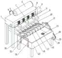
图1为本实用新型一种经编机废水处理机构的整体结构示意图。Figure 1 is a schematic diagram of the overall structure of a warp knitting machine wastewater treatment mechanism of the present invention.
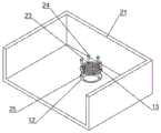
图2为本实用新型一种经编机废水处理机构水槽的仰视图。Fig. 2 is a bottom view of a water tank of a warp knitting machine wastewater treatment mechanism of the present invention.
图3为本实用新型一种经编机废水处理机构的排水口和滤网结构示意图。Fig. 3 is a structural schematic diagram of a drain port and a filter screen of a warp knitting machine waste water treatment mechanism of the present invention.
图中:1、经编机架体;2、储水罐;3、输水管;4、自吸泵;5、第一安装板;6、第一驱动电机;7、整经辊;8、集水槽;9、喷水头;10、绕线辊;11、纱线;12、排水口;13、滤网;14、U型安装架;15、支撑块;16、第一转杆;17、第二转杆;18、第二安装板;19、第二驱动电机;20、传动带;21、水槽;22、密封塞;23、第一螺纹孔;24、紧固螺钉;25、第二螺纹孔;26、导纱板。In the figure: 1. warp knitting frame body; 2. water storage tank; 3. water delivery pipe; 4. self-priming pump; 5. first mounting plate; 6. first driving motor; 7. warping roller; 8. Sump; 9, sprinkler head; 10, winding roller; 11, yarn; 12, drain outlet; 13, filter screen; 14, U-shaped mounting frame; 15, support block; 16, first rotating rod; 17 , the second rotating rod; 18, the second mounting plate; 19, the second driving motor; 20, the transmission belt; 21, the water tank; 22, the sealing plug; 23, the first threaded hole; 24, the fastening screw; 25, the second Threaded hole; 26, yarn guide plate.
具体实施方式Detailed ways
为使本实用新型实现的技术手段、创作特征、达成目的与功效易于明白了解,下面结合具体实施方式,进一步阐述本实用新型。In order to make the technical means, creative features, goals and effects achieved by the utility model easy to understand, the utility model will be further elaborated below in conjunction with specific embodiments.
如图1-3所示,一种经编机废水处理机构,包括经编机架体1,所述经编机架体1的顶部设置有储水罐2,所述经编机架体1内部的上端设有整经辊7,所述经编机架体1内部的上端且位于整经辊7的下端设有集水槽8,所述集水槽8的底部设置有喷水头9,所述集水槽8的下端设置有导纱板26,所述经编机架体1的一端设置有水槽21,所述水槽21的上端设有绕线辊10,所述水槽21内底部的两端均开设有排水口12,所述水槽21底部的两端均设置有密封塞22,所述滤网13的外侧通过开设第一螺纹孔23设有紧固螺钉24,所述排水口12的外侧开设有与第一螺纹孔23相对应的第二螺纹孔25。As shown in Figure 1-3, a kind of warp knitting machine waste water treatment mechanism comprises a warp knitting frame body 1, and the top of the warp knitting frame body 1 is provided with a water storage tank 2, and the warp knitting frame body 1 The inner upper end is provided with warping roller 7, and the upper end of described warp knitting frame body 1 interior and is positioned at the lower end of warping roller 7 is provided with sump 8, and the bottom of described sump 8 is provided with sprinkler head 9, so The lower end of the water collection tank 8 is provided with a
其中,所述水槽21的两端均通过螺钉安装有U型安装架14,所述U型安装架14的顶部焊接有支撑块15,所述绕线辊10的两端分别连接有第一转杆16和第二转杆17,所述第一转杆16和第二转杆17均贯穿支撑块15。Wherein, both ends of the
本实施例中如图1所示,支撑块15不仅能够对第一转杆16和第二转杆17进行支撑,还能够使得第一转杆16和第二转杆17进行转动,进而绕线辊10能够通过第一转杆16和第二转杆17进行转动。In this embodiment, as shown in Figure 1, the
其中,所述储水罐2与集水槽8之间连通有输水管3,所述输水管3上设置有自吸泵4。Wherein, a water delivery pipe 3 is connected between the water storage tank 2 and the water collection tank 8 , and a self-priming pump 4 is arranged on the water delivery pipe 3 .
本实施例中如图1所示,自吸泵4产生吸力,可将储水罐2内部的水分吸取并经输水管3输送至集水槽8。In this embodiment, as shown in FIG. 1 , the self-priming pump 4 generates suction, which can absorb the water inside the water storage tank 2 and transport it to the water collection tank 8 through the water delivery pipe 3 .
其中,所述水槽21的一侧焊接有第二安装板18且第二安装板18的顶部安装有第二驱动电机19,所述第二转杆17的外围与第二驱动电机19输出轴的外围之间均套设有传动带20。Wherein, one side of the
本实施例中如图1所示,第二驱动电机19产生转动后,通过传动带20的作用,即可带动第二转杆17进行转动,进而驱使绕线辊10进行转动。In this embodiment, as shown in FIG. 1 , after the
其中,所述经编机架体1的一侧焊接有第一安装板5且第一安装板5的顶部安装有第一驱动电机6,所述第一驱动电机6的输出轴与整经辊7连接。Wherein, one side of the warp knitting frame body 1 is welded with a first mounting plate 5 and a
本实施例中如图1所示,第一驱动电机6能够驱使整经辊7进行转动,进而即可将纱线11进行传送。In this embodiment, as shown in FIG. 1 , the
需要说明的是,本实用新型为一种经编机废水处理机构,工作时,第一驱动电机6可以驱使整经辊7将纱线11进行传送,纱线11经导纱板26与绕线辊10连接,绕线辊10即可将纱线11进行卷绕,进一步,自吸泵4产生吸力,可将储水罐2内部的水分吸取并经输水管3输送至集水槽8,集水槽8上的喷水头9即可将水分施加于纱线11的表面,使得经编机架体1的周围以及纱线11均保持适宜的湿度,进一步,纱线11上的水分在纱线11移动的过程中受到摩擦、挤压会脱离纱线11,并逐渐的滴入水槽21的内部,人员用密封塞22将排水口12进行封堵,水分可暂时存储于水槽21的内部,待废水量增大时,人员将密封塞22从排水口12的内部拔出,使得废水能够产生流动,废水流经排水口12顶部的滤网13,进一步,滤网13采用活性炭滤网制成,利用活性炭滤料吸附废水中有机物,并达到除味除臭的目,能够有效的将废水中的污染物去除,使得处理后的废水达到排放标准,进一步,被处理后的废水即可经排水口12而流出水槽21,进一步,人员将紧固螺钉24依次穿过第一螺纹孔23和第二螺纹孔25,即可将滤网13与排水口12可拆卸连接,便于保养、更换。It should be noted that the utility model is a waste water treatment mechanism for a warp knitting machine. During operation, the
以上显示和描述了本实用新型的基本原理和主要特征和本实用新型的优点。本行业的技术人员应该了解,本实用新型不受上述实施例的限制,上述实施例和说明书中描述的只是说明本实用新型的原理,在不脱离本实用新型精神和范围的前提下,本实用新型还会有各种变化和改进,这些变化和改进都落入要求保护的本实用新型范围内。本实用新型要求保护范围由所附的权利要求书及其等效物界定。The basic principles and main features of the present utility model and the advantages of the present utility model have been shown and described above. Those skilled in the industry should understand that the utility model is not limited by the above-mentioned embodiments. The above-mentioned embodiments and descriptions only illustrate the principles of the utility model. Without departing from the spirit and scope of the utility model, the utility model The new model also has various changes and improvements, and these changes and improvements all fall within the scope of the claimed utility model. The scope of protection required by the utility model is defined by the appended claims and their equivalents.
Claims (4)
Translated fromChinesePriority Applications (1)
| Application Number | Priority Date | Filing Date | Title |
|---|---|---|---|
| CN202223004643.2UCN219091232U (en) | 2022-11-11 | 2022-11-11 | A waste water treatment mechanism for warp knitting machine |
Applications Claiming Priority (1)
| Application Number | Priority Date | Filing Date | Title |
|---|---|---|---|
| CN202223004643.2UCN219091232U (en) | 2022-11-11 | 2022-11-11 | A waste water treatment mechanism for warp knitting machine |
Publications (1)
| Publication Number | Publication Date |
|---|---|
| CN219091232Utrue CN219091232U (en) | 2023-05-30 |
Family
ID=86466257
Family Applications (1)
| Application Number | Title | Priority Date | Filing Date |
|---|---|---|---|
| CN202223004643.2UExpired - Fee RelatedCN219091232U (en) | 2022-11-11 | 2022-11-11 | A waste water treatment mechanism for warp knitting machine |
Country Status (1)
| Country | Link |
|---|---|
| CN (1) | CN219091232U (en) |
- 2022
- 2022-11-11CNCN202223004643.2Upatent/CN219091232U/ennot_activeExpired - Fee Related
Similar Documents
| Publication | Publication Date | Title |
|---|---|---|
| CN219091232U (en) | A waste water treatment mechanism for warp knitting machine | |
| CN218711546U (en) | Cloth ironing machine | |
| CN216378553U (en) | Flame-retardant antistatic viscose yarn open-end spinning device | |
| CN216204795U (en) | Steam cleaning and drying device for cotton yarn textile processing | |
| CN214142904U (en) | Wet device that elongates of weaving cloth | |
| CN209836589U (en) | A kind of fast carding equipment for textile fabrics | |
| CN210765860U (en) | Oil spraying device for processing spunbonded needle-punched non-woven fabric | |
| CN210163653U (en) | Uniform sizing and shaping equipment for textile yarns | |
| CN211705383U (en) | Textile disinfection device for spinning | |
| CN210711874U (en) | Anti-twisting device in textile machinery | |
| CN115058838A (en) | Dyeing uniformity and textile yarn dyeing device capable of controlling dye discharge amount | |
| CN211771984U (en) | Starching mechanism of sizing machine | |
| CN205347782U (en) | Install printing and dyeing fabrics forming machine of humidifier | |
| CN112030419A (en) | Cloth dyeing machine of weaving production processing usefulness | |
| CN216107597U (en) | Warp sizing machine of lycra cotton bamboo blended woven fabric | |
| CN222684999U (en) | A textile conveying device for textile use | |
| CN222390057U (en) | Production mechanism for large-width conveying belt composite fabric | |
| CN221167044U (en) | Textile fabric wetting equipment for spinning | |
| CN222251369U (en) | Textile conveying device for spinning | |
| CN220318215U (en) | Textile fabric wetting device | |
| CN221681389U (en) | Polyester cotton yarn rinsing device | |
| CN219415569U (en) | An easy-to-install drying device for textile yarn production | |
| JPH06280155A (en) | Method for operating apparatus working discontinuously for treatment of web and its apparatus | |
| CN219342567U (en) | Alkali deweighting machine | |
| CN213267067U (en) | Padding mechanism of setting machine |
Legal Events
| Date | Code | Title | Description |
|---|---|---|---|
| GR01 | Patent grant | ||
| GR01 | Patent grant | ||
| CF01 | Termination of patent right due to non-payment of annual fee | ||
| CF01 | Termination of patent right due to non-payment of annual fee | Granted publication date:20230530 |