CN219070434U - Instrument transmission device, surgical instrument and surgical robot - Google Patents
Instrument transmission device, surgical instrument and surgical robotDownload PDFInfo
- Publication number
- CN219070434U CN219070434UCN202320351778.1UCN202320351778UCN219070434UCN 219070434 UCN219070434 UCN 219070434UCN 202320351778 UCN202320351778 UCN 202320351778UCN 219070434 UCN219070434 UCN 219070434U
- Authority
- CN
- China
- Prior art keywords
- driving
- driving rope
- rope
- instrument
- transmission device
- Prior art date
- Legal status (The legal status is an assumption and is not a legal conclusion. Google has not performed a legal analysis and makes no representation as to the accuracy of the status listed.)
- Active
Links
Images


Landscapes
- Manipulator (AREA)
Abstract
Description
Translated fromChinese技术领域technical field
本实用新型涉及手术器械技术领域,具体而言,涉及一种器械传动装置、手术器械及手术机器人。The utility model relates to the technical field of surgical instruments, in particular to an instrument transmission device, a surgical instrument and a surgical robot.
背景技术Background technique
微创手术是指利用腹腔镜、胸腔镜等现代医疗器械及相关设备在人体腔体内部施行手术的一种手术方式。相比传统手术方式微创手术具有创伤小、疼痛轻、恢复快等优势。然而,微创手术中微创器械由于受到切口大小的限制,手术操作难度大为增加,且医生在长时间手术过程中的疲劳、颤抖等动作会被放大,这成为制约微创手术技术发展的关键因素。随着机器人技术的发展,一种可以克服缺点、继承优点的微创医疗领域新技术——微创手术机器人技术应运而生。Minimally invasive surgery refers to a surgical method that uses modern medical instruments such as laparoscopy and thoracoscopy and related equipment to perform surgery inside the human cavity. Compared with traditional surgical methods, minimally invasive surgery has the advantages of less trauma, less pain, and faster recovery. However, due to the limitation of incision size in minimally invasive surgery, minimally invasive instruments are greatly increased in operation difficulty, and the fatigue and trembling of doctors during long-term surgery will be amplified, which restricts the development of minimally invasive surgery technology. The key factor. With the development of robotic technology, a new technology in the field of minimally invasive medical care that can overcome its shortcomings and inherit its advantages - minimally invasive surgery robot technology has emerged as the times require.
常见的微创手术机器人由医生控制台、患者侧手推车和显示设备组成,外科医生在医生控制台操作输入装置,并将输入传给与远程操作的外科器械连接的患者侧手推车。基于在医生控制台的外科医生的输入,远程操作的外科器械在患者侧手推车处被致动以对患者动手术,从而产生医生控制台和在患者侧手推车的外科器械之间的主从控制关系。其中,单孔手术机器人具有切口少、术后恢复快的优点,一般使用柔性手术器械通过一个切口进入人体内开展手术。可见,柔性手术器械对单孔手术机器人来说至关重要。A common minimally invasive surgical robot consists of a doctor's console, a patient-side trolley, and a display device. The surgeon operates the input device on the doctor's console and transmits the input to the patient-side trolley connected to the remote-operated surgical instrument. Based on input from the surgeon at the physician console, teleoperated surgical instruments are actuated at the patient side cart to operate on the patient, creating a master-slave control relationship between the physician console and the surgical instruments at the patient side cart . Among them, the single-hole surgical robot has the advantages of fewer incisions and faster postoperative recovery. Generally, flexible surgical instruments are used to enter the human body through an incision to perform surgery. It can be seen that flexible surgical instruments are crucial to single-hole surgical robots.
经发明人研究发现,现有的一些柔性手术器械的器械传动装置的控制精度较弱。The inventors have found through research that the control accuracy of the instrument transmission devices of some existing flexible surgical instruments is relatively weak.
实用新型内容Utility model content
本实用新型的目的在于提供一种器械传动装置、手术器械及手术机器人,其能够保证器械传动装置的控制精度。The purpose of the utility model is to provide an instrument transmission device, a surgical instrument and a surgical robot, which can ensure the control accuracy of the instrument transmission device.
本实用新型的实施例是这样实现的:Embodiments of the utility model are achieved in that:
第一方面,本实用新型提供一种器械传动装置,包括:In the first aspect, the utility model provides an instrument transmission device, comprising:
基板;Substrate;
多根驱动轴,多个驱动轴设置于基板且能相对基板沿自身轴线转动;A plurality of driving shafts, the plurality of driving shafts are arranged on the base plate and can rotate relative to the base plate along its own axis;
多根驱动绳,驱动绳的至少一端部用于绕接于驱动轴且驱动绳用于与柔性器械连接,驱动绳用于在驱动轴的带动下驱动柔性器械弯曲。A plurality of driving ropes, at least one end of the driving rope is used to wind around the driving shaft and the driving rope is used to connect with the flexible apparatus, and the driving rope is used to drive the flexible apparatus to bend under the drive of the driving shaft.
在可选的实施方式中,多根驱动绳包括第一组驱动绳与第二组驱动绳,第一组驱动绳包括第一驱动绳、第二驱动绳、第三驱动绳及第四驱动绳,第一驱动绳、第二驱动绳、第三驱动绳及第四驱动绳均具有两个分别绕接两个驱动轴的自由端且两个自由端绕分别绕接于两个驱动轴的绕设方向相反。In an optional embodiment, the multiple driving ropes include a first group of driving ropes and a second group of driving ropes, and the first group of driving ropes includes a first driving rope, a second driving rope, a third driving rope and a fourth driving rope The first driving rope, the second driving rope, the third driving rope and the fourth driving rope all have two free ends respectively wound around the two driving shafts, and the two free ends are wound around the windings respectively wound around the two driving shafts. Set in the opposite direction.
在可选的实施方式中,多根驱动轴包括第一驱动轴及第二驱动轴,第一驱动绳的两自由端、第二驱动绳的两自由端、第三驱动绳的两自由端及第四驱动绳的两个自由端分别绕接于第一驱动轴及第二驱动轴。In an optional embodiment, the multiple driving shafts include a first driving shaft and a second driving shaft, two free ends of the first driving rope, two free ends of the second driving rope, two free ends of the third driving rope and Two free ends of the fourth driving rope are wound around the first driving shaft and the second driving shaft respectively.
在可选的实施方式中,对于第一驱动轴或第二驱动轴上的第一驱动绳、第二驱动绳、第三驱动绳及第四驱动绳,第一驱动绳的绕接方向与第三驱动绳的绕接方向相同且与第二驱动绳及第四驱动绳的绕接方向相反。In an optional embodiment, for the first driving rope, the second driving rope, the third driving rope and the fourth driving rope on the first driving shaft or the second driving shaft, the winding direction of the first driving rope is the same as that of the second driving rope. The winding directions of the three driving ropes are the same and opposite to those of the second driving rope and the fourth driving rope.
在可选的实施方式中,第二组驱动绳还包括第五驱动绳、第六驱动绳、第七驱动绳及第八驱动绳,第五驱动绳、第六驱动绳、第七驱动绳及第八驱动绳的一端用于绕接驱动轴,另一端用于与柔性器械连接,第五驱动绳及第六驱动绳绕的绕接方向分别与第七驱动绳及第八驱动绳绕接与驱动轴的绕接方向相反。In an optional embodiment, the second group of driving ropes further includes a fifth driving rope, a sixth driving rope, a seventh driving rope and an eighth driving rope, the fifth driving rope, the sixth driving rope, the seventh driving rope and One end of the eighth driving rope is used for winding the driving shaft, and the other end is used for connecting with the flexible apparatus. The winding directions of the fifth driving rope and the sixth driving rope are respectively connected with the seventh driving rope and the eighth driving rope. The drive shaft winds in the opposite direction.
在可选的实施方式中,多根驱动轴还包括第三驱动轴及第四驱动轴,第五驱动绳与第六驱动绳均绕设于第三驱动轴且绕设方向相反,第七驱动绳与第八驱动绳均绕设于第四驱动轴且绕设方向相反。In an optional embodiment, the plurality of driving shafts further includes a third driving shaft and a fourth driving shaft, the fifth driving rope and the sixth driving rope are both wound around the third driving shaft in opposite winding directions, and the seventh driving Both the rope and the eighth driving rope are wound around the fourth driving shaft, and the winding directions are opposite.
在可选的实施方式中,器械传动装置还包括设置于基板上的固定板及多个换向件,固定板设置有多个导向轮,导向轮能相对固定板沿自身轴线转动,每个驱动绳沿预设路径经过导向轮及换向件并绕设于驱动轴。In an optional embodiment, the instrument transmission device also includes a fixed plate and a plurality of reversing elements arranged on the base plate. The fixed plate is provided with a plurality of guide wheels, and the guide wheels can rotate along their own axes relative to the fixed plate. Each drive The rope passes through the guide wheel and the reversing element along a preset path and is wound around the drive shaft.
在可选的实施方式中,器械传动装置还包括集线件,基板开设有用于安装集线件的贯通孔,集线件开设有供驱动绳穿设的多个第一过孔,集线件还开设有供柔性器械的软杆穿设的第二过孔。In an optional embodiment, the instrument transmission device further includes a wire collection piece, the base plate is provided with a through hole for installing the wire collection piece, the wire collection piece is provided with a plurality of first through holes for the driving rope to pass through, and the wire collection piece There is also a second through hole for the soft rod of the flexible instrument to pass through.
在可选的实施方式中,器械传动装置还包括软杆衔接部及软杆驱动绳,软杆衔接部可转动的设置于固定板且转动轴线与固定板垂直,软杆衔接部的一端用于与软杆连接,软杆衔接部的另一端用于与软杆驱动绳连接。In an optional embodiment, the instrument transmission device also includes a soft rod connecting part and a soft rod driving rope. The soft rod connecting part is rotatably arranged on the fixed plate and the rotation axis is perpendicular to the fixed plate. One end of the soft rod connecting part is used for It is connected with the soft rod, and the other end of the connecting part of the soft rod is used for connecting with the driving rope of the soft rod.
在可选的实施方式中,器械传动装置还包括软杆驱动轴,软杆驱动绳远离软杆衔接部的一端绕接于软杆驱动轴,软杆驱动轴设置于基板且能相对基板沿自身轴线转动。In an optional embodiment, the instrument transmission device further includes a soft rod driving shaft, and the end of the soft rod driving rope away from the soft rod engaging part is wound around the soft rod driving shaft, and the soft rod driving shaft is arranged on the base plate and can move along itself Axis rotation.
第二方面,本实用新型提供一种手术器械,包括相连接的柔性器械及前述实施方式任一项的器械传动装置。In a second aspect, the present utility model provides a surgical instrument, including a connected flexible instrument and the instrument transmission device in any one of the foregoing embodiments.
第三方面,本实用新型提供一种手术机器人,包括主控台、操作手及前述实施方式的手术器械,主控台与操作手连接,操作手与手术器械可拆卸连接。In a third aspect, the present invention provides a surgical robot, including a main console, an operating hand, and the surgical instrument of the aforementioned embodiment, the main console is connected to the operating hand, and the operating hand is detachably connected to the surgical instrument.
本实用新型实施例的有益效果是:本实用新型实施例提供的一种器械传动装置、手术器械及手术机器人。其中手术机器人包括主控台、操作手以及手术器械,主控台与操作手连接,操作手与手术器械可拆卸连接,手术器械用于进行微创手术作业,手术器械包括相连接的柔性器械及器械传动装置。其中器械传动装置包括基板、多根驱动轴及多根驱动绳。多根驱动轴设置于基板且能相对基板沿自身轴线转动,驱动绳的至少一端部用于绕接于驱动轴且驱动绳用于与柔性器械连接,驱动绳用于在驱动轴的带动下驱动柔性器械弯曲。本实施例中通过驱动轴直接驱动与柔性器械连接的驱动绳,能够避免出现打滑以及大摩擦的情况,进而有效提高本实用新型提供的器械传动装置的控制精度。The beneficial effect of the embodiment of the utility model is: an instrument transmission device, a surgical instrument and a surgical robot provided by the embodiment of the utility model. Among them, the surgical robot includes a main console, an operating hand, and surgical instruments. The main console is connected to the operating hand, and the operating hand is detachably connected to the surgical instrument. The surgical instrument is used for minimally invasive surgery. The surgical instrument includes connected flexible instruments and Equipment transmission. The instrument transmission device includes a base plate, a plurality of driving shafts and a plurality of driving ropes. A plurality of drive shafts are arranged on the base plate and can rotate relative to the base plate along its own axis. At least one end of the drive rope is used to wind around the drive shaft and the drive rope is used to connect with the flexible device. The drive rope is used to drive under the drive of the drive shaft. Flexible instruments bend. In this embodiment, the drive shaft directly drives the drive rope connected to the flexible instrument, which can avoid slipping and high friction, and further effectively improve the control accuracy of the instrument transmission device provided by the utility model.
附图说明Description of drawings
为了更清楚地说明本实用新型实施例的技术方案,下面将对实施例中所需要使用的附图作简单地介绍,应当理解,以下附图仅示出了本实用新型的某些实施例,因此不应被看作是对范围的限定,对于本领域普通技术人员来讲,在不付出创造性劳动的前提下,还可以根据这些附图获得其他相关的附图。In order to more clearly illustrate the technical solutions of the embodiments of the present invention, the accompanying drawings used in the embodiments will be briefly introduced below. It should be understood that the following drawings only show some embodiments of the present invention. Therefore, it should not be regarded as a limitation on the scope. For those skilled in the art, other related drawings can also be obtained according to these drawings without creative work.
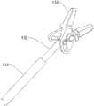
图1为本实用新型实施例提供的一种手术器械的结构示意图;Fig. 1 is a schematic structural view of a surgical instrument provided by an embodiment of the present invention;
图2为本实用新型实施例提供的夹持组件的结构示意图;Fig. 2 is a schematic structural view of the clamping assembly provided by the embodiment of the present invention;
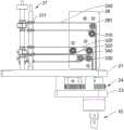
图3为本实用新型实施例提供的器械传动装置的结构示意图;Fig. 3 is a schematic structural diagram of an instrument transmission device provided by an embodiment of the present invention;
图4为本实用新型实施例提供的第一组驱动绳的走向示意图;Fig. 4 is a schematic diagram of the direction of the first group of driving ropes provided by the embodiment of the present invention;
图5为图4另一视角下的结构示意图;Fig. 5 is a schematic structural diagram of Fig. 4 under another viewing angle;
图6为本实用新型实施例提供的第二组驱动绳的走向示意图;Fig. 6 is a schematic diagram of the direction of the second group of driving ropes provided by the embodiment of the present invention;
图7为本实用新型实施例提供的基板、齿轮组、齿轮板及支撑柱相配合的结构示意图;Fig. 7 is a structural schematic diagram of the cooperation of the base plate, the gear set, the gear plate and the support column provided by the embodiment of the utility model;
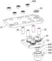
图8为图7的爆炸示意图;Fig. 8 is the explosion diagram of Fig. 7;
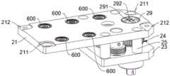
图9为本实用新型实施例提供的集线件的结构示意图;Fig. 9 is a schematic structural diagram of the wire collection provided by the embodiment of the present invention;
图10为本实用新型实施例提供的第一支柱的结构示意图;Fig. 10 is a schematic structural view of the first pillar provided by the embodiment of the present invention;
图11为本实用新型实施例提供的第二支柱的结构示意图;Fig. 11 is a schematic structural view of the second pillar provided by the embodiment of the present invention;
图12为本实用新型实施例提供的软杆驱动绳的走向示意图;Figure 12 is a schematic diagram of the direction of the soft rod driving rope provided by the embodiment of the present invention;
图13为图12另一视角下的结构示意图;Fig. 13 is a schematic structural diagram of Fig. 12 under another viewing angle;
图14为图12中A处的局部放大图。FIG. 14 is a partial enlarged view of A in FIG. 12 .
图标:1-手术器械;10-柔性器械;11-柔性轴;12-器械末端;13-夹持组件;131-操作管;132-操作杆;133-夹钳;20-器械传动装置;21-基板;211-第一安装部;212-第二安装部;22-顶板;23-齿轮板;24-齿轮组;25-支撑柱;26-固定板;261-导向轮;27-换向件;271-换向轮;28-软杆衔接部;29-集线件;291-第一过孔;292-第二过孔;200-驱动轴;210-第一驱动轴;220-第二驱动轴;230-第三驱动轴;240-第四驱动轴;250-软杆驱动轴;260-齿轮组驱动轴;300-驱动绳;310-第一驱动绳;320-第二驱动绳;330-第三驱动绳;340-第四驱动绳;350-第五驱动绳;360-第六驱动绳;370-第七驱动绳;380-第八驱动绳;390-软杆驱动绳;400-支柱;410-第一支柱;411-定位凸柱;420-第二支柱;401-螺纹孔;500-端块;510-轴承安装座;520-螺栓孔;600-轴承。Icons: 1-surgical instrument; 10-flexible instrument; 11-flexible shaft; 12-instrument end; 13-clamp assembly; 131-operating tube; 132-operating rod; 133-clamp; 20-instrument transmission; 21 -base plate; 211-first installation part; 212-second installation part; 22-top plate; 23-gear plate; 24-gear set; 25-support column; 26-fixed plate; 271-reversing wheel; 28-soft rod joint; 29-collection piece; 291-first through hole; 292-second through hole; 200-drive shaft; 210-first drive shaft; Two drive shafts; 230-the third drive shaft; 240-the fourth drive shaft; 250-soft rod drive shaft; 260-gear set drive shaft; 300-drive rope; 310-the first drive rope; ; 330-the third driving rope; 340-the fourth driving rope; 350-the fifth driving rope; 360-the sixth driving rope; 370-the seventh driving rope; 400-pillar; 410-first pillar; 411-positioning boss; 420-second pillar; 401-threaded hole; 500-end block; 510-bearing mounting seat; 520-bolt hole; 600-bearing.
具体实施方式Detailed ways
为使本实用新型实施例的目的、技术方案和优点更加清楚,下面将结合本实用新型实施例中的附图,对本实用新型实施例中的技术方案进行清楚、完整地描述,显然,所描述的实施例是本实用新型一部分实施例,而不是全部的实施例。通常在此处附图中描述和示出的本实用新型实施例的组件可以以各种不同的配置来布置和设计。In order to make the purpose, technical solutions and advantages of the embodiments of the utility model more clear, the technical solutions in the embodiments of the utility model will be clearly and completely described below in conjunction with the accompanying drawings in the embodiments of the utility model. Obviously, the described The embodiments are some embodiments of the present utility model, but not all embodiments. The components of the embodiments of the invention generally described and illustrated in the figures herein may be arranged and designed in a variety of different configurations.
因此,以下对在附图中提供的本实用新型的实施例的详细描述并非旨在限制要求保护的本实用新型的范围,而是仅仅表示本实用新型的选定实施例。基于本实用新型中的实施例,本领域普通技术人员在没有作出创造性劳动前提下所获得的所有其他实施例,都属于本实用新型保护的范围。Therefore, the following detailed description of the embodiments of the present invention provided in the accompanying drawings is not intended to limit the scope of the claimed invention, but merely represents selected embodiments of the present invention. Based on the embodiments of the present utility model, all other embodiments obtained by persons of ordinary skill in the art without making creative efforts belong to the scope of protection of the present utility model.
应注意到:相似的标号和字母在下面的附图中表示类似项,因此,一旦某一项在一个附图中被定义,则在随后的附图中不需要对其进行进一步定义和解释。It should be noted that like numerals and letters denote similar items in the following figures, therefore, once an item is defined in one figure, it does not require further definition and explanation in subsequent figures.
在本实用新型的描述中,需要说明的是,术语“中心”、“上”、“下”、“左”、“右”、“竖直”、“水平”、“内”、“外”等指示的方位或位置关系为基于附图所示的方位或位置关系,或者是该实用新型产品使用时惯常摆放的方位或位置关系,仅是为了便于描述本实用新型和简化描述,而不是指示或暗示所指的装置或元件必须具有特定的方位、以特定的方位构造和操作,因此不能理解为对本实用新型的限制。此外,术语“第一”、“第二”、“第三”等仅用于区分描述,而不能理解为指示或暗示相对重要性。In the description of the present utility model, it should be noted that the terms "center", "upper", "lower", "left", "right", "vertical", "horizontal", "inner", "outer" The orientation or positional relationship indicated by etc. is based on the orientation or positional relationship shown in the drawings, or the orientation or positional relationship that is usually placed when the product of the utility model is used. It is only for the convenience of describing the utility model and simplifying the description, rather than Any indication or implication that a referenced device or element must have a particular orientation, be constructed, and operate in a particular orientation should not be construed as limiting the invention. In addition, the terms "first", "second", "third", etc. are only used for distinguishing descriptions, and should not be construed as indicating or implying relative importance.
此外,术语“水平”、“竖直”等术语并不表示要求部件绝对水平或悬垂,而是可以稍微倾斜。如“水平”仅仅是指其方向相对“竖直”而言更加水平,并不是表示该结构一定要完全水平,而是可以稍微倾斜。Furthermore, the terms "horizontal", "vertical" and the like do not imply that a component is absolutely level or overhanging, but may be slightly inclined. For example, "horizontal" only means that its direction is more horizontal than "vertical", and it does not mean that the structure must be completely horizontal, but can be slightly inclined.
在本实用新型的描述中,还需要说明的是,除非另有明确的规定和限定,术语“设置”、“安装”、“相连”、“连接”应做广义理解,例如,可以是固定连接,也可以是可拆卸连接,或一体地连接;可以是机械连接,也可以是电连接;可以是直接相连,也可以通过中间媒介间接相连,可以是两个元件内部的连通。对于本领域的普通技术人员而言,可以具体情况理解上述术语在本实用新型中的具体含义。In the description of the present utility model, it should also be noted that, unless otherwise specified and limited, the terms "setting", "installation", "connection" and "connection" should be understood in a broad sense, for example, it can be a fixed connection , can also be detachably connected, or integrally connected; can be mechanically connected, can also be electrically connected; can be directly connected, can also be indirectly connected through an intermediary, and can be internal communication between two components. Those of ordinary skill in the art can understand the specific meanings of the above terms in the present utility model in specific situations.
在现有的柔性手术器械的器械传动装置中,例如现有技术(CN106308939B)公开的一种用于驱动柔性连续体结构的驱动单元,其中的驱动单元可以理解为器械传动装置,其中结构骨驱动机构通过协同推动驱动构节结构骨实现驱动构节向任意方向的弯转运动,从而实现近端结构体向相同方向的弯转运动,最终实现柔性连续体结构的远端结构体进行弯转运动。但其在驱动过程中,主要通过滑轮组的配合来驱动绕过其中的结构骨,但在滑轮组与结构骨的包角不大的时候,容易出现结构骨与滑轮组打滑的情况,从而导致控制精度不高,而滑轮组与结构骨的包角较大时会导致结构骨与滑轮组之间的摩擦力大而出现驱动困难的情况。In the instrument transmission device of the existing flexible surgical instrument, for example, a drive unit for driving a flexible continuum structure disclosed in the prior art (CN106308939B), the drive unit can be understood as an instrument transmission device, in which the structural bone drives The mechanism realizes the bending motion of the driving segment in any direction by cooperatively pushing the driving segment structure bone, thereby realizing the bending motion of the proximal structure in the same direction, and finally realizing the bending motion of the distal structure of the flexible continuum structure . However, in the driving process, the structural bone is mainly driven by the cooperation of the pulley block, but when the wrapping angle between the pulley block and the structural bone is not large, the structural bone and the pulley block are prone to slipping, resulting in poor control accuracy. If the angle between the pulley block and the structural bone is large, the friction between the structural bone and the pulley block will be large and the driving will be difficult.
下面结合专利附图详细介绍本实用新型实施例提供的一种器械传动装置的具体结构及其带来相应的技术效果。The specific structure of an instrument transmission device provided by the embodiment of the present invention and the corresponding technical effects brought by it will be described in detail below in conjunction with the attached drawings of the patent.
本实施例提供了一种手术机器人(图未示),手术机器人包括相连接的主控台(图未示)和操作手(图未示),其中操作手可拆卸的装配有手术器,械,手术器械1用于进行微创手术作业。This embodiment provides a surgical robot (not shown in the figure), the surgical robot includes a connected main console (not shown in the figure) and an operating hand (not shown in the figure), wherein the operating hand is detachably equipped with a surgical instrument, the instrument , the
进一步的,请参考图1-图2,手术器械1包括相连接的柔性器械10及器械传动装置20。Further, please refer to FIGS. 1-2 , the
其中柔性器械10包括相连接的柔性轴11以及器械末端12,其中器械末端12位于柔性轴11远离器械传动装置20的一侧,需要说明的,柔性器械10大多通过器械传动装置20中的传动件驱动与自身连接的驱动绳300实现自身的弯曲运动。此为本领域的常规手段,在此不再赘述。The
需要说明的是,其中器械末端12远离柔性轴11的一端设置有夹持组件13,夹持组件13包括操作管131、操作杆132及夹钳133,操作管131套设在操作杆132的外部,操作杆132设置于柔性轴11及器械末端12的内部,夹钳133设置于操作杆132的伸出器械末端12的端部。It should be noted that the end of the
通过带动操作杆132相对操作管131伸缩,即可实现夹钳133的开合动作,从而完成微创手术作业操作。操作杆132可以是软杆,操作管131可以是软管,以便于操作杆132和操作管131产生一定形变,而套设在操作杆132外的操作管131可减小操作管131在伸缩过程中产生的摩擦力,以及为操作杆132提供支撑推力。By driving the
请继续参考图3-图5,本实用新型实施例提供的一种器械传动装置20包括基板21、多根驱动轴200及多根驱动绳300。Please continue to refer to FIGS. 3-5 , an instrument transmission device 20 provided by an embodiment of the present invention includes a
其中多根驱动轴200设置于基板21且能相对基板21沿自身轴线转动,驱动绳300的至少一端部用于绕接于驱动轴200且驱动绳300用于与柔性器械10连接,驱动绳300用于在驱动轴200的带动下驱动柔性器械10弯曲。Wherein a plurality of driving
容易理解的,驱动绳300绕接在驱动轴200时,驱动轴200在转动时,能够带动绕接于驱动轴200上的驱动绳300松散或绕紧,进而实现带动柔性器械10进行弯转运动。驱动绳300绕接于驱动轴200上,本实施例中通过驱动轴200直接驱动与柔性器械10连接的驱动绳300,能够避免出现打滑以及大摩擦的情况,进而有效提高本实用新型提供的器械传动装置20的控制精度,也能够避免通过中间部件也即滑轮组的情况来进行传动,在一定程度上减少了空间占用。It is easy to understand that when the driving
进一步的,在本实施例中,多根驱动绳300包括第一组驱动绳300与第二组驱动绳300,第一组驱动绳300包括第一驱动绳310、第二驱动绳320、第三驱动绳330及第四驱动绳340,且第一驱动绳310、第二驱动绳320、第三驱动绳330及第四驱动绳340均具有两个分别绕接两个驱动轴200的自由端却两个自由端分别绕接于两个驱动轴200的绕设方向相反。Further, in this embodiment, the multiple driving
需要说明的是,本实施例中的第一驱动绳310、第二驱动绳320、第三驱动绳330及第四驱动绳340中的任意一个在绕接时,以第一驱动绳310为例,第一驱动绳310的两个自由端分别穿设于柔性器械10并绕接与两个不同的驱动轴200上,并且第一驱动绳310两个端部之间的预设部位固定连接在柔性器械10上。由于第一驱动绳310的两个自由端以相反的绕接方向分别绕接两个不同的驱动轴200上,因此在控制时,其中一个驱动轴200上的驱动绳300的长度伸长时,另一个驱动轴200上的驱动绳300长度缩短。It should be noted that, when winding any one of the
需要说明的是,驱动绳300的长度可以理解绕接于驱动轴200上的驱动绳300到与柔性器械10连接处的绳长。因此通过上述设置能够保证在驱动轴200的转动下顺利的控制柔性器械10的弯曲。其中弯曲包括本领域中的俯仰运动及偏航运动。It should be noted that the length of the driving
请继续参考图3-图5,进一步的,在本实施例中,多根驱动轴200包括第一驱动轴210及第二驱动轴220,第一驱动绳310的两个自由端、第二驱动绳320的两个自由端、第三驱动绳330的两个自由端及第四驱动绳340的分别绕接于第一驱动轴210及第二驱动轴220。可以理解的,其中第一驱动绳310、第二驱动绳320、第三驱动绳330及第四驱动绳340的两个自由端均分别绕接于第一驱动轴210与第二驱动轴220上。通过两根驱动轴200控制四根驱动绳300,以带动柔性器械10进行弯曲。Please continue to refer to Fig. 3-Fig. 5, further, in this embodiment, a plurality of driving
需要说明的是,在实际连接中,其中第一驱动绳310与第二驱动绳320可以组合为第一驱动组,第三驱动绳330与第四驱动绳340可以组合为第二驱动组,分别控制柔性器械10中不同位置的弯曲,例如,第一驱动绳310与第二驱动绳320连接到柔性器械10中最末端的关节,可以理解为上述的器械末端12,进而通过第一驱动轴210及第二驱动轴220驱动第一驱动绳310与第二驱动绳320实现器械末端12的弯曲运动。第三驱动绳330与第四驱动绳340连接到次末端的关节,该次末端可以理解为柔性轴11上的某处关节,其中具体位置可以根据具体情况具体设置。It should be noted that, in the actual connection, the
通过第一驱动轴210与第二驱动轴220驱动第一驱动绳310、第二驱动绳320、第三驱动绳330及第四驱动绳340以实现柔性器械10的弯曲运动。用两根轴控制四根驱动绳300,节约了基板21上的空间,进而也减少了器械传动装置20的空间占用。The
具体的,在本实施例中,对于第一驱动轴210或第二驱动轴220上的第一驱动绳310,第二驱动轴220、第三驱动绳330及第四驱动绳340,第一驱动绳310的绕接方向与第三驱动绳330的绕接方向相同且与第二驱动绳320及第四驱动绳340的绕接方向相反。Specifically, in this embodiment, for the
换句话说,以第一驱动轴210为例,其中第一驱动绳310的绕接方向与第三驱动绳330的绕接方向相同,第二驱动绳320与第四驱动绳340的绕接方向相同,并且第一驱动绳310的绕接方向与第二驱动绳320的绕接方向相反。因此当第一驱动绳310与第三驱动绳330的长度伸长时,第二驱动绳320与第四驱动绳340的缩短。In other words, taking the first driving shaft 210 as an example, the winding direction of the
进一步的,在本实施例中,第一驱动轴210上的第一驱动绳310、第二驱动绳320、第三驱动绳330及第四驱动绳340的绕接位置间隔设置。同样的、第二驱动轴220上的第一驱动绳310、第二驱动绳320、第三驱动绳330及第四驱动绳340的绕接位置间隔设置,以保证第一驱动绳310、第二驱动绳320、第三驱动绳330及第四驱动绳340之间互不干涉。Further, in this embodiment, the winding positions of the
请参考图3及图6,进一步的,在本实施例中,第二组驱动绳300还包括第五驱动绳350、第六驱动绳360、第七驱动绳370及第八驱动绳380,第五驱动绳350、第六驱动绳360、第七驱动绳370及第八驱动绳380的一端用于绕接驱动轴200,另一端用于与柔性器械10连接,第五驱动绳350及第六驱动绳360绕接方向分别与第七驱动绳370及第八驱动绳380的绕接方向相反。Please refer to FIG. 3 and FIG. 6 , further, in this embodiment, the second group of driving
需要说明的是,本实施例中的第五驱动绳350与第六驱动绳360能够与第七驱动绳370及第八驱动绳380在共同作用下,以实现柔性器械10进行弯曲运动。It should be noted that the
进一步的,多根驱动轴200还包括第三驱动轴230及第四驱动轴240,其中第五驱动绳350与第六驱动绳360均绕设于第三驱动轴230且绕设方向相反,第七驱动绳370与第八驱动绳380均绕设于第四驱动轴240且绕设方向相反。Further, the plurality of driving
需要说明的是,在本实施例中,其中第五驱动绳350、第六驱动绳360、第七驱动绳370及第八驱动绳380均连接于柔性轴11的同一关节处,并且第五驱动轴200、第六驱动轴200、第七驱动轴200及第八驱动轴200关于柔性轴11中过轴线对称设置。需要说明的是,上述的轴线为当柔性轴11未出弯曲状态时的轴线。It should be noted that, in this embodiment, the
可以理解的,用于能够灵活的通过控制第三驱动轴230及第四驱动轴240的转动控制柔性轴11的弯曲运动。It can be understood that the bending movement of the
因此,能够通过第三驱动轴230与第四驱动轴240两个轴驱动第五驱动绳350、第六驱动绳360、第七驱动绳370及第八驱动绳380。两根轴控制四根驱动绳300,节约了基板21上的空间,进而也减少了器械传动装置20的空间占用。Therefore, the
请继续参考图3-图6,进一步的,在本实施例中,器械传动装置20还包括设置于基板21上的固定板26及多个换向件27,固定板26设置有多个导向轮261,导向轮261能相对固定板26沿自身轴线转动,每个驱动绳300沿预设路径经过导向轮261及换向件27并绕设于驱动轴200。Please continue to refer to Fig. 3-Fig. 6, further, in this embodiment, the instrument transmission device 20 also includes a fixed
具体的,换向件27包括换向柱以及沿换向柱轴线方向依次套设于换向柱上的多个换向轮271,其中换向轮271能相对换向柱沿自身轴线转动。可以理解的,驱动绳300沿预设路径经过导向轮261及换向轮271并绕设与驱动轴200。Specifically, the reversing
其中换向件27的数量为四个,其中包括第一换向件27、第二换向件27、第三换向件27及第四换向件27,其中第一换向件27的换向柱及第二换向件27的换向柱上均设置有四个换向轮271,第三换向件27的换向柱及第四换向件27的换向柱上均设置有两个换向轮271。Wherein the quantity of the reversing
需要说明的是,在本实施例中,第一驱动轴210、第二驱动轴220、第三驱动轴230及第四驱动轴240在基板21上呈矩形阵列排布,第一换向件27、第二换向件27、第三换向件27及第四换向件27在基板21上呈矩形阵列排布,以保证各个驱动绳300的走线以及基板21上驱动轴200的排布和换向件27的排布更加美观。It should be noted that, in this embodiment, the first drive shaft 210, the
需要说明的是,在另外的一些其它实施例中,驱动轴200及驱动绳300的数量并不仅限于上述的数量,其还可以根据具体情况设计不同数量的驱动轴200及驱动绳300,在此对驱动轴200与驱动绳300的数量不做限定。It should be noted that, in other other embodiments, the number of
容易理解的,第一驱动绳310、第二驱动绳320、第三驱动绳330及第四驱动绳340供八个自由端分别经过固定板26上的导向轮261以及第一换向件27与第二换向件27上的换向轮271,进而与第一驱动轴210及第二驱动轴220绕接。It is easy to understand that the eight free ends of the
第五驱动绳350、第六驱动绳360、第七驱动绳370及第八驱动绳380共四个自由端能够沿预设路径经过导向轮261及第三换向件27与第四换向件27的换向轮271。A total of four free ends of the
可以理解的,通过导向轮261与换向轮271的设置,能够保证驱动绳300能够更加稳定的绕接在驱动轴200上。It can be understood that, through the setting of the
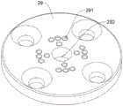
请参考图1、图7-图9,进一步的,在本实施例中,器械传动装置20还包括集线件29,其中基板21开设有用于安装集线件29的贯通孔,集线件29开设有供驱动绳300穿设的多个第一过孔291,集线件29还开设有供柔性器械10的软杆穿设的第二过孔292。集线件29能够使得驱动绳300按照预期进入基板21,并且还能够在第一过孔291的作用下防止多个驱动绳300之间产生干涉,进而能够保证器械传动装置20的传动效果以及控制精度。Please refer to FIG. 1, FIG. 7-FIG. 9, further, in this embodiment, the instrument transmission device 20 also includes a
需要说明的是,其中安装集线件29的贯通孔为阶梯孔,且台阶处设置有供紧固件连接的孔,集线件29也设置有供紧固件连接的孔。具体的,集线件29与基板21的呈阶梯状的贯通孔通过紧固件可拆卸连接。It should be noted that the through hole for installing the
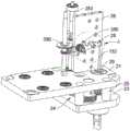
请继续参考图1、图7-图8,进一步的,在本实施例中,器械传动装置20还包括顶板22、齿轮板23、支撑柱25、齿轮组驱动轴260及位于基板21与齿轮板23之间的齿轮组24。Please continue to refer to Fig. 1, Fig. 7-Fig. 8, further, in this embodiment, the instrument transmission device 20 also includes a
具体的,其中支撑柱25的两端分别与齿轮板23及基板21连接,以与齿轮板23和基板21之间共同限定出供齿轮组24安装的空间。Specifically, the two ends of the
其中齿轮组驱动轴260穿设于基板21且齿轮组驱动轴260的一端与齿轮板23转动连接,齿轮组驱动轴260能相对基板21及齿轮板23绕自身轴线转动,齿轮组24中的主动齿轮套设于齿轮组驱动轴260上,其中齿轮组24中具有与柔性轴11连接且同心的从动齿轮,因此,在齿轮组驱动轴260的带动下,能够带动齿轮组24转动,进而带动柔性轴11整体的旋转。Wherein the gear set driving
上述的第一驱动轴210、第二驱动轴220、第三驱动轴230、第四驱动轴240、齿轮组驱动轴260及软杆驱动轴250的另一端穿设于顶板22且能够相对顶板22沿自身轴线转动。可以理解的,可以在顶板22上设置用于驱动第一驱动轴210、第二驱动轴220、第三驱动轴230、第四驱动轴240、齿轮组驱动轴260及软杆驱动轴250的动力装置以带动第一驱动轴210、第二驱动轴220、第三驱动轴230、第四驱动轴240、齿轮组驱动轴260及软杆驱动轴250转动。The other ends of the first drive shaft 210 , the
具体的,在本实施例中,基板21通过轴承600与第一驱动轴210、第二驱动轴220、第三驱动轴230、第四驱动轴240及软杆驱动轴250的一端连接。顶板22通过轴承600与第一驱动轴210、第二驱动轴220、第三驱动轴230、第四驱动轴240、齿轮组驱动轴260及软杆驱动轴250的另一端连接。Specifically, in this embodiment, the
第一换向件27、第二换向件27、第三换向件27、第四换向件27及固定板26均位于基板21与顶板22之间。The first reversing
请参考图8,具体的,其中齿轮板23远离齿轮组24的一端设置有与齿轮组24中齿轮相对应的轴承600,其中轴承600与齿轮组24中齿轮的齿轮轴连接。进一步的,器械传动装置20还包括端块500,端块500设置有与轴承600连接的轴承安装座510且轴承安装座510开设有供柔性轴11连接通孔,端块500还设置有用于与齿轮板23螺纹连接的螺栓孔520。Please refer to FIG. 8 , specifically, the end of the
可以理解的,柔性器械10的柔性轴11远离器械末端12的一端穿过端块500的通孔与轴承600连接,在齿轮驱动轴200的带动下,能够带动齿轮组24转动,进而带动柔性轴11整体的旋转。It can be understood that the end of the
请参考图1及图10-图11,请参考图进一步的,柔性器械10还设置有支柱400,其中支柱400的两端分别与基板21与顶板22连接。具体的,在本实施例中,基板21为矩形板,且基板21的四角均设置有供支柱400连接的安装部,其中基板21具有一经过自身对角线的两个第一安装部211及两个第二安装部212。其中第一安装部211开设有台阶孔,同样的,支柱400分为第一支柱410与第二支柱420,第一支柱410与第一安装部211连接,第二支柱420与第二安装部212连接。第一支柱410靠近基板21的一端设置有定位凸柱411,其中定位凸柱411用于与台阶孔配合,且第一支柱410靠近顶板22的一端与凸柱开设有螺纹孔401,第二支柱420的端部也开设有螺纹孔401。可以理解的,第一支柱410通过凸柱与第一安装部211的阶梯孔配合能够保证第一支柱410能够精准安装,保证安装的稳定性。Please refer to FIG. 1 and FIG. 10-FIG. 11 , please refer to the figure further, the
可以理解的,其中第一支柱410的两端分别与顶板22与基板21通过螺栓螺纹连接,第二支柱420的两端分别与顶板22与基板21通过螺栓螺纹连接。当然在另外的一些实施例中,第一支柱410与第二支柱420还可以通过其它的方式与顶板22与基板21连接,在此对其不做限定。It can be understood that the two ends of the
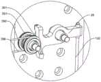
请参考图12-图14,进一步的,在本实施例中,器械传动装置20还包括软杆衔接部28及软杆驱动绳390,软杆衔接部28可转动的设置于固定板26且转动轴线与固定板26垂直,软杆衔接部28的一端用于与软杆连接,软杆衔接部28的另一端用于与软杆驱动绳390连接。可以理解的,由于软杆衔接部28能够相对固定板26转动,因此当软杆与软杆驱动绳390分别与软杆衔接部28的两端连接时,在软杆驱动绳390的带动下,能够使得软杆衔接部28连接有软杆的一端进行上下运动,进而实现夹钳133的开合运动。Please refer to Fig. 12-Fig. 14, further, in this embodiment, the instrument transmission device 20 also includes a soft
可以理解的,通过上述设置,便于运动方程的技术,并且能够通过软杆驱动轴250精准的控制软杆衔接部28转动,进而实现软杆的上下驱动,从而精确的控制器械末端12的夹钳133的开合运动。It can be understood that, through the above-mentioned setting, it is convenient for the technology of the equation of motion, and can accurately control the rotation of the soft
进一步的,在本实施例中,器械传动装置20还包括软杆驱动轴250,软杆驱动绳390远离软杆衔接部28的一端绕接于软杆驱动轴250,软杆驱动轴250设置于基板21且能够相对基板21沿自身轴线转动。Further, in this embodiment, the instrument transmission device 20 also includes a soft
具体的,在本实施例中,其中软杆衔接部28远离软杆的一端设置有第一连接部及第二连接部,其中第一连接部与第二连接部沿软杆驱动轴250的轴线方向排布,软杆驱动绳390的数量为两个,两个驱动绳300分别与第一连接部与第二连接部连接。其中两个软杆驱动绳390绕接于软杆驱动轴250上的绕接方向相反。在本实施例中,两个软杆驱动绳390能够通过导向轮261进而以不同的绕接方向绕接于软杆驱动轴250。Specifically, in this embodiment, the end of the soft
可以理解的,两个软杆驱动绳390通过不同的方向绕接在软杆驱动轴250上,其中一个伸长时,另外一个缩短。两个软杆驱动绳390相互配合,能够保证驱动软杆的稳定性。It can be understood that the two soft
可以理解的,当转动软杆驱动轴250时,能够带动绕接于软杆驱动轴250上的软杆驱动绳390伸缩,以带动软杆的上下运动,进而实现夹钳133的开合运动。It can be understood that when the soft
综上所述,本实用新型实施例提供的一种器械传动装置20、手术器械1及手术机器人。其中手术机器人包括主控台、操作手以及手术器械1,主控台与操作手连接,操作手与手术器械1可拆卸连接,手术器械1用于进行微创手术作业,手术器械1包括相连接的柔性器械10及器械传动装置20。其中器械传动装置20包括基板21、多根驱动轴200及多根驱动绳300。其中多根驱动轴200设置于基板21且能相对基板21沿自身轴线转动,驱动绳300的至少一端部用于绕接于驱动轴200且驱动绳300用于与柔性器械10连接,驱动绳300用于在驱动轴200的带动下驱动柔性器械10弯曲。驱动绳300绕接在驱动轴200时,驱动轴200在转动时,能够带动绕接于驱动轴200上的驱动绳300松散或绕紧,进而实现带动柔性器械10进行弯转运动。驱动绳300绕接于驱动轴200上,本实施例中通过驱动轴200直接驱动与柔性器械10连接的驱动绳300,能够避免出现打滑以及大摩擦的情况,进而有效提高本实用新型提供的器械传动装置20的控制精度。In summary, the embodiment of the present invention provides an instrument transmission device 20 , a
以上所述仅为本实用新型的优选实施例而已,并不用于限制本实用新型,对于本领域的技术人员来说,本实用新型可以有各种更改和变化。凡在本实用新型的精神和原则之内,所作的任何修改、等同替换、改进等,均应包含在本实用新型的保护范围之内。The above descriptions are only preferred embodiments of the utility model, and are not intended to limit the utility model. For those skilled in the art, the utility model can have various modifications and changes. Any modification, equivalent replacement, improvement, etc. made within the spirit and principles of the present utility model shall be included in the protection scope of the present utility model.
Claims (12)
Translated fromChinesePriority Applications (1)
| Application Number | Priority Date | Filing Date | Title |
|---|---|---|---|
| CN202320351778.1UCN219070434U (en) | 2023-02-23 | 2023-02-23 | Instrument transmission device, surgical instrument and surgical robot |
Applications Claiming Priority (1)
| Application Number | Priority Date | Filing Date | Title |
|---|---|---|---|
| CN202320351778.1UCN219070434U (en) | 2023-02-23 | 2023-02-23 | Instrument transmission device, surgical instrument and surgical robot |
Publications (1)
| Publication Number | Publication Date |
|---|---|
| CN219070434Utrue CN219070434U (en) | 2023-05-26 |
Family
ID=86394286
Family Applications (1)
| Application Number | Title | Priority Date | Filing Date |
|---|---|---|---|
| CN202320351778.1UActiveCN219070434U (en) | 2023-02-23 | 2023-02-23 | Instrument transmission device, surgical instrument and surgical robot |
Country Status (1)
| Country | Link |
|---|---|
| CN (1) | CN219070434U (en) |
Cited By (1)
| Publication number | Priority date | Publication date | Assignee | Title |
|---|---|---|---|---|
| CN116158864A (en)* | 2023-02-23 | 2023-05-26 | 杭州唯精医疗机器人有限公司 | Instrument transmission device, surgical instrument and surgical robot |
- 2023
- 2023-02-23CNCN202320351778.1Upatent/CN219070434U/enactiveActive
Cited By (1)
| Publication number | Priority date | Publication date | Assignee | Title |
|---|---|---|---|---|
| CN116158864A (en)* | 2023-02-23 | 2023-05-26 | 杭州唯精医疗机器人有限公司 | Instrument transmission device, surgical instrument and surgical robot |
Similar Documents
| Publication | Publication Date | Title |
|---|---|---|
| CN104116547B (en) | The little inertia operating theater instruments of low friction for micro-wound operation robot | |
| US6371952B1 (en) | Articulated surgical instrument for performing minimally invasive surgery with enhanced dexterity and sensitivity | |
| CN111437036A (en) | Serpentine surgical robot applied to minimally invasive surgery | |
| CN110179543A (en) | A laparoscopic surgery robot | |
| US20130304084A1 (en) | Mechanical manipulator for surgical instruments | |
| US9227326B2 (en) | Remote center of motion mechanism and method of use | |
| EP4173576A1 (en) | Continuous body instrument and surgical robot | |
| WO2020010759A1 (en) | Minimally invasive surgical instrument with driving single-side plate arrangement | |
| CN219070434U (en) | Instrument transmission device, surgical instrument and surgical robot | |
| CN109009453A (en) | Intervene the force feedback type main manipulator of robot | |
| CN111407412A (en) | Natural cavity operation end manipulator | |
| WO2023160488A1 (en) | Mechanical arm and medical trolley | |
| EP4173588B1 (en) | Continuum instrument and surgical robot | |
| CN115605139B (en) | Continuum instrument and surgical robot | |
| US20230225806A1 (en) | Continuum instrument and surgical robot | |
| CN114683314A (en) | Arm joint, arm and surgical robot | |
| CN112545435A (en) | Modular multi-wire driving continuum lens arm based on fixed pulleys | |
| WO2021155704A1 (en) | Operation arm and surgical robot | |
| CN210228310U (en) | Laparoscopic surgery robot | |
| WO2023160486A1 (en) | End articulated arm, robotic arm, and medical cart | |
| CN118986478B (en) | Multi-degree-of-freedom minimally invasive surgical instruments | |
| Wu et al. | Design, control, and experiments of a novel robotic uterine manipulator with the motorized 3-DoF manipulation rod | |
| CN110711032A (en) | A miniaturized surgical robot with a rear motor | |
| CN219940788U (en) | Small arm structure for minimally invasive surgical robots | |
| CN219147918U (en) | Flexible joint, surgical instrument and surgical robot |
Legal Events
| Date | Code | Title | Description |
|---|---|---|---|
| GR01 | Patent grant | ||
| GR01 | Patent grant | ||
| CP03 | Change of name, title or address | Address after:311121 Hangzhou City, Yuhang District, Yuhang Street, Keji Avenue 39, Building 1, first floor, Building 2, first to fourth floors Patentee after:Hangzhou Kangji Weijing Medical Robot Co.,Ltd. Country or region after:China Address before:Building 1, 1st Floor, and Building 2, 1-4 Floors, No. 39 Keji Avenue, Yuhang Street, Yuhang District, Hangzhou City, Zhejiang Province Patentee before:Hangzhou Weijing medical robot Co.,Ltd. Country or region before:China | |
| CP03 | Change of name, title or address |