CN219048726U - Urethral forceps for endoscope - Google Patents
Urethral forceps for endoscopeDownload PDFInfo
- Publication number
- CN219048726U CN219048726UCN202220606025.6UCN202220606025UCN219048726UCN 219048726 UCN219048726 UCN 219048726UCN 202220606025 UCN202220606025 UCN 202220606025UCN 219048726 UCN219048726 UCN 219048726U
- Authority
- CN
- China
- Prior art keywords
- sleeve
- pliers
- forceps
- push handle
- handle
- Prior art date
- Legal status (The legal status is an assumption and is not a legal conclusion. Google has not performed a legal analysis and makes no representation as to the accuracy of the status listed.)
- Expired - Fee Related
Links
- 230000007480spreadingEffects0.000claimsabstractdescription8
- 230000007246mechanismEffects0.000claimsdescription7
- 210000003708urethraAnatomy0.000abstractdescription15
- 238000002357laparoscopic surgeryMethods0.000abstractdescription3
- 210000000080chela (arthropods)Anatomy0.000description9
- 210000001519tissueAnatomy0.000description6
- 230000009471actionEffects0.000description4
- 238000000034methodMethods0.000description4
- 238000010586diagramMethods0.000description3
- 230000008569processEffects0.000description3
- 206010060862Prostate cancerDiseases0.000description2
- 208000000236Prostatic NeoplasmsDiseases0.000description2
- 230000009286beneficial effectEffects0.000description1
- 230000000694effectsEffects0.000description1
- 238000012986modificationMethods0.000description1
- 230000004048modificationEffects0.000description1
- 238000001356surgical procedureMethods0.000description1
Images

Landscapes
- Endoscopes (AREA)
Abstract
Translated fromChinese
Description
Translated fromChinese技术领域technical field
本实用新型涉及医疗器械技术领域,具体涉及一种腔镜用尿道钳。The utility model relates to the technical field of medical instruments, in particular to a urethral forceps for laparoscopy.
背景技术Background technique
目前,前列腺癌发病率越来越高,腹腔镜下前列腺癌手术越来越多,在手术中需要钳夹尿道使其暴露,以便后续的手术操作。传统的尿道钳容易对人体造成损伤,且使用起来往往会出现滑脱等情况,还可能需要会阴部顶等器材,操作十分麻烦,给医务人员增加了工作难度;在夹持尿道的过程中,医生需要持续对尿道钳的钳柄施加压力才能持续夹持尿道,不利于手术的操作;并且在夹持尿道时,尿道与其他组织距离较近,在夹持过程中容易连带夹持周围的组织,不利于手术操作。At present, the incidence of prostate cancer is increasing, and there are more and more laparoscopic prostate cancer operations. During the operation, the urethra needs to be clamped to expose it for subsequent operations. Traditional urethral clamps are easy to cause damage to the human body, and often slip when used, and may require perineal tops and other equipment, which is very troublesome to operate and increases the difficulty of work for medical staff; in the process of clamping the urethra, the doctor It is necessary to continuously apply pressure to the handle of the urethral forceps to continue to clamp the urethra, which is not conducive to the operation of the operation; and when clamping the urethra, the distance between the urethra and other tissues is relatively close, and it is easy to clamp the surrounding tissues during the clamping process. Not conducive to surgery.
实用新型内容Utility model content
本实用新型为了解决上述问题,设计了一种腔镜用尿道钳,能够将尿道周围的组织撑开后再进行夹持,避免夹持周围组织,便于手术的进行。In order to solve the above problems, the utility model designs a urethral forceps for laparoscopy, which can clamp the tissues around the urethra after stretching, avoid clamping the surrounding tissues, and facilitate the operation.
为了解决上述技术问题并达到上述技术效果,本实用新型通过以下技术内容实现的:In order to solve the above-mentioned technical problems and achieve the above-mentioned technical effects, the utility model is realized through the following technical contents:
一种腔镜用尿道钳,包括钳套、钳柄、推柄、主套管、副套管、套杆、撑开钳、夹持钳;所述钳套内部中空,钳套的底部设有滑槽,钳套的首端上转动设有与钳套连通的螺套;所述钳柄与钳套的底部连接,钳柄上设有滑孔,滑孔内设有第一弹簧;所述推柄的一端穿过滑槽位于钳套内,推柄上设有推柱,推柱滑动设置在滑孔内;所述主套管为两端开口的空心圆柱体,主套管的首端与钳套的尾端连通;所述副套管为两端开口的空心圆柱体,副套管设置在主套管内,副套管的首端穿过钳套内部与螺套螺纹连接,副套管位于钳套内部的底端上设有通槽;所述套杆设置在副套管内;所述推柄位于钳套内的端头穿过通槽与套杆连接;所述撑开钳、夹持钳均包括左钳、右钳,撑开钳、夹持钳上的左钳、右钳分别铰接在副套管、套杆的端头并在左钳、右钳与副套管、套杆之间分别设有扭簧。A kind of urethral forceps for laparoscope, comprising forceps cover, forceps handle, push handle, main casing, secondary casing, sleeve rod, spreading forceps, clamping forceps; The inside of described forceps is hollow, and the bottom of forceps is provided with A chute, the first end of the pliers sleeve is rotated to be provided with a screw sleeve connected with the pliers cover; the pliers handle is connected to the bottom of the pliers cover, and a slide hole is provided on the pliers handle, and a first spring is arranged in the slide hole; One end of the push handle passes through the chute and is located in the clamp sleeve. The push handle is provided with a push column, which is slidably arranged in the slide hole; the main sleeve is a hollow cylinder with two ends open, and the head end of the main sleeve It communicates with the tail end of the pliers sleeve; the auxiliary sleeve is a hollow cylinder with openings at both ends. A through groove is provided on the bottom end of the pipe located inside the pliers sleeve; the sleeve rod is arranged in the secondary casing; the end of the push handle located in the pliers sleeve is connected to the sleeve rod through the through groove; the spreader pliers, Clamping pliers all include left pliers and right pliers, the left pliers and right pliers on the spreading pliers and clamping pliers are respectively hinged on the ends of the auxiliary casing and the sleeve rod and connected between the left pliers, the right pliers and the auxiliary casing, the sleeve Torsion springs are respectively arranged between the rods.
进一步的,所述滑槽与通槽的长度一致,通槽位于滑槽的正上方。Further, the length of the chute is consistent with that of the through groove, and the through groove is located directly above the chute.
进一步的,还包括固定机构;所述固定机构包括按钮、U形卡块、第二弹簧、第一卡齿、第二卡齿;所述按钮滑动设置在钳套上,U形卡块设置在钳套内部,U形卡块的一端与按钮连接,U形卡块将推柄位于钳套内部的端头包裹在内部,第二弹簧设置在按钮对侧的钳套内壁上,第一卡齿倾斜设置在U形卡块的内壁上,第二卡齿设置在推柄位于U形卡块内的外壁上,第一卡齿与第二卡齿对应设置。Further, it also includes a fixing mechanism; the fixing mechanism includes a button, a U-shaped block, a second spring, a first locking tooth, and a second locking tooth; the button is slidably arranged on the pliers sleeve, and the U-shaped locking block is arranged on the Inside the pliers, one end of the U-shaped block is connected to the button. The U-shaped block wraps the end of the push handle inside the pliers. The second spring is arranged on the inner wall of the pliers opposite to the button. The first locking tooth It is obliquely arranged on the inner wall of the U-shaped clamping block, the second locking tooth is arranged on the outer wall of the push handle located in the U-shaped locking block, and the first locking tooth and the second locking tooth are arranged correspondingly.
进一步的,所述第一卡齿的延长线朝向螺套方向。Further, the extension line of the first locking tooth faces the direction of the threaded sleeve.
本实用新型的有益效果是:The beneficial effects of the utility model are:
1、通过设置钳套、钳柄、推柄、主套管、副套管、套杆、撑开钳、夹持钳,能够使用撑开钳撑开尿道周围的组织,便于使用夹持钳准确夹持尿道,便于手术的进行。1. By setting the forceps sleeve, forceps handle, push handle, main sleeve, auxiliary sleeve, sleeve rod, spreading forceps, and clamping forceps, the spreading forceps can be used to stretch the tissue around the urethra, which is convenient to use the clamping forceps accurately Clamp the urethra to facilitate the operation.
2、通过设置固定机构包括按钮、U形卡块、第二弹簧、第一卡齿、第二卡齿,便于在夹持尿道的过程中固定推柄的位置,使得操作者无须时刻对推柄施加压力以保持夹持尿道,便于手术的进行。2. By setting the fixing mechanism including the button, U-shaped block, the second spring, the first locking tooth, and the second locking tooth, it is convenient to fix the position of the push handle during the process of clamping the urethra, so that the operator does not need to keep pushing the handle Apply pressure to keep the urethra clamped for easy access.
当然,实施本发明的任一产品并不一定需要同时达到以上所述的所有优点。Of course, any product implementing the present invention does not necessarily need to achieve all the above-mentioned advantages at the same time.
附图说明Description of drawings
为了更清楚地说明本实用新型实施例的技术方案,下面将对实施例描述所需要使用的附图作简单地介绍,显而易见地,下面描述中的附图仅仅是本实用新型的一些实施例,对于本领域普通技术人员来讲,在不付出创造性劳动的前提下,还可以根据这些附图获得其他的附图。In order to more clearly illustrate the technical solutions of the embodiments of the present invention, the following will briefly introduce the accompanying drawings required for the description of the embodiments. Obviously, the accompanying drawings in the following description are only some embodiments of the present invention. For those skilled in the art, other drawings can also be obtained based on these drawings without creative effort.
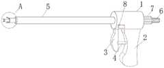
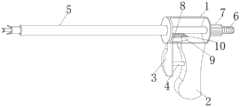
图1是本实用新型一种腔镜用尿道钳的整体结构示意图;Fig. 1 is the overall structure schematic diagram of a kind of laparoscopic urethral forceps of the present utility model;
图2是本实用新型一种腔镜用尿道钳的钳套内部结构示意图;Fig. 2 is a schematic diagram of the internal structure of a clamp cover of a urethral forceps for laparoscopic use of the utility model;
图3是本实用新型一种腔镜用尿道钳的左钳、右钳的放大结构示意图;Fig. 3 is a schematic diagram of the enlarged structure of the left clamp and the right clamp of a urethral forceps for laparoscopic use of the utility model;
附图中,各标号所代表的部件列表如下:In the accompanying drawings, the list of parts represented by each label is as follows:
1-钳套,2-钳柄,3-推柄,4-推柱,5-主套管,6-副套管,7-螺套,8-按钮,9-U形卡块,10-第一卡齿,11-套杆,12-撑开钳,13-夹持钳。1-Clamp sleeve, 2-Clamp handle, 3-Push handle, 4-Push column, 5-Main sleeve, 6-Auxiliary sleeve, 7-Screw sleeve, 8-Button, 9-U-shaped block, 10- The first locking tooth, 11-cover rod, 12-expanding pliers, 13-holding pliers.
具体实施方式Detailed ways
下面将结合本实用新型实施例中的附图,对本实用新型实施例中的技术方案进行清楚、完整地描述,显然,所描述的实施例仅仅是本实用新型一部分实施例,而不是全部的实施例。基于本实用新型中的实施例,本领域普通技术人员在没有作出创造性劳动前提下所获得的所有其它实施例,都属于本实用新型保护的范围。The technical solutions in the embodiments of the present invention will be clearly and completely described below in conjunction with the accompanying drawings in the embodiments of the present invention. Obviously, the described embodiments are only part of the embodiments of the present invention, not all of them. example. Based on the embodiments of the present utility model, all other embodiments obtained by persons of ordinary skill in the art without creative efforts belong to the scope of protection of the present utility model.
为了更加清晰的描述本实用新型的内容,下面结合具体实施例做以下描述:In order to describe the content of the present utility model more clearly, do following description below in conjunction with specific embodiment:
实施例Example
参阅图1-3所示,一种腔镜用尿道钳,包括钳套1、钳柄2、推柄3、主套管5、副套管6、套杆11、撑开钳12、夹持钳13;所述钳套1内部中空,钳套1的底部设有滑槽,钳套1的首端上转动设有与钳套1连通的螺套7;所述钳柄2与钳套1的底部连接,钳柄2上设有滑孔,滑孔内设有第一弹簧;所述推柄3的一端穿过滑槽位于钳套1内,推柄3上设有推柱4,推柱4滑动设置在滑孔内;所述主套管为两端开口的空心圆柱体,主套管的首端与钳套1的尾端连通;所述副套管为两端开口的空心圆柱体,副套管设置在主套管内,副套管的首端穿过钳套1内部与螺套7螺纹连接,副套管位于钳套1内部的底端上设有通槽;所述套杆11设置在副套管内;所述推柄3位于钳套1内的端头穿过通槽与套杆11连接;所述撑开钳12、夹持钳13均包括左钳、右钳,撑开钳12、夹持钳13上的左钳、右钳分别铰接在副套管6、套杆11的端头并在左钳、右钳与副套管6、套杆11之间分别设有扭簧。Referring to Fig. 1-3, a kind of urethral forceps for laparoscopic, comprises
所述滑槽与通槽的长度一致,通槽位于滑槽的正上方。The length of the chute is consistent with that of the through groove, and the through groove is located directly above the chute.
还包括固定机构;所述固定机构包括按钮8、U形卡块9、第二弹簧、第一卡齿10、第二卡齿;所述按钮8滑动设置在钳套1上,U形卡块9设置在钳套1内部,U形卡块9的一端与按钮8连接,U形卡块9将推柄3位于钳套1内部的端头包裹在内部,第二弹簧设置在按钮8对侧的钳套1内壁上,第一卡齿10倾斜设置在U形卡块9的内壁上,第二卡齿设置在推柄3位于U形卡块9内的外壁上,第一卡齿10与第二卡齿对应设置。It also includes a fixing mechanism; the fixing mechanism includes a
所述第一卡齿10的延长线朝向螺套7方向。The extension line of the
具体使用时,移动主套管至尿道处,转动螺套7在螺纹作用下将副套管推出撑开钳12,撑开钳12上的左钳、右钳在扭簧作用下朝相反的方向移动,在撑开钳12的带动下将尿道周围的组织遮挡、撑开,按压按钮8推动U形卡块9压缩第二弹簧,使得第一卡齿10与第二卡齿分离,并在第一弹簧的作用下推动推柄3远离钳柄2移动,推柄3带动套杆11移动,将夹持钳13推出副套管6,夹持钳13上的左钳、右钳在扭簧作用下展开,调整夹持钳13上的左钳、右钳位于尿道两侧,操作者手部握持推柄3,使得推柄3朝向钳柄2移动,将套杆11拉入副套管6内,夹持钳13上的左钳、右钳相向移动夹持尿道。During specific use, move the main sleeve to the urethra, turn the
在本说明书的描述中,参考术语“一个实施例”、“示例”、“具体示例”等的描述意指结合该实施例或示例描述的具体特征、结构、材料或者特点包含于本实用新型的至少一个实施例或示例中。在本说明书中,对上述术语的示意性表述不一定指的是相同的实施例或示例。而且,描述的具体特征、结构、材料或者特点可以在任何的一个或多个实施例或示例中以合适的方式结合。In the description of this specification, descriptions referring to the terms "one embodiment", "example", "specific example" and the like mean that the specific features, structures, materials or characteristics described in conjunction with the embodiment or example are included in the description of the present invention. In at least one embodiment or example. In this specification, schematic representations of the above terms do not necessarily refer to the same embodiment or example. Furthermore, the specific features, structures, materials or characteristics described may be combined in any suitable manner in any one or more embodiments or examples.
以上公开的本实用新型优选实施例只是用于帮助阐述本实用新型。优选实施例并没有详尽叙述所有的细节,也不限制该实用新型仅为所述的具体实施方式。显然,根据本说明书的内容,可作很多的修改和变化。本说明书选取并具体描述这些实施例,是为了更好地解释本实用新型的原理和实际应用,从而使所属技术领域技术人员能很好地理解和利用本实用新型。本实用新型仅受权利要求书及其全部范围和等效物的限制。The preferred embodiments of the present invention disclosed above are only used to help explain the present invention. The preferred embodiments do not exhaust all details, nor do they limit the utility model to the described specific implementations. Obviously, many modifications and variations can be made based on the contents of this specification. This specification selects and specifically describes these embodiments in order to better explain the principle and practical application of the utility model, so that those skilled in the art can well understand and utilize the utility model. The invention is to be limited only by the claims and their full scope and equivalents.
Claims (4)
Translated fromChinesePriority Applications (1)
| Application Number | Priority Date | Filing Date | Title |
|---|---|---|---|
| CN202220606025.6UCN219048726U (en) | 2022-03-18 | 2022-03-18 | Urethral forceps for endoscope |
Applications Claiming Priority (1)
| Application Number | Priority Date | Filing Date | Title |
|---|---|---|---|
| CN202220606025.6UCN219048726U (en) | 2022-03-18 | 2022-03-18 | Urethral forceps for endoscope |
Publications (1)
| Publication Number | Publication Date |
|---|---|
| CN219048726Utrue CN219048726U (en) | 2023-05-23 |
Family
ID=86348335
Family Applications (1)
| Application Number | Title | Priority Date | Filing Date |
|---|---|---|---|
| CN202220606025.6UExpired - Fee RelatedCN219048726U (en) | 2022-03-18 | 2022-03-18 | Urethral forceps for endoscope |
Country Status (1)
| Country | Link |
|---|---|
| CN (1) | CN219048726U (en) |
- 2022
- 2022-03-18CNCN202220606025.6Upatent/CN219048726U/ennot_activeExpired - Fee Related
Similar Documents
| Publication | Publication Date | Title |
|---|---|---|
| CN108095805B (en) | Abdominal minimally invasive surgery clamp | |
| CN105997182A (en) | Automatic elastic line tightening mechanism of self-tightening type elastic line loop ligature device | |
| CN201551378U (en) | Intercondylar spine fracture reduction forceps | |
| CN219048726U (en) | Urethral forceps for endoscope | |
| CN109199500B (en) | A nail pushing device for laparoscopic purse-string suturing device | |
| CN209122328U (en) | A threading clip for surgical suture | |
| CN109316215A (en) | A kind of celioscope gall-bladder operation pulling clamp | |
| CN216358578U (en) | Peritoneoscope electrocoagulation operation forceps head | |
| CN107550527A (en) | Multi-functional flap traction device in Breast Surgery art | |
| CN205988298U (en) | A kind of Hofman drag hook assists spreading forcepss | |
| CN111568541B (en) | A flexible minimally invasive surgical instrument based on natural orifice | |
| CN210962158U (en) | A blocking forceps for DVC minimally invasive surgery | |
| CN211883892U (en) | A claw-type mechanism for removing diseased tissue in vivo | |
| CN209048219U (en) | A kind of liftable skin incision dilator | |
| CN207693640U (en) | A kind of thoracoscope round rod type surgical clamp | |
| CN207286135U (en) | A kind of double end laparoscope grasping forceps | |
| CN221750674U (en) | Laparoscopic operating forceps | |
| CN207445024U (en) | Bone surgery wire fixer | |
| CN218739007U (en) | Biopsy forceps device with head capable of turning | |
| CN110840498A (en) | Intestinal canal tractor | |
| CN111227882A (en) | Claw type mechanism for taking out in-vivo diseased tissue | |
| CN221383668U (en) | A liver portal blocker | |
| CN211796679U (en) | Novel hemostatic forceps for obstetrics and gynecology department | |
| CN209360773U (en) | A kind of celioscope gall-bladder operation pulling clamp | |
| CN215227996U (en) | A thoracoscopic surgical instrument with dual purpose of passing a line and pushing a knot |
Legal Events
| Date | Code | Title | Description |
|---|---|---|---|
| GR01 | Patent grant | ||
| GR01 | Patent grant | ||
| CF01 | Termination of patent right due to non-payment of annual fee | Granted publication date:20230523 | |
| CF01 | Termination of patent right due to non-payment of annual fee |