CN219021327U - A blood vessel suturing device and a blood vessel suturing system - Google Patents
A blood vessel suturing device and a blood vessel suturing systemDownload PDFInfo
- Publication number
- CN219021327U CN219021327UCN202222625676.2UCN202222625676UCN219021327UCN 219021327 UCN219021327 UCN 219021327UCN 202222625676 UCN202222625676 UCN 202222625676UCN 219021327 UCN219021327 UCN 219021327U
- Authority
- CN
- China
- Prior art keywords
- feedback
- assembly
- blood vessel
- connecting sleeve
- needle
- Prior art date
- Legal status (The legal status is an assumption and is not a legal conclusion. Google has not performed a legal analysis and makes no representation as to the accuracy of the status listed.)
- Active
Links
Images


Landscapes
- Surgical Instruments (AREA)
Abstract
Translated fromChinese
Description
Translated fromChinese技术领域technical field
本实用新型涉及医疗器械技术领域,尤其涉及一种适用于心血管介入治疗术后的血管缝合器及血管缝合系统。The utility model relates to the technical field of medical devices, in particular to a blood vessel suturing device and a blood vessel suturing system suitable for cardiovascular interventional treatment.
背景技术Background technique
随着介入手术的大量应用,术后能否快速、有效止血成为了关系到手术成败的重要因素。由于术中抗凝及抗血小板药物的使用,传统上医生借助多种外部压力的办法来闭合动/静脉,包括直接加压、沙袋或机械夹协助等;近年来,越来越多医生在患者介入术后对其使用血管缝合器进行大中血管的缝合,以促进止血及伤口快速恢复;其中使用率最高的血管缝合器当属Abbott的Proglide血管缝合器,因其与切开缝合相比,有降低并发症几率、缩短患者制动及住院时间等优势,可广泛应用于冠脉介入、射频消融、结构性心脏病、体外循环等心脏领域相关术式。With the extensive application of interventional surgery, the ability to quickly and effectively stop bleeding after surgery has become an important factor related to the success of the operation. Due to the use of anticoagulant and antiplatelet drugs during surgery, doctors traditionally use various external pressure methods to close arteries/veins, including direct pressure, sandbags or mechanical clips; After the intervention, a vascular suturer is used to suture large and medium blood vessels to promote hemostasis and rapid wound recovery; the most widely used vascular suturer is Abbott's Proglide vascular suturer, because compared with incision and suturing, It has the advantages of reducing the risk of complications, shortening the immobilization and hospitalization time of patients, and can be widely used in coronary intervention, radiofrequency ablation, structural heart disease, extracorporeal circulation and other cardiac procedures.
ProGlide血管缝合器在使用过程中需要下压推柄,使前、后针头分别插入对应的套筒内,再抽拔推柄,从而带动轨线穿过渔夫结,进而实现缝合血管切口的目的。但是在下压推柄时,由于无法直视前、后针头与套筒的接触情况,如果继续进行缝合操作就有可能导致血管缝合失败。During the use of the ProGlide vascular suture device, the push handle needs to be pressed down so that the front and rear needles are inserted into the corresponding sleeves respectively, and then the push handle is pulled out to drive the trajectory through the fisherman's knot, thereby achieving the purpose of suturing the vascular incision. However, when the push handle is pressed down, because the contact situation between the front and rear needles and the sleeve cannot be directly seen, if the suture operation is continued, the blood vessel suture failure may be caused.
基于上述原因,如何设计一种带有连接反馈功能的血管缝合器,保证医生在下压针柄时即可直接判断前、后针是否完全插入到对应的套筒中,以提高血管缝合的成功率,便成了目前需要解决的问题。Based on the above reasons, how to design a vascular suture device with connection feedback function to ensure that the doctor can directly judge whether the front and rear needles are completely inserted into the corresponding sleeves when pressing the needle handle down, so as to improve the success rate of vascular suture , has become a problem that needs to be solved at present.
实用新型内容Utility model content
本实用新型公开了一种血管缝合器及血管缝合系统,旨在解决现有技术中存在的技术问题。The utility model discloses a blood vessel suturing device and a blood vessel suturing system, aiming at solving the technical problems existing in the prior art.
本实用新型采用下述技术方案:The utility model adopts the following technical solutions:
一方面,本申请公开了一种血管缝合器,包括:近端组件、线脚组件及推柄组件;On the one hand, the present application discloses a blood vessel stapler, including: a proximal assembly, a stitch assembly and a push handle assembly;
线脚组件可限位滑动地设置于近端组件的远端;线脚组件包括线脚主体,在线脚主体的两侧分别均设有连接套筒;The thread assembly can be slidably arranged at the far end of the proximal assembly; the thread assembly includes a thread body, and connecting sleeves are respectively provided on both sides of the thread body;
推柄组件的远端设有连接针,连接针能够与连接套筒卡接;The far end of the push handle assembly is provided with a connecting pin, which can be engaged with the connecting sleeve;
连接套筒的筒壁设有窗口与挡片,挡片由窗口的近端径向向内并向远端延伸,挡片的尺寸满足:在连接针穿入连接套筒内后,挡片能够至少部分嵌入窗口内,并封闭窗口;The cylinder wall of the connecting sleeve is provided with a window and a baffle, and the baffle extends radially inward from the proximal end of the window and extends to the far end. embedded at least partially within the window and enclosing the window;
线脚主体中设有第一反馈腔;第一反馈腔入口与窗口相连通,第一反馈腔出口开设于线脚主体的一侧壁;A first feedback chamber is provided in the main body of the molding; the entrance of the first feedback chamber is connected to the window, and the outlet of the first feedback chamber is opened on the side wall of the main body of the molding;
近端组件中设有第二反馈腔;第二反馈腔入口能够在线脚组件展开后与第一反馈腔出口同轴对接;第二反馈腔出口设置于近端组件的近端,并与外界连通。The proximal component is provided with a second feedback chamber; the inlet of the second feedback cavity can be coaxially connected with the outlet of the first feedback cavity after the wire foot assembly is deployed; the outlet of the second feedback cavity is set at the proximal end of the proximal component and communicates with the outside world .
作为优选的技术方案,第一反馈腔至少与一个连接套筒的窗口相连通。As a preferred technical solution, the first feedback cavity communicates with at least one window of the connecting sleeve.
作为优选的技术方案,第一反馈腔设有两个第一反馈腔入口,两个第一反馈腔入口分别与两个连接套筒的窗口相连通。As a preferred technical solution, the first feedback cavity is provided with two inlets of the first feedback cavity, and the two inlets of the first feedback cavity communicate with the windows of the two connecting sleeves respectively.
作为优选的技术方案,第一反馈腔沿线脚主体的长度方向设置;第一反馈腔入口设置于第一反馈腔的端部;两个第一反馈腔入口连通同一第一反馈腔出口。As a preferred technical solution, the first feedback chamber is arranged along the length direction of the molding body; the inlet of the first feedback chamber is arranged at the end of the first feedback chamber; the inlets of the two first feedback chambers are connected to the outlet of the same first feedback chamber.
作为优选的技术方案,连接针的远端包括凸台部和定位凹部;凸台部用于穿入连接套筒时挤压挡片,使得挡片嵌入并封闭窗口;定位凹部用于为挡片的部分复位提供容纳空间,并使得挡片卡挡住凸台部。As a preferred technical solution, the distal end of the connecting needle includes a boss portion and a positioning recess; the boss portion is used to squeeze the baffle when passing through the connecting sleeve, so that the baffle embeds and closes the window; the positioning recess is used for the baffle Part of the reset provides accommodating space, and makes the blocking piece block the boss part.
作为优选的技术方案,定位凹部的最小直径被配置为:允许挡片至少部分复位、至少部分封闭窗口。As a preferred technical solution, the minimum diameter of the positioning recess is configured to: allow at least a partial reset of the blocking piece and at least partially close the window.
作为优选的技术方案,定位凹部的最大直径不小于连接套筒的内径,使得连接针与连接套筒卡接后,二者过渡连接或过盈连接。As a preferred technical solution, the maximum diameter of the positioning recess is not smaller than the inner diameter of the connecting sleeve, so that after the connecting needle and the connecting sleeve are clamped, the two are connected in a transition or interference connection.
作为优选的技术方案,第二反馈腔沿近端组件的轴向设置;第二反馈腔入口被配置为:能够与线脚组件展开后的第一反馈腔出口同轴连通,并密封对接。As a preferred technical solution, the second feedback chamber is arranged along the axial direction of the proximal assembly; the inlet of the second feedback chamber is configured to communicate coaxially with the outlet of the first feedback chamber after the wire foot assembly is deployed, and to be butted in a sealed manner.
作为优选的技术方案,还包括缝合器主体;近端组件的近端沿轴向穿设于缝合器主体中;第二反馈腔出口连接有一根反馈管,反馈管近端由缝合器主体中穿出。As a preferred technical solution, it also includes a stapler main body; the proximal end of the proximal assembly is axially threaded in the stapler main body; a feedback tube is connected to the outlet of the second feedback cavity, and the proximal end of the feedback tube is passed through the stapler main body. out.
作为优选的技术方案,还包括远端组件;As a preferred technical solution, it also includes a remote component;
推柄组件的近端沿轴向穿设于缝合器主体中,推柄组件的远端穿设于近端组件中;线脚组件设置于近端组件与远端组件之间。The proximal end of the push handle assembly is threaded through the main body of the stapler along the axial direction, and the distal end of the push handle assembly is threaded in the proximal assembly; the stitch assembly is arranged between the proximal assembly and the distal assembly.
作为优选的技术方案,连接针包括前针及后针;连接套筒包括前针连接套筒及后针连接套筒;前针连接套筒及后针连接套筒的远端通过连接线相互连接。As a preferred technical solution, the connecting needle includes a front needle and a rear needle; the connecting sleeve includes a front needle connecting sleeve and a rear needle connecting sleeve; the distal ends of the front needle connecting sleeve and the rear needle connecting sleeve are connected to each other by a connecting wire .
作为优选的技术方案,前针的远端设有缝线结及轴线,后针的远端设有轨线。As a preferred technical solution, the distal end of the front needle is provided with a suture knot and an axis, and the distal end of the rear needle is provided with a trajectory.
另一方面,本申请还包括一种血管缝合系统,包括如上任一项所述的血管缝合器,还包括缝线调整器。On the other hand, the present application also includes a blood vessel suturing system, which includes the blood vessel suturing device described in any one of the above items, and also includes a suture adjuster.
本实用新型与现有技术相比的优点在于:Compared with the prior art, the utility model has the following advantages:
本实用新型在缝合器的线脚组件中设有第一反馈腔,第一反馈腔的两个入口分别和前针连接套筒、后针连接套筒中的窗口相连通,第一反馈腔的两个入口共用一个出口;窗口内侧设有挡片,在前、后针分别穿入连接套筒中后能够分别将窗口封闭;在血管缝合器的近端组件中设有第二反馈腔,第二反馈腔入口能够在线脚组件完全展开后和第一反馈腔出口同轴连通,并密封对接,第二反馈腔出口连接有反馈管,反馈管的近端开放于缝合器主体外。The utility model is provided with a first feedback chamber in the stitch assembly of the suturing device, and the two inlets of the first feedback chamber communicate with the windows in the front needle connecting sleeve and the rear needle connecting sleeve respectively, and the two inlets of the first feedback chamber communicate with each other respectively. The two inlets share one outlet; the inner side of the window is provided with a baffle, which can respectively seal the window after the front and rear needles penetrate into the connecting sleeve; a second feedback chamber is arranged in the proximal assembly of the blood vessel stapler, and the second The inlet of the feedback cavity can be coaxially connected with the outlet of the first feedback cavity after the wire foot assembly is fully deployed, and is sealed and docked. The outlet of the second feedback cavity is connected with a feedback tube, and the proximal end of the feedback tube is opened outside the main body of the stapler.
本实用新型中的血管缝合器在使用时,当线脚组件在血管内展开,血管中的血流会依次流经连接套筒、第一反馈腔及第二反馈腔,并最终由反馈管的近端开口呈搏动性流出;当下压推柄组件,前针及后针正确穿入相对应的连接套筒内后,连接套筒内的挡片受到挤压会封闭窗口,此时反馈管停止搏动性出血,证明前、后针与各自对应的连接套筒正确卡接;由于第一反馈腔的两个入口共用一个出口,因此,若有某一连接针未正确穿入连接套筒中,反馈管都不会停止向外流血,此时需要调整或更换血管缝合器。When the blood vessel suturing device in the utility model is in use, when the thread foot assembly is deployed in the blood vessel, the blood flow in the blood vessel will flow through the connecting sleeve, the first feedback chamber and the second feedback chamber in turn, and finally the blood flow will be passed by the proximal feedback tube. The end opening is pulsating and flows out; when the push handle assembly is pressed down, the front needle and the rear needle are correctly inserted into the corresponding connecting sleeve, and the baffle in the connecting sleeve is squeezed to close the window, and the feedback tube stops pulsating at this time Proof that the front and rear needles are correctly clamped with their respective connecting sleeves; since the two inlets of the first feedback chamber share one outlet, if a certain connecting needle is not correctly inserted into the connecting sleeve, the feedback If the tube does not stop bleeding outwards, the vessel stapler needs to be adjusted or replaced.
通过本实用新型,使得医师在下压推柄组件时即可判断前针和后针是否都插入到对应的连接套筒内,从而提高血管缝合的成功率。Through the utility model, the doctor can judge whether the front needle and the rear needle are inserted into the corresponding connecting sleeve when pressing down the push handle assembly, thereby improving the success rate of blood vessel suturing.
附图说明Description of drawings
为了更清楚地说明本实用新型实施例的技术方案,下面将对实施例描述中所需要使用的附图作简单地介绍,构成本实用新型的一部分,本实用新型的示意性实施例及其说明解释本实用新型,并不构成对本实用新型的不当限定。在附图中:In order to more clearly illustrate the technical solutions of the embodiments of the present invention, the accompanying drawings that need to be used in the description of the embodiments will be briefly introduced below, which constitute a part of the present invention, the schematic embodiments of the present invention and their descriptions Explanation of the utility model does not constitute an improper limitation of the utility model. In the attached picture:
图1为本实用新型实施例1公开的一种优选实施方式中血管缝合器的立体图;Fig. 1 is a perspective view of a blood vessel suturing device in a preferred embodiment disclosed in Example 1 of the present invention;
图2为本实用新型实施例1公开的一种优选实施方式中血管缝合器的局部分解结构示意图;Fig. 2 is a schematic diagram of a partial exploded structure of a blood vessel suturing device in a preferred embodiment disclosed in Example 1 of the present invention;
图3为图2中A处的局部放大图;Fig. 3 is a partial enlarged view of place A in Fig. 2;
图4为本实用新型实施例1公开的一种优选实施方式中线脚组件的结构示意图;Fig. 4 is a schematic structural view of the molding assembly in a preferred embodiment disclosed in Example 1 of the present invention;
图5为本实用新型实施例1公开的一种优选实施方式中线脚主体的结构示意图;Fig. 5 is a schematic structural view of the molding main body in a preferred embodiment disclosed in Example 1 of the present utility model;
图6为本实用新型实施例1公开的一种优选实施方式中线脚主体的剖视图;Fig. 6 is a cross-sectional view of the molding body in a preferred embodiment disclosed in Example 1 of the present utility model;
图7为本实用新型实施例1公开的一种优选实施方式中线脚主体的另一剖视图;Fig. 7 is another cross-sectional view of the molding body in a preferred embodiment disclosed in Example 1 of the present utility model;
图8为本实用新型实施例1公开的一种优选实施方式中近端组件的结构示意图;Fig. 8 is a schematic structural view of the proximal assembly in a preferred embodiment disclosed in Example 1 of the present invention;
图9为图8中B处的局部放大图;Fig. 9 is a partial enlarged view of place B in Fig. 8;
图10a为本实用新型实施例1中连接针未穿入连接套筒时的结构示意图;Fig. 10a is a schematic structural view of the connection needle in Example 1 of the present invention when it does not penetrate the connection sleeve;
图10b为本实用新型实施例1中连接针刚穿入连接套筒时的结构示意图;Fig. 10b is a schematic diagram of the structure when the connecting needle has just penetrated into the connecting sleeve in Embodiment 1 of the present utility model;
图10c为本实用新型实施例1中连接针完全穿入连接套筒时的结构示意图。Fig. 10c is a schematic diagram of the structure when the connecting needle completely penetrates into the connecting sleeve in Embodiment 1 of the present utility model.
附图标记说明:Explanation of reference signs:
缝合器主体10,扳手11,快速剪刀口12,标记管13;推柄组件20,连接针21,凸台部211,定位凹部212,前针22,后针23;线脚组件30,连接套筒31,前针连接套筒311,后针连接套筒312,挡片32,窗口33,连接线34,线脚主体35,通孔351,卡口36;反馈管40;近端组件50;远端组件60;第一反馈腔70,第一反馈腔入口71,第一反馈腔出口72;第二反馈腔80,第二反馈腔入口81。Stapler
具体实施方式Detailed ways
为使本实用新型的目的、技术方案和优点更加清楚,下面将结合本实用新型具体实施例及相应的附图对本实用新型技术方案进行清楚、完整地描述。在本实用新型的描述中,需要说明的是,术语“或”通常是以包括“和/或”的含义而进行使用的,除非内容另外明确指出外。In order to make the purpose, technical solution and advantages of the utility model clearer, the technical solution of the utility model will be clearly and completely described below in conjunction with specific embodiments of the utility model and corresponding drawings. In the description of the present utility model, it should be noted that the term "or" is usually used in the sense of including "and/or", unless the content clearly states otherwise.
显然,所描述的实施例仅是本实用新型一部分实施例,而不是全部的实施例。基于本实用新型中的实施例,本领域普通技术人员在没有做出创造性劳动前提下所获得的所有其他实施例,都属于本实用新型保护的范围。Apparently, the described embodiments are only some of the embodiments of the present invention, but not all of them. Based on the embodiments of the present utility model, all other embodiments obtained by persons of ordinary skill in the art without making creative efforts belong to the scope of protection of the present utility model.
在下述实施例中。“近端”是指接近操作者的一端,“远端”是指远离操作者的一端。In the following examples. "Proximal end" refers to the end close to the operator, and "distal end" refers to the end away from the operator.
为解决现有技术中存在的问题,本申请实施例提供了一种血管缝合器,包括:近端组件50、线脚组件30及推柄组件20;线脚组件30可限位滑动地设置于近端组件50的远端;线脚组件30包括线脚主体35,在线脚主体35的两侧分别均设有连接套筒31;推柄组件20的远端设有连接针21,连接针21能够与连接套筒31卡接;连接套筒31的筒壁设有窗口33与挡片32,挡片32由窗口33的近端径向向内并向远端延伸,挡片32的尺寸满足:在连接针21穿入连接套筒31内后,挡片32能够至少部分嵌入窗口33内,并封闭窗口33;线脚主体35中设有第一反馈腔70;第一反馈腔入口71与窗口33相连通,第一反馈腔出口72开设于线脚主体35的一侧壁;近端组件50中设有第二反馈腔80;第二反馈腔入口81能够在线脚组件30展开后与第一反馈腔出口72同轴对接;第二反馈腔80出口设置于近端组件50的近端,并与外界连通。In order to solve the problems existing in the prior art, the embodiment of the present application provides a blood vessel stapler, including: a
实施例1Example 1
目前在心血管介入治疗术后的血管缝合领域,临床常使用Proglide血管缝合器,但是在按压其推柄组件时,并不能确定推柄组件的连接针是否准确穿入连接套筒并与之卡接,无论两个连接针都未与各自对应的连接套筒正确卡接,还是仅一个连接针未与其连接套筒正确卡接,都会使得缝线无法互相配合,从而无法实现血管上伤口缝合的目的,最终造成血管缝合的失败导致预后不良。At present, in the field of blood vessel suturing after cardiovascular interventional therapy, Proglide blood vessel suturing device is often used clinically, but when pressing its push handle assembly, it is not sure whether the connecting needle of the push handle assembly is accurately inserted into the connecting sleeve and engaged with it , whether the two connecting needles are not correctly engaged with their respective connecting sleeves, or only one connecting needle is not correctly engaged with its connecting sleeve, the sutures will not be able to cooperate with each other, so that the purpose of suturing the wound on the blood vessel cannot be achieved , eventually resulting in failure of vascular suture leading to poor prognosis.
基于上述原因,本实施例提供了一种具有连接反馈功能的血管缝合器,以实现在下压针柄组件的过程中即能判断前针、后针是否完全插入到对应的套筒中,从而实现血管缝合的成功率。Based on the above reasons, this embodiment provides a blood vessel suturing device with a connection feedback function, so that it can be judged whether the front needle and the rear needle are completely inserted into the corresponding sleeve during the process of pressing down the needle handle assembly, so as to realize Success rate of vessel suturing.
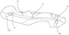
参考图1,在一种优选实施方式中,血管缝合器包括缝合器主体10、近端组件50、远端组件60、线脚组件30及推柄组件20。Referring to FIG. 1 , in a preferred embodiment, a blood vessel stapler includes a stapler
优选地,缝合器主体10与近端组件50、远端组件60依次连接,推柄组件20的近端沿轴向穿设于缝合器主体10中,推柄组件20的远端穿设于近端组件50中,线脚组件30设置于近端组件50与远端组件60之间。Preferably, the stapler
优选地,缝合器主体10上设有扳手11,该扳手11通过一联动件与线脚组件30连接,联动件设置于近端组件50中;当抬起扳手11,即可控制线脚组件30进行一定角度的旋转,并相对于近端组件50的轴线呈展开状态;本领域技术人员应理解,本实施例中的缝合器主体10的结构与Proglide血管缝合器的主体结构一致,缝合器主体10与线脚组件30之间的联动及结构配合关系与现有技术中的结构一致,在此不再赘述。Preferably, a wrench 11 is provided on the
参考图2-4,优选地,在线脚组件30的两端均设有连接套筒31,分别为前针连接套筒311及后针连接套筒312,连接套筒31的远端通过同一连接线34相连;在初始状态下,线脚组件30的长轴方向与近端组件50的长轴方向保持一致,当抬起扳手11时,线脚组件30能够顺时针旋转一定角度,使得前针连接套筒311及后针连接套筒312的开口方向均朝向近端。With reference to Fig. 2-4, preferably, the two ends of
本领域技术人员应理解,线脚组件30两端的前针连接套筒311及后针连接套筒312并非平行设置,而是存在一定角度,具体角度的设置应与推柄组件20远端的连接针21的角度相匹配,如图3。Those skilled in the art should understand that the front
优选地,推柄组件20内设有两根支杆,两针支杆的远端设有连接针21,分别为前针22和后针23;在初始状态下,前针22和后针23顺应于近端组件50的延伸方向,且置于近端组件50内,当按下推柄组件20,前针22及后针23向远端延伸,二者呈一定角度张开,分别卡接于前针连接套筒311及后针连接套筒312。Preferably, the
优选地,前针22及一根支杆穿设于一条缝线(轴线)的缝线结中,后针23与另一支杆并列设置,且后针23与另一缝线(轨线)固定;当按下推柄组件20,前针22卡接于前针连接套筒311,后针23卡接于后针连接套筒312,当从缝合器主体10中拔出推柄组件20时,前针22及前针连接套筒311带动连接线34、连接线34带动后针连接套筒312及轨线,使得轨线能够穿入到轴线的线结中,以完成血管缝合的初始操作。Preferably, the
本领域技术人员应理解,上述血管缝合器的操作方式及各个结构的配合方式与Proglide血管缝合器相同,在此不再赘述。Those skilled in the art should understand that the operation mode of the above-mentioned blood vessel stapler and the cooperation mode of each structure are the same as those of the Proglide blood vessel stapler, and will not be repeated here.
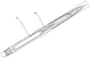
参考图4、图5,优选地,线脚组件30包括线脚主体35,线脚主体35呈大致扁柄状;在线脚组件30的两端分别开设有两个通孔351,通孔351的尺寸与连接套筒31的尺寸相匹配,使得二者能够过渡配合。With reference to Fig. 4, Fig. 5, preferably,
优选地,连接套筒31一端开放,一端封闭,连接针21能够穿入连接套筒31中,并使得二者卡接;优选地,每个连接套筒31的侧壁均设有一个窗口33,在窗口33的近端设有挡片32,挡片32由窗口33的近端向径向向内并向远端延伸;优选地,在连接针21未穿入连接套筒31之前,挡片32与连接套筒31的筒壁呈现一夹角,如图10a。Preferably, one end of the connecting
可选地,挡片32由形状记忆金属或偏压设置的回弹材料制作;优选地,挡片32的尺寸与窗口33的尺寸可精密配合,使得当连接针21穿入连接套筒31中时,挡片32受到连接针21的径向挤压而向外弯折,并最终完全嵌入连接套筒31中,此时挡片32和连接套筒31的筒壁处于同一曲面,以便于连接针21通过,如图10b;而后挡片32能够部分复位,以抵压连接针21远端,防止其脱离连接套筒31,实现连接套筒31与连接针21之间的卡接连接,如图10c。Optionally, the
在一种优选实施方式中,为增强结构的一体性及结构强度,挡片32选用与连接套筒31相同的材料进行制作,或对连接套筒31进行冲压、激光切割或弯折等工艺以形成挡片32结构。本领域技术人员应理解,为使挡片32实现其弯曲并复位的功能,亦可选择使用其他加工工艺。In a preferred embodiment, in order to enhance the integrity and structural strength of the structure, the blocking
在一种优选实施方式中,当挡片32受到连接针21挤压而弯折到与连接套筒31筒壁处于同一曲面时,挡片32的内侧弯曲弧度应与筒壁的弧度相匹配,以保证筒壁内形成一光滑的通道,便于连接针21穿过。In a preferred embodiment, when the
在一种优选实施方式中,挡片32的尺寸满足:在连接针21穿入连接套筒31内并与之卡接后,挡片32能够至少部分嵌入窗口33内,并封闭窗口33。In a preferred embodiment, the size of the blocking
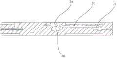
如图5-图7,优选地,在线脚主体35中设有第一反馈腔70,第一反馈腔70为开设于线脚主体35中一条两端贯通的腔道;第一反馈腔入口71与至少一个连接套筒31中的窗口33相连通,第一反馈腔70的出口开设于线脚主体35的一侧壁。As shown in Fig. 5-Fig. 7, preferably, a
优选地,第一反馈腔入口71的尺寸与窗口33尺寸相配合,使得二者能够相对密封地相连通。Preferably, the size of the
优选地,在近端组件50中沿轴向设有第二反馈腔80,第二反馈腔80为开设于近端组件50中的一条两端贯通的腔道;优选地,第二反馈腔入口81能够在线脚组件30展开后与第一反馈腔出口72同轴对接;第二反馈腔80出口设置于近端组件50的近端,并与外界连通。Preferably, a
如图8-图9,近端组件50由管状件、联动件、支杆等组成,在一种优选实施方式中,可在近端组件50的管状件内壁设置一腔道,也即第二反馈腔80。As shown in Figures 8-9, the
优选地,第二反馈腔入口81被配置为:能够与线脚组件30展开后的第一反馈腔出口72同轴连通,并密封对接。在一种优选实施方式中,第二反馈腔入口81与第一反馈腔出口72尺寸相同,且第二反馈腔入口81的位置与线脚组件30展开后第一反馈腔出口72的位置相匹配。Preferably, the
在一种优选实施方式中,第二反馈腔80出口还连接有一根反馈管40,反馈管40与第二反馈腔80出口同轴固接,反馈管40的近端由缝合器主体10中穿出。In a preferred embodiment, the outlet of the
优选的,反馈管40可使用与医用导管相同的材料制作,以避免与血管连通后污染血液造成感染。Preferably, the
当线脚组件30在目标血管中展开后,血管中的血液能够流入连接套筒31中,然后穿越连接套筒31的窗口33,依次流经第一反馈腔70、第二反馈腔80及反馈管40,并最终由反馈管40的近端呈搏动性流出。当下压推柄组件20,连接针21穿入连接套筒31中,连接针21挤压连接套筒31内的挡片32,使其封堵住窗口33,此时反馈管40近端的搏动性出血消失;若搏动性出血未消失,则证明连接针21并未正确与连接套筒31卡接。When the
在一种优选实施方式中,由于连接针21中可能只有前针22或可能只有后针23不容易与连接套筒31正确卡接,因此第一反馈腔70的入口仅对应设置一个,并与不容易卡接的前针连接套筒311或后针连接套筒312中的窗口33相连通。In a preferred embodiment, since there may be only the
如图6、图7,在另一优选实施方式中,第一反馈腔70设有两个入口,两个第一反馈腔入口71分别与前针连接套筒311中的窗口33和后针连接套筒312中的窗口33相连通,以保证无论哪一连接针21未与连接套筒31正确卡接,操作医生均能得到实时反馈。As shown in Fig. 6 and Fig. 7, in another preferred embodiment, the
优选地,第一反馈腔70沿线脚主体35的长度方向设置;两个第一反馈腔入口71分别设置于第一反馈腔70的端部;两个第一反馈腔入口71连通同一个第一反馈腔出口72。Preferably, the
优选地,线脚主体35的中心位置设有卡口36,该卡口36用于与联动件连接;第一反馈腔70在线脚主体35中设置时需绕避该卡口36,以防止血管中的血液无法经过第一反馈腔70向外流出。在一种优选实施方式中,第一反馈腔出口72大致设置于线脚主体35的一侧壁的中心位置,并保证在线脚组件30完全展开后能够与第二反馈腔入口81同轴对接并密封连通。Preferably, a
在一种优选实施方式中,第一反馈腔入口71及第一反馈腔出口72均呈开口向外的大致喇叭状,以利于血液的流入及流出;更优选地,第二反馈腔入口81及第二反馈腔80出口亦设置为开口向外的大致喇叭状;更优选地,反馈管40的远端部及近端部均设置为开口向外的喇叭状,以保证用于反馈提示的血液能够从反馈管40流畅地流出。In a preferred embodiment, the
在一种优选实施方式中,在第一反馈腔70、第二反馈腔80及反馈管40内壁还设有抗凝涂层,避免因血液暴露后形成血栓而导致管腔堵塞、无法正确进行操作反馈等问题的出现。In a preferred embodiment, an anticoagulant coating is provided on the inner wall of the
优选地,连接针21的远端包括凸台部211和定位凹部212,其中,凸台部211可以在连接针21穿入连接套筒31内时挤压挡片32,使得挡片32嵌入并封闭窗口33,此时反馈管40近端停止搏动性出血,便于医师判断此时连接针21与连接套管已经正确卡接;定位凹部212能够为挡片32的部分复位提供容纳空间,使得挡片32卡挡住凸台部211的近端,防止连接针21从连接套筒31内脱出。Preferably, the distal end of the
在一种优选实施方式中,定位凹部212呈大致的锥形,且定位凹部212的外轮廓与挡片32适配,保证凸台部211穿越挡片32后,挡片32能够在定位凹部212进行部分复位,保证挡片32能够抵住凸台部211的近端。In a preferred embodiment, the positioning
优选地,定位凹部212的最大直径不小于连接套筒31的内径,更优选地,定位凹部212与连接针21的近端平滑过渡,因此,连接针21的近端直径亦不小于连接套筒31的直径,以保证连接针21与连接套筒31在卡接后对连接套筒31的近端入口进行封堵,避免在挡片32没有对窗口33完全封闭的情况下,血管中的血液继续进入连接套筒31中,并依次经第一反馈腔70、第二反馈腔80及反馈管40向外流出,造成错误的反馈信息,影响缝合操作。Preferably, the maximum diameter of the
优选地,定位凹部212的最小直径被配置为:允许挡片32至少部分复位、至少部分封闭窗口33。其中,挡片32的部分复位是为了卡挡住凸台部211的近端,防止连接针21与连接套筒31彼此脱离;挡片32至少部分封闭窗口33是为了保证在连接针21穿入连接套筒31中后,挡片32所截断的血流不再畅通,以证明连接针21与连接套筒31的正确卡接,而当定位凹部212的最小直径能够保证挡片32可以至少部分封闭窗口33时,即使连接针21在连接套筒31内轴向移动,仍能够保证第一反馈腔入口71的封闭状态,使得血液不再流向第一反馈腔70。Preferably, the smallest diameter of the
在本实施例中,医生在使用血管缝合器进行血管缝合时,远端组件60和线脚组件30依次进入血管中,抬起缝合器主体10上的扳手11,以使得线脚组件30在血管内完全展开,此时血管中的血流会依次流经连接套筒31、第一反馈腔70及第二反馈腔80,并最终由反馈管40的近端开口呈搏动性流出;当下压推柄组件20,前针22及后针23正确穿入相对应的连接套筒31内后,连接套筒31内的挡片32受到挤压会封闭窗口33,此时反馈管40停止搏动性出血,证明前、后针23与各自对应的连接套筒31正确卡接;由于第一反馈腔70的两个入口共用一个出口,因此,若有某一连接针21未正确穿入连接套筒31中,反馈管40都不会停止向外流血,此时需要调整或更换血管缝合器。In this embodiment, when a doctor uses a blood vessel stapler to suture a blood vessel, the
实施例2Example 2
本实施例提供了一种血管缝合系统,包血管缝合器和缝线调整器,已经包括于实施例1中的各个特征在本实施例得到自然继承。This embodiment provides a blood vessel suturing system, a vessel-encapsulating suturing device and a suture adjuster, and the various features included in Embodiment 1 are naturally inherited in this embodiment.
优选地,本实施例中的缝线调整器与Proglide血管缝合器系统当中的缝线调整器结构相同,且其结构为现有技术,在此实施例中不再详述其具体结构。Preferably, the suture adjuster in this embodiment has the same structure as the suture adjuster in the Proglide vascular stapler system, and its structure is the prior art, and its specific structure will not be described in detail in this embodiment.
优选地,血管缝合器的缝合器主体10上还设有一个快速剪刀口12,用于切断缝线。Preferably, the stapler
在本实施例中,血管缝合系统的使用方法如下:In this embodiment, the use method of the vascular suturing system is as follows:
以股动脉的缝合为例,首先从导引鞘内行股动脉造影确定穿刺点在股总动脉上,防止缝线打到血管后壁及可能造成的血管前后壁的缝闭,透视评估股总动脉的直径、钙化、扭曲,以及动脉壁是否有夹层或其他血管疾病,经导管鞘置入导丝,撤出鞘时按压腹股沟处止血,然后沿导丝置入血管缝合器,直到导丝快速交换口靠近皮肤表面,在导丝快速交换口进入体内前移除导丝,继续推送器械进去,直到标记管13处看到持续的搏动性血流流出,停止推进器械。Taking the suturing of the femoral artery as an example, first perform femoral angiography from inside the introducer sheath to confirm that the puncture point is on the common femoral artery, to prevent the suture from hitting the posterior wall of the vessel and possibly causing suturing of the anterior and posterior walls of the vessel, and evaluate the common femoral artery through perspective Diameter, calcification, distortion, and whether the artery wall has dissection or other vascular diseases, insert the guide wire through the catheter sheath, press the groin to stop bleeding when the sheath is withdrawn, and then place a vascular stapler along the guide wire until the guide wire is quickly exchanged The mouth is close to the surface of the skin, remove the guide wire before the quick exchange port of the guide wire enters the body, continue to push the instrument in until a continuous pulsatile blood flow is seen at the
将血管缝合器保持在45°角,抬起缝合器主体10上的扳手11,打开线脚组件30,此时反馈管40的近端开口出现搏动性出血;轻轻回撤器械,使线脚组件30抵住动脉壁,如果线脚组件30的位置正确,标记管13的回血将停止或明显减少。Keep the blood vessel stapler at an angle of 45°, lift the wrench 11 on the
稳定并保持住器械,按下推柄组件20,直到推柄组件20与缝合器主体10的近端紧密接触,在直视下确认推柄组件20与器械紧密接触后,若同时反馈管40停止搏动性出血,证明前、后针23与各自对应的连接套筒31正确卡接,可以进行下一步操作;若反馈管40近端仍有流血,证明有某一连接针21未正确穿入连接套筒31中,否则需要调整推柄组件20或更换血管缝合器。Stabilize and hold the instrument, press the
将推柄组件20和缝线完全从缝合器主体10中拔出,直到缝线收紧,使用快速剪刀口12剪断缝线,放松器械,然后将扳手11推回至原始位置,收回线脚组件30,回撤器械,直到导丝快速标记口露出皮肤,从近端部分同时拉紧两根缝线,将缝线末端从近端组件50中拿出。Pull out the
将一根缝线缠绕在左手食指上,沿肌肉同轴方向轻轻拉动,另一根缝线放在左手拇指和食指之间,打开缝线调整器上的操作手柄,将两根缝线40同时置于缝线调整器远端的缝线窗,松开操作手柄置入缝线,向前推结,缝线调整器送到位置后,轻拉两根缝线中的轴线锁紧线结,从穿刺通道内撤出缝线调整器,通过让病人咳嗽或曲腿来测试止血效果。Wrap one suture around the index finger of the left hand and gently pull it along the coaxial direction of the muscle. At the same time, place the suture window at the far end of the suture adjuster, release the operating handle to insert the suture, push the knot forward, and after the suture adjuster is sent to the position, lightly pull the axis of the two sutures to lock the knot , withdraw the suture adjuster from the puncture channel, and test for hemostasis by having the patient cough or bend the leg.
一旦确认止血,使用缝线调整器上的剪刀剪断缝线,在保持缝线张力的情况下,将两根缝线都置入缝线调整器并一直顶到动脉表面,向后拉动扳手11,剪断缝线,并保持扳手11关闭状态撤出缝线,完成血管的缝合。Once the hemostasis is confirmed, use the scissors on the suture adjuster to cut the sutures, and while maintaining the suture tension, put both sutures into the suture adjuster and press them all the way to the surface of the artery, pull the wrench 11 backwards, Cut the suture, and keep the closed state of the wrench 11 to withdraw the suture, and complete the suturing of the blood vessel.
本领域技术人员应理解,缝线调整器的操作方法与其自身结构相匹配,其结构及操作方法均已经是公开技术,因此不再一一赘述其结构之间的配合关系。Those skilled in the art should understand that the operation method of the suture adjuster matches its own structure, and its structure and operation method are already public technologies, so the cooperation relationship between the structures will not be repeated one by one.
上面结合附图对本实用新型的实施例进行了描述,但是本实用新型并不局限于上述的具体实施方式,上述的具体实施方式仅仅是示意性的,而不是限制性的,本领域的普通技术人员在本实用新型的启示下,在不脱离本实用新型宗旨和权利要求所保护的范围情况下,还可做出很多形式,均属于本实用新型的保护之内。Embodiments of the present utility model have been described above in conjunction with the accompanying drawings, but the present utility model is not limited to the above-mentioned specific implementation, and the above-mentioned specific implementation is only illustrative, rather than restrictive. Under the enlightenment of the utility model, personnel can also make many forms without departing from the purpose of the utility model and the scope protected by the claims, all of which belong to the protection of the utility model.
Claims (13)
Translated fromChinesePriority Applications (1)
| Application Number | Priority Date | Filing Date | Title |
|---|---|---|---|
| CN202222625676.2UCN219021327U (en) | 2022-09-30 | 2022-09-30 | A blood vessel suturing device and a blood vessel suturing system |
Applications Claiming Priority (1)
| Application Number | Priority Date | Filing Date | Title |
|---|---|---|---|
| CN202222625676.2UCN219021327U (en) | 2022-09-30 | 2022-09-30 | A blood vessel suturing device and a blood vessel suturing system |
Publications (1)
| Publication Number | Publication Date |
|---|---|
| CN219021327Utrue CN219021327U (en) | 2023-05-16 |
Family
ID=86313256
Family Applications (1)
| Application Number | Title | Priority Date | Filing Date |
|---|---|---|---|
| CN202222625676.2UActiveCN219021327U (en) | 2022-09-30 | 2022-09-30 | A blood vessel suturing device and a blood vessel suturing system |
Country Status (1)
| Country | Link |
|---|---|
| CN (1) | CN219021327U (en) |
- 2022
- 2022-09-30CNCN202222625676.2Upatent/CN219021327U/enactiveActive
Similar Documents
| Publication | Publication Date | Title |
|---|---|---|
| US7063710B2 (en) | Intracardiac suture device | |
| CN100435742C (en) | Endocardial suture device | |
| CN100466989C (en) | Liquid-tight puncture and occlusion device for anatomical structures | |
| US20100161040A1 (en) | Cardiovascular valve and valve housing apparatuses and systems | |
| CN114082075B (en) | An auxiliary bending control sheath | |
| JPH09108228A (en) | Catherter assembly for heart cavity suture operation | |
| JP2008500125A (en) | Suture device | |
| JP3733580B2 (en) | Closure collection tool for defect closure | |
| WO2017066986A1 (en) | Multi-clip ligation device | |
| CN117357188B (en) | Tissue ligation system and use method thereof | |
| CN219000400U (en) | Vascular stitching instrument | |
| JP4088978B2 (en) | Intracardiac suture device | |
| US20240009438A1 (en) | Devices and methods for fistula-free hemodialysis | |
| CN116211367A (en) | A blood vessel suturing device and a blood vessel suturing system | |
| CN219021327U (en) | A blood vessel suturing device and a blood vessel suturing system | |
| CN111134762A (en) | Disposable repeatedly openable soft tissue clamp | |
| US20090018555A1 (en) | System and method for attaching a vein, an artery, or a tube in a vascular environment | |
| CA3081942A1 (en) | Cannula for percutaneous minimally invasive cannulation of the vena cava | |
| CN113081131B (en) | Auxiliary system for transapical surgery | |
| JP3859257B2 (en) | Suture cutting device for intracardiac suture surgery | |
| CN222983090U (en) | Novel aortic proximal anastomosis system for coronary bypass | |
| CN219700139U (en) | Endoscopic blood clot removal device | |
| CN221903909U (en) | A retinal membrane peeling device | |
| WO1999023955A1 (en) | Vascular shunt apparatus | |
| CN116077112A (en) | Vascular closure, vascular closure system and method for operating vascular closure system |
Legal Events
| Date | Code | Title | Description |
|---|---|---|---|
| GR01 | Patent grant | ||
| GR01 | Patent grant | ||
| TR01 | Transfer of patent right | Effective date of registration:20250526 Address after:314400, No. 1 Honghu Road, Xishi Street, Haining City, Jiaxing City, Zhejiang Province, E Building, Juanhu Science and Technology City Life Health Innovation Park, 1st and 4th floors Patentee after:Zhejiang Newpulse Medical Technology Co.,Ltd. Country or region after:China Address before:611100 Floor 1-3, Building 4, No. 1919, Shuangyan Road, Chengdu Cross Strait Science and Technology Industry Development Park, Wenjiang District, Chengdu, Sichuan Patentee before:Chengdu newmai Biotechnology Co.,Ltd. Country or region before:China | |
| TR01 | Transfer of patent right |