CN219021092U - Handle and endoscope - Google Patents
Handle and endoscopeDownload PDFInfo
- Publication number
- CN219021092U CN219021092UCN202222799836.5UCN202222799836UCN219021092UCN 219021092 UCN219021092 UCN 219021092UCN 202222799836 UCN202222799836 UCN 202222799836UCN 219021092 UCN219021092 UCN 219021092U
- Authority
- CN
- China
- Prior art keywords
- handle
- piece
- locking
- traction wheel
- accommodating space
- Prior art date
- Legal status (The legal status is an assumption and is not a legal conclusion. Google has not performed a legal analysis and makes no representation as to the accuracy of the status listed.)
- Active
Links
Images


Landscapes
- Endoscopes (AREA)
Abstract
Description
Translated fromChinese技术领域technical field
本申请涉及医疗器械技术领域,尤其涉及一种手柄及内窥镜。The present application relates to the technical field of medical instruments, in particular to a handle and an endoscope.
背景技术Background technique
内窥镜能够经由人体的天然腔道或微创孔洞进入人体,能够直接对人体内的目标部位进行检查、诊断乃至微创手术,因此内窥镜在现代医学中得到了越来越广泛的应用。Endoscopes can enter the human body through the natural cavity or minimally invasive holes of the human body, and can directly perform inspection, diagnosis and even minimally invasive surgery on target parts in the human body. Therefore, endoscopes have been more and more widely used in modern medicine. .
在相关技术中,内窥镜包括手柄和插入部,操作者通过拨动手柄上的拨杆、并经由牵引机构实现对插入部的主动弯曲段的姿态控制,从而调节前端摄像头的朝向。但是,相关技术的内窥镜需要操作者维持手动固定拨杆的状态,才能确保摄像头始终朝向目标部位,可见,上述内窥镜存在操作繁琐的不足。In the related art, the endoscope includes a handle and an insertion part. The operator can adjust the orientation of the front camera by turning the lever on the handle and controlling the posture of the active bending section of the insertion part through the traction mechanism. However, the endoscope of the related art requires the operator to maintain the state of manually fixing the lever to ensure that the camera is always facing the target site. It can be seen that the above-mentioned endoscope has the disadvantage of cumbersome operation.
实用新型内容Utility model content
本申请提供一种手柄及内窥镜,能够简化内窥镜的操作。The present application provides a handle and an endoscope, which can simplify the operation of the endoscope.
为了解决上述问题,本申请采用下述技术方案:In order to solve the above problems, the application adopts the following technical solutions:
第一方面,本申请实施例提供一种手柄,应用于内窥镜,所述手柄包括拨动件、锁止件、套管、牵引轮和弹性件,其中:In the first aspect, the embodiment of the present application provides a handle, which is applied to an endoscope, and the handle includes a toggle member, a locking member, a sleeve, a traction wheel and an elastic member, wherein:
所述牵引轮开设有第一容置空间,所述拨动件沿其轴向可移动地设于所述第一容置空间内;The traction wheel is provided with a first accommodating space, and the toggle member is movably arranged in the first accommodating space along its axial direction;
所述锁止件与所述拨动件固定连接,且自所述牵引轮的端面一侧延伸至所述套管内,所述弹性件与所述拨动件相连,用以向所述拨动件施加预紧力,以使所述锁止件随所述拨动件移动至与所述套管抵接的位置。The locking piece is fixedly connected with the toggle piece, and extends from the side of the end face of the traction wheel into the casing, and the elastic piece is connected with the toggle piece for pushing towards the toggle piece. The member exerts a pretightening force, so that the locking member moves to a position abutting against the sleeve along with the toggle member.
第二方面,本申请实施例提供一种内窥镜,包括插入部以及本申请实施例第一方面所述的手柄,所述手柄与所述插入部相连。In a second aspect, an embodiment of the present application provides an endoscope, including an insertion part and the handle according to the first aspect of the embodiment of the present application, and the handle is connected to the insertion part.
本申请实施例采用的技术方案能够达到以下有益效果:The technical solution adopted in the embodiment of the present application can achieve the following beneficial effects:
在本申请实施例公开手柄及内窥镜中,通过在牵引轮的侧面设置与拨动件固接且延伸至套管内的锁止件,配置拨动件沿其轴向可移动地设于牵引轮内,并由弹性件向拨动件施加预紧力,使锁止件能够随拨动件移动至与套管抵接的位置,由于锁止件与套管之间存在摩擦作用,二者可实现相互制动,从而使拨动件和牵引轮均处于锁止状态。In the handle and the endoscope disclosed in the embodiment of the present application, by setting a locking piece on the side of the traction wheel that is fixedly connected to the toggle piece and extends into the casing, the toggle piece is arranged to be movably arranged on the traction wheel along its axial direction. inside the wheel, and the elastic part applies a pre-tightening force to the toggle, so that the locking part can move with the toggle to the position where it abuts against the bushing. Due to the friction between the locking part and the bushing, the two Mutual braking can be achieved so that both the toggle and traction wheels are locked.
相较于相关技术,本申请实施例公开的手柄中,牵引轮能够实现自锁,操作者无需手动维持固定拨动件,显然有效地简化了内窥镜的操作,优化了操作体验。Compared with related technologies, in the handle disclosed in the embodiment of the present application, the traction wheel can realize self-locking, and the operator does not need to manually maintain the fixed toggle, which obviously effectively simplifies the operation of the endoscope and optimizes the operating experience.
附图说明Description of drawings
此处所说明的附图用来提供对本申请的进一步理解,构成本申请的一部分,本申请的示意性实施例及其说明用于解释本申请,并不构成对本申请的不当限定。The drawings described here are used to provide a further understanding of the application and constitute a part of the application. The schematic embodiments and descriptions of the application are used to explain the application and do not constitute an improper limitation to the application.
在附图中:In the attached picture:
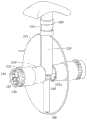
图1为本申请一些实施例公开的内窥镜的结构示意图;FIG. 1 is a schematic structural view of an endoscope disclosed in some embodiments of the present application;
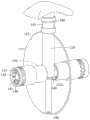
图2为本申请一些实施例公开的内窥镜隐藏部分壳体的结构示意图;Fig. 2 is a schematic structural view of the hidden part of the housing of the endoscope disclosed in some embodiments of the present application;
图3为图2中A处的局部放大图;Fig. 3 is a partial enlarged view of place A in Fig. 2;
图4为本申请一些实施例公开的手柄中部分结构的分解示意图;Fig. 4 is an exploded schematic view of some structures in the handle disclosed in some embodiments of the present application;
图5为本申请一些实施例公开的锁止件与套管相互制动时的结构示意图;Fig. 5 is a structural schematic diagram of the mutual braking of the locking member and the bushing disclosed in some embodiments of the present application;
图6为本申请一些实施例公开的锁止件与套管分离时的结构示意图。Fig. 6 is a schematic structural view of the locking member disclosed in some embodiments of the present application when it is separated from the sleeve.
附图标记说明:Explanation of reference signs:
100-手柄、100-handle,
110-壳体、111-容置腔、112-第一避让口、120-拨动件、130-锁止件、131-卡接凸起、131a-引导面、140-套管、141-卡接凹陷、150-牵引轮、151-轮本体、151a-第一容置空间、151b-第二避让口、152-转轴、152a-第二容置空间、152b-第三避让口、153-护套管部、160-弹性件、170-轴瓦、180-环箍、190-牵引绳、110-housing, 111-accommodating cavity, 112-the first avoidance port, 120-toggle piece, 130-locking piece, 131-clamping protrusion, 131a-guiding surface, 140-sleeve, 141-card Connecting depression, 150-traction wheel, 151-wheel body, 151a-first accommodation space, 151b-second escape opening, 152-rotating shaft, 152a-second accommodation space, 152b-third escape opening, 153-guard Casing part, 160-elastic part, 170-bearing bush, 180-ring hoop, 190-traction rope,
200-插入部、200-insert part,
300-转接线缆。300-transfer cable.
具体实施方式Detailed ways
为使本申请的目的、技术方案和优点更加清楚,下面将结合本申请具体实施例及相应的附图对本申请技术方案进行清楚、完整地描述。显然,所描述的实施例仅是本申请一部分实施例,而不是全部的实施例。基于本申请中的实施例,本领域普通技术人员在没有做出创造性劳动前提下所获得的所有其他实施例,都属于本申请保护的范围。In order to make the purpose, technical solution and advantages of the present application clearer, the technical solution of the present application will be clearly and completely described below in conjunction with specific embodiments of the present application and corresponding drawings. Apparently, the described embodiments are only some of the embodiments of the present application, rather than all the embodiments. Based on the embodiments in this application, all other embodiments obtained by persons of ordinary skill in the art without making creative efforts belong to the scope of protection of this application.
以下结合附图,详细说明本申请各个实施例公开的技术方案。The technical solutions disclosed in various embodiments of the present application will be described in detail below with reference to the accompanying drawings.
针对相关技术的内窥镜在使用过程中需要操作者手动维持固定拨杆而导致的操作繁琐的技术问题,本申请实施例提供了一种手柄,应用于内窥镜。Aiming at the technical problem of cumbersome operation caused by requiring the operator to manually maintain and fix the lever during use of the endoscope in the related art, the embodiment of the present application provides a handle, which is applied to the endoscope.
请参见图1~图6,本申请实施例公开的手柄100包括拨动件120、锁止件130、套管140、牵引轮150和弹性件160。Referring to FIGS. 1 to 6 , the
手柄100包括壳体110,壳体110为手柄100的基础构件,其作为其他构件的安装基础,并能够为设于其内部容置腔111的构件提供防护作用。在本申请的实施例中,套管140、牵引轮150等均设于容置腔111内。The
牵引轮150可转动地设于容置腔111内,牵引绳190套设于牵引轮150上,在牵引轮150转动时牵引绳190随动而对其远端的主动弯曲段进行牵拉,从而实现了内窥镜的插入部200的弯曲动作。在本申请的实施例中,牵引轮150开设有第一容置空间151a,拨动件120设于第一容置空间151a内,相当于拨动件120嵌设在牵引轮150内部,通过控制拨动件120即可带动牵引轮150转动;当然,拨动件120需延伸至壳体110外部,从而便于操作者对拨动件120进行操控,壳体110上可开设有第一避让口112,用以供拨动件120穿设。The
其中,本申请的实施例对牵引绳190的数量不做限制,其可以为一条、两条(如图2~图4所示)、四条等。Wherein, the embodiment of the present application does not limit the number of
在本申请的实施例中,拨动件120沿其轴向可移动地设于第一容置空间151a内,也就是说,拨动件120能够在第一容置空间151a内与牵引轮150产生相对移动,且移动方向位于拨动件120自身的轴向上,该结构特征具体表征为,操作者可按压拨动件120而使拨动件120在牵引轮150内部沿轴向移动。其中,拨动件120可以为拨杆、把手等结构形式。In the embodiment of the present application, the
与此同时,锁止件130与拨动件120固定连接,且自牵引轮150的端面一侧延伸至套管140内,弹性件160与拨动件120相连,用以向拨动件120施加预紧力,以使锁止件130随拨动件120移动至与套管140抵接的位置。At the same time, the
可以理解,锁止件130和拨动件120基于二者的固接关系,拨动件120在移动时会带动锁止件130移动。其中,弹性件160基于其自身的弹性特性,其在储能状态下会向拨动件120施加预紧力,拨动件120在预紧力的作用会被驱动或存在移动趋势,以使拨动件120能够沿与操作者的按压方向的相反方向移动。It can be understood that, based on the fixed relationship between the
锁止件130沿牵引轮150的端面一侧延伸至套管140内,而锁止件130随拨动件120沿拨动件120的轴向移动,套管140的侧壁位于锁止件130的移动路径上,因此,在弹性件160的预紧力的驱动作用下,锁止件130会随拨动件120移动至与套管140抵接的位置。The
如图5所示,在锁止件130与套管140的侧壁抵接的情况下,在弹性件160施加的预紧力作用下,锁止件130与套管140的侧壁之间会存在较大的摩擦作用,二者之间实现了相互制动,也即锁止件130无法相对于套管140产生相对运动,从而使拨动件120和牵引轮150均被固定,而处于锁止状态。As shown in FIG. 5 , when the
如图6所示,在需要对主动弯曲段进行弯曲控制时,操作者可通过按压拨动件120而使拨动件120沿轴向移动而带动锁止件130移动,直至锁止件130与套管140分离,二者之间不存在能够阻止相对运动的摩擦阻力,操作者即可通过驱动拨动件120而带动牵引轮150转动,从而经由牵引绳190实现对主动弯曲段的弯曲控制。As shown in Figure 6, when it is necessary to control the bending of the active bending section, the operator can press the
可见,本申请实施例公开的手柄100在具体使用时,通过对拨动件120的按压操作,即可实现牵引轮150在锁止状态和解锁状态间的切换,而且在将主动弯曲段调节至预设弯曲状态时,解除对拨动件120的按压即可实现牵引轮150的自锁,操作者无需手动维持固定拨动件120,显然有效地简化了内窥镜的操作,优化了操作体验。It can be seen that, when the
其中,锁止件130自牵引轮150的端面一侧延伸出,其利用了牵引轮150端面侧的空间,有利于提升手柄100内部的空间利用率,且不会增大手柄100自身的尺寸。Wherein, the locking
套管140设于容置腔111内,其可以与壳体110一体成型,也可成型为单独的构件、并固定设于容置腔111中。The
本申请实施例未限制弹性件160与拨动件120的具体驱动关系,弹性件160可向拨动件120施加作为预紧力的推力,则需要将弹性件160布置为压缩状态时推动拨动件120与套管140相抵接的连接关系;弹性件160可向拨动件120施加作为预紧力的拉力,则需要将弹性件160布置为拉伸状态时牵拉拨动件120与套管140相抵接的连接关系。The embodiment of the present application does not limit the specific driving relationship between the
如图4~图6所示,本申请实施例的套管140和锁止件130均可设为两组,两组锁止件130和套管140分别设于牵引轮150不同的端面一侧,如此即可在牵引轮150的相对两侧实现自锁效果,由此能够进一步地强化手柄100中关于牵引轮150的自锁性能。As shown in Figures 4 to 6, the
如图3~图6所示,在本申请的一些实施例中,在套管140的侧壁与锁止件130的周侧壁中,其中一者设有卡接凸起131,另一者设有卡接凹陷141,在锁止件130与套管140抵接的情况下,卡接凸起131与卡接凹陷141卡接配合。As shown in Figures 3 to 6, in some embodiments of the present application, one of the side walls of the
可以理解,卡接凹陷141为卡接凸起131提供了容置空间,二者卡接配合时卡接凸起131相当于嵌设在卡接凹陷141内部,二者间不仅能够通过摩擦阻力相互制动,还能够通过相互限位而实现制动,该实施例通过卡接配合的方式可进一步地强化锁止件130与套管140件的制动效果,从而进一步地优化牵引轮150的自锁性能。It can be understood that the
其中,如图4所示,卡接凸起131设于锁止件130上,卡接凹陷141设于套管140上,当然,卡接凸起131也可设于套管140上,而卡接凹陷141相应设于锁止件130上。本申请实施例对卡接凸起131和卡接凹陷141的具体结构形式也未进行限制,举例来说,卡接凸起131可以为凸点、凸块、凸条等,卡接凹陷141可以为卡槽、卡接孔等。Wherein, as shown in FIG. 4 , the engaging
如图4所示,在本申请的一些实施例中,卡接凸起131的侧面设有引导面131a,引导面131a用于引导卡接凸起131滑入卡接凹陷141。可以理解,由于为了确保卡接凸起131和卡接凹陷141在配合时的稳定性,二者的尺寸通常设置得较为接近,这样就使得在装配时难以快速实现对准卡装。对此,本实施例中的卡接凸起131通过设置引导面131a,通过引导面131a引导卡接凸起131滑入到卡接凹陷141中,从而使得卡接凸起131快速地与卡接凹陷141实现组配,以确保手柄100在使用中锁止件130能够顺利与套管140卡接而实现牵引轮150的自锁功能。As shown in FIG. 4 , in some embodiments of the present application, a
其中,引导面131a可以为导向斜面(如图4所示)、导向弧面等类型。Wherein, the guiding
如图4~图6所示,在本申请的一些实施例中,弹性件160设于第一容置空间151a内,弹性件160的两端分别与拨动件120和牵引轮150相连,并用于向拨动件120施加预紧推力。As shown in Figures 4 to 6, in some embodiments of the present application, the
在此种结构布局下,弹性件160设于牵引轮150内,其相当于复用了牵引轮150内部的空间,相较于将弹性件160设于容置腔111的方案而无需占据手柄100内部的布局空间,由此能够提升优化手柄100内部的结构布局,并提升结构紧凑性。其中,弹性件160的两端分别与拨动件120和牵引轮150的内壁相连,由于其是通过压缩储能而施加预紧推力,其可以与拨动件120和牵引轮150的内壁之间为固接关系,也可以为抵接关系。Under such a structural layout, the
同时,由于弹性件160设于第一容置空间151a内,第一容置空间151a的内壁可对弹性件160起到约束引导作用,其能够防止弹性件160发生偏斜、扭转等情况,从而确保了弹性件160沿预设方向对拨动件120施加预紧推力。At the same time, since the
如图3~图6所示,在本申请的一些实施例中,牵引轮150包括轮本体151以及设于轮本体151的端面的转轴152,轮本体151开设有第一容置空间151a,转轴152与套管140转动配合;转轴152具有沿轴向开设的第二容置空间152a,锁止件130经由第二容置空间152a延伸至套管140内。As shown in Figures 3 to 6, in some embodiments of the present application, the
具体而言,在此种结构布局下,锁止件130位于转轴152中,其复用了转轴152的内部空间,相较于将锁止件130设于容置腔111的方案而无需占据手柄100内的布局空间,这样能够优化手柄100内部的结构布局,并提升结构紧凑性。同时,此种结构布局下的套管140不仅作为轴承结构为转轴152提供了支撑基础,其具备与锁止件130相互制动的作用,可见,该实施例中的套管140也具备一物多用的功能,这样能够对手柄100内部的结构布局起到一定的优化作用,还能够降低生产成本。Specifically, under this structural layout, the locking
当然,锁止件130可以自轮本体151的端面穿设出而设置在转轴152之外的区域,如此情况下,牵引轮150可在端面开设第二避让口151b,用以供锁止件130通过,为了配合拨动件120的移动,第二避让口151b根据拨动件120的移动路径延伸布置。Certainly, the locking
如图3~图6所示,在本申请的一些实施例中,牵引轮150包括开设于其端面的第二避让口151b以及开设于转轴152的第三避让口152b,第二避让口151b与第一容置空间151a连通,第三避让口152b与第二容置空间152a连通,第二避让口151b和第三避让口152b用于供锁止件130通过。As shown in Figures 3 to 6, in some embodiments of the present application, the
可以理解,由于锁止件130与拨动件120固定连接,因此二者可同时进行装配,而锁止件130需要装配至转轴152的第二容置空间152a中,其在随拨动件120装配的过程中,会与轮本体151的侧壁和转轴152的侧壁产生干涉。对此,基于该实施例的结构布局,在对拨动件120与锁止件130进行安装时,可直接将拨动件120对准第一容置空间151a进行插入,而锁止件130可通过第二避让口151b和第三避让口152b顺利通过而不会与轮本体151的侧壁和转轴152的侧壁产生干涉,从而将锁止件130顺利地装配至转轴152内。It can be understood that since the locking
其中,锁止件130和拨动件120可以一体成型,它们能够通过上述实施例实现快捷装配。当然,锁止件130和拨动件120也可以分别为独立的构件,锁止件130可以在拨动件120在第一容置空间151a中安装到位后再与拨动件120连接,例如,如图4所示,在牵引轮150包括转轴152以及转轴152具有第二容置空间152a的实施例中,锁止件130可以经由第二容置空间152a的开口伸入转轴152内并与拨动件120的侧面连接,具体可通过卡接、螺纹连接等方式实现连接,同时,该实施例中,牵引轮150的端面以及转轴152的侧壁不需要开设第二避让口151b和第三避让口152b,这样可提升牵引轮150整体的结构强度。Wherein, the locking
如图3~图6所示,在本申请的一些实施例中,手柄100还包括轴瓦170,轴瓦170设于套管140与转轴152之间,且轴瓦170套设于转轴152。如此布局下,轴瓦170可在套管140与转轴152之间提供支撑作用,避免套管140和转轴152出现直接磨损,从而延长使用寿命。As shown in FIGS. 3-6 , in some embodiments of the present application, the
其中,轴瓦170可开设有油槽,通过输出润滑油而形成油膜,以进一步地优化套管140和转轴152在相对转动时的顺畅度。Wherein, the bearing
在本申请的转轴152具有第三避让口152b的实施例中,轴瓦170可对应第三避让口152b设置,如此,轴瓦170不仅能够在套管140与转轴152之间起到支撑作用,且还能够与锁止件130限位配合,从而防止锁止件130从转轴152中脱离。In the embodiment of the present application where the
进一步地,轴瓦170可以为轴套,轴套可沿整个周向套设在转轴152上,其与转轴152的组配可靠性更优。Further, the bearing
如图3~图6所示,在本申请的一些实施例中,牵引轮150还包括与轮本体151连接的护套管部153,护套管部153与第一容置空间151a连通,手柄100包括壳体110,护套管部153延伸至壳体110外,第二避让口151b延伸至护套管部153的开口处。As shown in Figures 3 to 6, in some embodiments of the present application, the
可以理解,拨动件120需要自牵引轮150处延伸至壳体110外部,以供操作者进行操控,而操作者常操控拨动件120的自由端,即远离牵引轮150的一端,如此情况下,拨动件120的受力点与其和轮本体151抵接的区域(位于第一容置空间151a的开口处)的距离较大,从而存在较大的力矩,这样会导致拨动件120与牵引轮150相互间挤压受损的问题。对此,该实施例基于护套管部153的设置,护套管部153可对拨动件120自第一容置空间151a延伸至壳体110外的部分进行包覆,如此可增大拨动件120与牵引轮150的接触面积,从而减弱相互的压强,降低了二者间出现挤压破坏的风险;同时,相较于轮本体151在第一容置空间151a的开口处的部分,护套管部153的顶端与拨动件120的自由端的间距更小,这样形成的力矩较小,也能够进一步地降低拨动件120与牵引轮150相互间挤压受损的风险。It can be understood that the driving
如图3~图6所示,在本申请的一些实施例中,手柄100还包括环箍180,环箍180套设于护套管部153。可以理解,环箍180可对护套管部153进行束紧,在操控拨动件120的情况下,拨动件120会与护套管部153产生相对挤压,环箍180能够防止护套管部153被挤压变形,对护套管部153起到保护作用。同时,正是由于环箍180对护套管部153的束紧作用,其能够确保护套管部153与拨动件120紧密贴合,避免二者间出现晃动磕碰。As shown in FIGS. 3 to 6 , in some embodiments of the present application, the
如图3所示,环箍180可以设为多个,其中包括与轮本体151邻近设置的环箍180,以及靠近护套管部153的开口设置的环箍180,如此能够优化对护套管部153的束紧效果。As shown in FIG. 3 ,
如图1~图6所示,本申请实施例还提供一种内窥镜,其包括插入部200以及前述任一方案所提及的手柄100,如此就使该内窥镜具备了前述任一方案的有益效果,在此不再赘述。其中,手柄100与插入部200相连,操作者握持手柄100,并通过手柄100对插入部200的主动弯曲段实施控制。As shown in Figures 1 to 6, the embodiment of the present application also provides an endoscope, which includes an
如图1和图2所示,内窥镜还包括转接线缆300,其与手柄100相连,并用于连接外部显示器。As shown in FIG. 1 and FIG. 2 , the endoscope also includes an
本申请实施例所提及的内窥镜可以为置管镜、胃镜、肠镜、喉镜、纤维支气管镜等,本申请的实施例对内窥镜的种类不做具体限制。The endoscopes mentioned in the embodiments of the present application may be tubescopes, gastroscopes, colonoscopes, laryngoscopes, fiberoptic bronchoscopes, etc., and the embodiments of the present application do not specifically limit the types of endoscopes.
本申请上文实施例中重点描述的是各个实施例之间的不同,各个实施例之间不同的优化特征只要不矛盾,均可以组合形成更优的实施例,考虑到行文简洁,在此则不再赘述。The above-mentioned embodiments of this application focus on the differences between the various embodiments. As long as the different optimization features of the various embodiments are not contradictory, they can be combined to form a better embodiment. Considering the simplicity of the text, here No longer.
以上所述仅为本申请的实施例而已,并不用于限制本申请。对于本领域技术人员来说,本申请可以有各种更改和变化。凡在本申请的精神和原理之内所作的任何修改、等同替换、改进等,均应包含在本申请的权利要求范围之内。The above descriptions are only examples of the present application, and are not intended to limit the present application. For those skilled in the art, various modifications and changes may occur in this application. Any modification, equivalent replacement, improvement, etc. made within the spirit and principle of the present application shall be included within the scope of the claims of the present application.
Claims (10)
Priority Applications (1)
| Application Number | Priority Date | Filing Date | Title |
|---|---|---|---|
| CN202222799836.5UCN219021092U (en) | 2022-10-24 | 2022-10-24 | Handle and endoscope |
Applications Claiming Priority (1)
| Application Number | Priority Date | Filing Date | Title |
|---|---|---|---|
| CN202222799836.5UCN219021092U (en) | 2022-10-24 | 2022-10-24 | Handle and endoscope |
Publications (1)
| Publication Number | Publication Date |
|---|---|
| CN219021092Utrue CN219021092U (en) | 2023-05-16 |
Family
ID=86290799
Family Applications (1)
| Application Number | Title | Priority Date | Filing Date |
|---|---|---|---|
| CN202222799836.5UActiveCN219021092U (en) | 2022-10-24 | 2022-10-24 | Handle and endoscope |
Country Status (1)
| Country | Link |
|---|---|
| CN (1) | CN219021092U (en) |
Cited By (1)
| Publication number | Priority date | Publication date | Assignee | Title |
|---|---|---|---|---|
| CN119157462A (en)* | 2024-11-21 | 2024-12-20 | 湖南省华芯医疗器械有限公司 | A driving assembly, a handle and an endoscope |
- 2022
- 2022-10-24CNCN202222799836.5Upatent/CN219021092U/enactiveActive
Cited By (2)
| Publication number | Priority date | Publication date | Assignee | Title |
|---|---|---|---|---|
| CN119157462A (en)* | 2024-11-21 | 2024-12-20 | 湖南省华芯医疗器械有限公司 | A driving assembly, a handle and an endoscope |
| CN119157462B (en)* | 2024-11-21 | 2025-04-04 | 湖南省华芯医疗器械有限公司 | A driving assembly, a handle and an endoscope |
Similar Documents
| Publication | Publication Date | Title |
|---|---|---|
| CN219021092U (en) | Handle and endoscope | |
| CN115227183B (en) | Traction wheel, traction rope adjustment mechanism, operating handle and endoscope | |
| CN114795069B (en) | Disposable section of endoscope handle, endoscope handle and endoscope | |
| CN114795068B (en) | Disposable section of endoscope handle, endoscope handle and endoscope | |
| US20110077461A1 (en) | Endoscope and instrument lifting operation device for the same | |
| CN219048381U (en) | Traction rope assembly, traction mechanism, insertion part and endoscope | |
| US20220296078A1 (en) | Insertion-instrument bending operation mechanism and insertion instrument | |
| CN117297512A (en) | Haulage rope mounting structure, endoscope handle and endoscope | |
| CN218899389U (en) | Tensioning element, tensioning mechanism, handle and endoscope of an endoscope | |
| JP2024531704A (en) | Disposable portion of endoscope handle, endoscope handle and endoscope | |
| CN217938169U (en) | Endoscope and operating handle thereof | |
| CN119073875A (en) | A driving structure of a traction rope, an operating handle and an endoscope | |
| CN116058771A (en) | Handle shell, handle and endoscope | |
| WO2023216711A1 (en) | Disposable section and reusable section of endoscope handle and endoscope | |
| CN218572163U (en) | Reusable segments, operating handles and endoscopes | |
| CN218792197U (en) | Handle casing, handle and endoscope | |
| CN219323400U (en) | A traction rope reset mechanism, endoscope handle and endoscope | |
| CN116138710A (en) | Front end module, insertion portion, and endoscope | |
| ITMI972673A1 (en) | DEVICE FOR CONNECTING ELECTRICAL CONTACTS | |
| CN116115159A (en) | Handle and endoscope | |
| CN218899388U (en) | Rotating part for endoscope and endoscope | |
| CN218792198U (en) | Pull rope driving assembly of endoscope, disposable section, handle and endoscope | |
| CN218960674U (en) | Traction mechanism, handle and endoscope | |
| CN118319504B (en) | Transfer frame, trolley and endoscope system | |
| CN219021095U (en) | Endoscope and its handle |
Legal Events
| Date | Code | Title | Description |
|---|---|---|---|
| GR01 | Patent grant | ||
| GR01 | Patent grant |