CN218974891U - Electronic stylus and electronic equipment - Google Patents
Electronic stylus and electronic equipmentDownload PDFInfo
- Publication number
- CN218974891U CN218974891UCN202223060029.8UCN202223060029UCN218974891UCN 218974891 UCN218974891 UCN 218974891UCN 202223060029 UCN202223060029 UCN 202223060029UCN 218974891 UCN218974891 UCN 218974891U
- Authority
- CN
- China
- Prior art keywords
- pen
- section
- bracket
- force
- electronic
- Prior art date
- Legal status (The legal status is an assumption and is not a legal conclusion. Google has not performed a legal analysis and makes no representation as to the accuracy of the status listed.)
- Active
Links
Images


Classifications
- G—PHYSICS
- G06—COMPUTING OR CALCULATING; COUNTING
- G06F—ELECTRIC DIGITAL DATA PROCESSING
- G06F3/00—Input arrangements for transferring data to be processed into a form capable of being handled by the computer; Output arrangements for transferring data from processing unit to output unit, e.g. interface arrangements
- G06F3/01—Input arrangements or combined input and output arrangements for interaction between user and computer
- G06F3/03—Arrangements for converting the position or the displacement of a member into a coded form
- G06F3/033—Pointing devices displaced or positioned by the user, e.g. mice, trackballs, pens or joysticks; Accessories therefor
- G06F3/0354—Pointing devices displaced or positioned by the user, e.g. mice, trackballs, pens or joysticks; Accessories therefor with detection of 2D relative movements between the device, or an operating part thereof, and a plane or surface, e.g. 2D mice, trackballs, pens or pucks
- G06F3/03545—Pens or stylus
- G—PHYSICS
- G06—COMPUTING OR CALCULATING; COUNTING
- G06F—ELECTRIC DIGITAL DATA PROCESSING
- G06F3/00—Input arrangements for transferring data to be processed into a form capable of being handled by the computer; Output arrangements for transferring data from processing unit to output unit, e.g. interface arrangements
- G06F3/01—Input arrangements or combined input and output arrangements for interaction between user and computer
- G06F3/03—Arrangements for converting the position or the displacement of a member into a coded form
- G06F3/033—Pointing devices displaced or positioned by the user, e.g. mice, trackballs, pens or joysticks; Accessories therefor
- G06F3/0354—Pointing devices displaced or positioned by the user, e.g. mice, trackballs, pens or joysticks; Accessories therefor with detection of 2D relative movements between the device, or an operating part thereof, and a plane or surface, e.g. 2D mice, trackballs, pens or pucks
Landscapes
- Engineering & Computer Science (AREA)
- General Engineering & Computer Science (AREA)
- Theoretical Computer Science (AREA)
- Human Computer Interaction (AREA)
- Physics & Mathematics (AREA)
- General Physics & Mathematics (AREA)
- Position Input By Displaying (AREA)
Abstract
Description
Translated fromChinese技术领域Technical Field
本实用新型涉及触控技术领域,特别涉及一种电子触控笔及电子设备。The utility model relates to the field of touch control technology, in particular to an electronic touch pen and an electronic device.
背景技术Background Art
电子触控笔是一种小笔形的工具,用来输入指令到电脑屏幕、移动设备、绘图板等具有触摸屏的设备,用户可以通过触控笔点击触控屏幕来选取文件或绘画。为实现电子触控笔良好的书写性能,电子触控笔的各电极结构件之间的距离、电极之间的信号屏蔽以及电极的尺寸大小都有比较严格的要求。An electronic stylus is a small pen-shaped tool used to input commands to a computer screen, mobile device, drawing tablet or other device with a touch screen. Users can select files or draw by clicking the touch screen with the stylus. To achieve good writing performance of the electronic stylus, there are relatively strict requirements on the distance between the electrode structures of the electronic stylus, the signal shielding between the electrodes, and the size of the electrodes.
在相关技术中,现有电子触控笔通常在内部设置受力传递结构与笔芯连接感应笔芯的受力程度以在显示屏划出粗细不同的笔迹,然而现有的受力传递结构整体多为平行四边形框架结构,为确保灵敏度及稳定性四边形框架结构尺寸不能做的太小,占用内部空间过大,从而造成内部空间浪费,内部空间利用率不高。In the related art, existing electronic stylus pens are usually internally provided with a force transmission structure connected to the pen core to sense the force degree of the pen core so as to draw handwriting of different thicknesses on the display screen. However, the existing force transmission structure is mostly a parallelogram frame structure as a whole. In order to ensure sensitivity and stability, the size of the quadrilateral frame structure cannot be made too small, and the internal space is too large, thereby causing waste of internal space and low utilization of the internal space.
实用新型内容Utility Model Content
本实用新型的主要目的是提出一种电子触控笔及电子设备,旨在解决受力传递结构占用电子触控笔内部空间大的问题。The main purpose of the utility model is to provide an electronic touch pen and an electronic device, aiming to solve the problem that the force transmission structure occupies a large internal space of the electronic touch pen.
为实现上述目的,本实用新型提出的电子触控笔,包括:To achieve the above-mentioned purpose, the electronic touch pen proposed by the utility model comprises:
笔壳,所述笔壳具有用于与触控屏接触时使所述触控屏产生电信号的笔芯;A pen case, wherein the pen case has a pen core for causing the touch screen to generate an electrical signal when the pen case contacts the touch screen;
受力传递结构,设于所述笔壳内,所述受力传递结构包括应变片和笔芯支架,所述笔芯支架与所述笔芯连接;A force transmission structure is arranged in the pen housing, the force transmission structure comprises a strain gauge and a refill bracket, and the refill bracket is connected to the refill;
所述应变片包括固定段以及分别与所述固定段两端连接且弯折延伸出的受力段和检测段,所述笔芯支架贯穿所述受力段,且与所述受力段和所述检测段连接,所述检测段上设置有应变计;The strain gauge includes a fixed section, and a force-bearing section and a detection section respectively connected to both ends of the fixed section and extending out of the bending section, the refill bracket passes through the force-bearing section, and is connected to the force-bearing section and the detection section, and a strain gauge is arranged on the detection section;
所述固定段朝向所述笔芯的受力方向延伸,所述固定段焊接于所述笔壳的内壁上。The fixing section extends toward the force direction of the pen core, and the fixing section is welded to the inner wall of the pen shell.
在一实施例中,所述笔芯支架包括连接管、第一支架、第二支架和第三支架,所述连接管与所述笔芯连接,所述连接管与所述第一支架连接,所述第二支架的两端分别垂直连接所述第一支架和所述第三支架;In one embodiment, the refill bracket includes a connecting tube, a first bracket, a second bracket and a third bracket, the connecting tube is connected to the refill, the connecting tube is connected to the first bracket, and two ends of the second bracket are respectively vertically connected to the first bracket and the third bracket;
所述受力段开设有供所述连接管贯穿的连接孔,所述连接管贯穿所述连接孔;The force-bearing section is provided with a connection hole for the connection pipe to pass through, and the connection pipe passes through the connection hole;
所述第一支架与所述受力段连接,所述第三支架与所述检测段连接。The first bracket is connected to the force-bearing section, and the third bracket is connected to the detection section.
在一实施例中,所述第一支架的底部延伸出第一翻边,所述第一翻边与所述受力段连接;In one embodiment, a first flange extends from the bottom of the first bracket, and the first flange is connected to the force-bearing section;
和/或,所述第三支架的底部延伸出第二翻边,所述第二翻边与所述检测段连接。And/or, a second flange extends from the bottom of the third bracket, and the second flange is connected to the detection section.
在一实施例中,所述受力段与所述固定段垂直,所述检测段与所述固定段垂直。In one embodiment, the force-bearing section is perpendicular to the fixing section, and the detection section is perpendicular to the fixing section.
在一实施例中,所述受力段、所述固定段、所述检测段均呈片状设置。In one embodiment, the force-bearing section, the fixing section, and the detection section are all arranged in a sheet shape.
在一实施例中,所述笔壳的内壁包括有呈环状设置的屏蔽钢管,所述固定段焊接于所述屏蔽钢管的内壁上。In one embodiment, the inner wall of the pen housing includes a shielding steel tube arranged in a ring shape, and the fixing section is welded to the inner wall of the shielding steel tube.
在一实施例中,所述笔芯支架的材质采用金属材料。In one embodiment, the refill holder is made of metal.
在一实施例中,所述笔壳内还设有控制主板,所述控制主板与所述应变计电连接。In one embodiment, a control mainboard is further provided in the pen housing, and the control mainboard is electrically connected to the strain gauge.
在一实施例中,所述笔芯的端部呈倒圆设置。In one embodiment, the end of the pen core is rounded.
本实用新型还提出一种电子设备,该电子设备包括显示屏和电子触控笔,其中,所述显示屏用于供所述电子触控笔触控,该电子触控笔包括:The utility model also provides an electronic device, which includes a display screen and an electronic stylus, wherein the display screen is used for being touched by the electronic stylus, and the electronic stylus includes:
笔壳,所述笔壳具有用于与触控屏接触时使所述触控屏产生电信号的笔芯;A pen case, wherein the pen case has a pen core for causing the touch screen to generate an electrical signal when the pen case contacts the touch screen;
受力传递结构,设于所述笔壳内,所述受力传递结构包括应变片和笔芯支架,所述笔芯支架与所述笔芯连接;A force transmission structure is arranged in the pen housing, the force transmission structure comprises a strain gauge and a refill bracket, and the refill bracket is connected to the refill;
所述应变片包括固定段以及分别与所述固定段两端连接且弯折延伸出的受力段和检测段,所述笔芯支架贯穿所述受力段,且与所述受力段和所述检测段连接,所述检测段上设置有应变计;The strain gauge includes a fixed section, and a force-bearing section and a detection section respectively connected to both ends of the fixed section and extending out of the bending section, the refill bracket passes through the force-bearing section, and is connected to the force-bearing section and the detection section, and a strain gauge is arranged on the detection section;
所述固定段朝向所述笔芯的受力方向延伸,所述固定段焊接于所述笔壳的内壁上。The fixing section extends toward the force direction of the pen core, and the fixing section is welded to the inner wall of the pen shell.
本实用新型技术方案通过采用该电子触控笔包括笔壳和受力传递结构,所述笔壳具有用于与触控屏接触时使所述触控屏产生电信号的笔芯;所述受力传递结构设于所述笔壳内,所述受力传递结构包括应变片和笔芯支架,所述笔芯支架与所述笔芯连接;所述应变片包括固定段以及分别与所述固定段两端连接且弯折延伸出的受力段和检测段,所述笔芯支架贯穿所述受力段,且与所述受力段和所述检测段连接,所述检测段上设置有应变计;所述固定段朝向所述笔芯的受力方向延伸,所述固定段焊接于所述笔壳的内壁上。如此设置,在确保受力传递结构稳定性可靠的前提下,改善目前平行四边形框架结构,提高空间利用率高,留出更多空间给其余零件。The technical solution of the utility model adopts the electronic touch pen including a pen shell and a force transmission structure, wherein the pen shell has a pen core for causing the touch screen to generate an electrical signal when in contact with the touch screen; the force transmission structure is arranged in the pen shell, and the force transmission structure includes a strain gauge and a pen core holder, and the pen core holder is connected to the pen core; the strain gauge includes a fixed section and a force section and a detection section respectively connected to the two ends of the fixed section and extending out of the bending, the pen core holder passes through the force section and is connected to the force section and the detection section, and a strain gauge is arranged on the detection section; the fixed section extends toward the force direction of the pen core, and the fixed section is welded to the inner wall of the pen shell. Such an arrangement improves the current parallelogram frame structure, improves the space utilization rate, and leaves more space for other parts while ensuring the stability and reliability of the force transmission structure.
附图说明BRIEF DESCRIPTION OF THE DRAWINGS
为了更清楚地说明本实用新型实施例或现有技术中的技术方案,下面将对实施例或现有技术描述中所需要使用的附图作简单地介绍,显而易见地,下面描述中的附图仅仅是本实用新型的一些实施例,对于本领域普通技术人员来讲,在不付出创造性劳动的前提下,还可以根据这些附图示出的结构获得其他的附图。In order to more clearly illustrate the embodiments of the utility model or the technical solutions in the prior art, the drawings required for use in the embodiments or the description of the prior art will be briefly introduced below. Obviously, the drawings described below are only some embodiments of the utility model. For ordinary technicians in this field, other drawings can be obtained based on the structures shown in these drawings without paying creative work.
图1为本实用新型电子触控笔一实施例的笔芯、应变片和笔芯支架的结构示意图;FIG1 is a schematic structural diagram of a refill, a strain gauge and a refill support of an embodiment of the electronic touch pen of the utility model;
图2为本实用新型电子触控笔一实施例的笔芯支架的结构示意图;FIG2 is a schematic structural diagram of a refill support of an embodiment of the electronic touch pen of the utility model;
图3为本实用新型电子触控笔一实施例的应变片的结构示意图;FIG3 is a schematic diagram of the structure of a strain gauge of an embodiment of the electronic touch pen of the present invention;
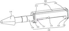
图4为本实用新型电子触控笔一实施例的局部剖面图;FIG4 is a partial cross-sectional view of an embodiment of the electronic touch pen of the present invention;
图5为本实用新型电子触控笔一实施例的外观展示图。FIG. 5 is a diagram showing the appearance of an electronic touch pen according to an embodiment of the present invention.
附图标号说明:Description of Figure Numbers:


本实用新型目的的实现、功能特点及优点将结合实施例,参照附图做进一步说明。The realization of the purpose, functional features and advantages of the utility model will be further explained in conjunction with embodiments and with reference to the accompanying drawings.
具体实施方式DETAILED DESCRIPTION
下面将结合本实用新型实施例中的附图,对本实用新型实施例中的技术方案进行清楚、完整地描述,显然,所描述的实施例仅仅是本实用新型的一部分实施例,而不是全部的实施例。基于本实用新型中的实施例,本领域普通技术人员在没有作出创造性劳动前提下所获得的所有其他实施例,都属于本实用新型保护的范围。The following will be combined with the drawings in the embodiments of the utility model to clearly and completely describe the technical solutions in the embodiments of the utility model. Obviously, the described embodiments are only part of the embodiments of the utility model, not all of the embodiments. Based on the embodiments of the utility model, all other embodiments obtained by ordinary technicians in this field without creative work are within the scope of protection of the utility model.
需要说明,若本实用新型实施例中有涉及方向性指示(诸如上、下、左、右、前、后……),则该方向性指示仅用于解释在某一特定姿态(如附图所示)下各部件之间的相对位置关系、运动情况等,如果该特定姿态发生改变时,则该方向性指示也相应地随之改变。It should be noted that if the embodiments of the present invention involve directional indications (such as up, down, left, right, front, back...), the directional indications are only used to explain the relative position relationship, movement status, etc. between the components under a certain specific posture (as shown in the accompanying drawings). If the specific posture changes, the directional indication will also change accordingly.
另外,若本实用新型实施例中有涉及“第一”、“第二”等的描述,则该“第一”、“第二”等的描述仅用于描述目的,而不能理解为指示或暗示其相对重要性或者隐含指明所指示的技术特征的数量。由此,限定有“第一”、“第二”的特征可以明示或者隐含地包括至少一个该特征。另外,若全文中出现的“和/或”的含义为,包括三个并列的方案,以“A和/或B”为例,包括A方案,或B方案,或A和B同时满足的方案。另外,各个实施例之间的技术方案可以相互结合,但是必须是以本领域普通技术人员能够实现为基础,当技术方案的结合出现相互矛盾或无法实现时应当认为这种技术方案的结合不存在,也不在本实用新型要求的保护范围之内。In addition, if there are descriptions involving "first", "second", etc. in the embodiments of the utility model, the descriptions of "first", "second", etc. are only used for descriptive purposes and cannot be understood as indicating or implying their relative importance or implicitly indicating the number of technical features indicated. Therefore, the features defined as "first" and "second" may explicitly or implicitly include at least one of the features. In addition, if the meaning of "and/or" appearing in the full text is to include three parallel solutions, taking "A and/or B" as an example, it includes solution A, or solution B, or a solution that satisfies both A and B. In addition, the technical solutions between the various embodiments can be combined with each other, but it must be based on the ability of ordinary technicians in this field to implement. When the combination of technical solutions is contradictory or cannot be implemented, it should be deemed that such a combination of technical solutions does not exist and is not within the scope of protection required by the utility model.
电子触控笔是一种小笔形的工具,用来输入指令到电脑屏幕、移动设备、绘图板等具有触摸屏的设备,用户可以通过触控笔点击触控屏幕来选取文件或绘画。为实现电子触控笔良好的书写性能,电子触控笔的各电极结构件之间的距离、电极之间的信号屏蔽以及电极的尺寸大小都有比较严格的要求。An electronic stylus is a small pen-shaped tool used to input commands to a computer screen, mobile device, drawing tablet or other device with a touch screen. Users can select files or draw by clicking the touch screen with the stylus. To achieve good writing performance of the electronic stylus, there are relatively strict requirements on the distance between the electrode structures of the electronic stylus, the signal shielding between the electrodes, and the size of the electrodes.
在相关技术中,现有电子触控笔通常在内部设置应变片感应笔芯的受力程度以在显示屏划出粗细不同的笔迹,然而应变片内部的力传递结构多为平行四边形框架结构,为确保灵敏度及稳定性四边形尺寸不能做的太小,占用内部空间过大,从而造成内部空间浪费,内部空间利用率不高。In the related art, existing electronic stylus pens are usually equipped with strain gauges inside to sense the degree of force applied to the pen core so as to draw handwriting of different thicknesses on the display screen. However, the force transmission structure inside the strain gauge is mostly a parallelogram frame structure. To ensure sensitivity and stability, the size of the quadrilateral cannot be too small, which would otherwise occupy too much internal space, thereby wasting internal space and causing low utilization of the internal space.
请参阅图1至图5,本实用新型提出一种电子触控笔。Please refer to FIG. 1 to FIG. 5 , the present invention provides an electronic touch pen.
该电子触控笔包括笔壳和受力传递结构,所述笔壳100具有用于与触控屏接触时使所述触控屏产生电信号的笔芯110;所述受力传递结构设于所述笔壳100内,所述受力传递结构包括应变片200和笔芯支架120,所述笔芯支架120与所述笔芯110连接;所述应变片200包括固定段220以及分别与所述固定段220两端连接且弯折延伸出的受力段210和检测段230,所述笔芯支架120贯穿所述受力段210,且与所述受力段210和所述检测段230连接,所述检测段230上设置有应变计231;所述固定段220朝向所述笔芯110的受力方向延伸,所述固定段220焊接于所述笔壳100的内壁上。The electronic touch pen comprises a pen shell and a force transmission structure, wherein the
具体来说,应变片200是敏感受力件,应变片200受力后会产生相对明显的形变,通过应变片200贴有应变计231,能检测其变形量,从而计算出受力的大小。在笔芯110进行书写时,笔芯110受到触控屏的挤压,通过笔壳100内与笔芯110连接的笔芯支架120将力依次传递至应变片200的受力段210、固定段220、检测段230,而应变片200朝向所述笔芯110的受力方向延伸的固定段220上表面与笔壳100的内壁通过焊接固定,故应变片200的固定段220可认为是固定不动的。由于应变片200具有弹性,通过应变计231检测应变片200在检测段230产生的形变,进而计算出应变计231的形变量,进而使得电子触控笔可以根据应变计231计算得到的变形量调整在触控屏上书写笔迹的粗细。如此设置,在确保受力传递结构稳定性可靠的前提下,改善目前平行四边形框架结构,笔芯支架120贯穿应变片200的受力段210伸入应变片200的开口空间,笔芯支架120部分容置于该开口空间内,提高内部空间利用率高,留出更多空间给其余零件。Specifically, the
请参阅图1和图4,在一实施例中,所述笔芯支架120包括连接管124、第一支架121、第二支架122和第三支架123,所述连接管124与所述笔芯110连接,所述连接管124与所述第一支架121连接,所述第二支架122的两端分别垂直连接所述第一支架121和所述第三支架123;所述受力段210开设有供所述连接管124贯穿的连接孔211,所述连接管124贯穿所述连接孔211;所述第一支架121与所述受力段210连接,所述第三支架123与所述检测段230连接。如此设置,受力传递结构形成具有开口的双层框架结构,保证受力传递结构的稳定性,减少受力传递结构空间占用率。Please refer to Figures 1 and 4. In one embodiment, the
请参阅图1至图2,在一实施例中,所述第一支架121的底部延伸出第一翻边125,所述第一翻边121与所述受力段210连接;和/或,所述第三支架123的底部延伸出第二翻边126,所述第二翻边126与所述检测段230连接。可以理解的是,所述第一支架121的底部延伸出第一翻边125,所述第一翻边125与所述受力段210连接。或者,所述第三支架123的底部延伸出第二翻边126,所述第二翻边126与所述检测段230连接。或者,所述第一支架121的底部延伸出第一翻边125,所述第一翻边125与所述受力段210连接;以及所述第三支架123的底部延伸出第二翻边126,所述第二翻边126与所述检测段230连接。通过第一翻边125和第二翻边126的设置,可以提高应变片200的受力敏感度,保证应变计231的检测精度。Please refer to FIG. 1 and FIG. 2. In one embodiment, a
请参阅图3,在一实施例中,所述受力段210与所述固定段220垂直,所述检测段230与所述固定段220垂直。如此最大化利用笔壳100内部空间,减少应变片200的空间占用。当然,在其他实施例中,所述受力段210与所述固定段220之间的夹角还可以80度、70度等,所述检测段230与所述固定段220之间的夹角还可以80度、70度等。Please refer to FIG. 3 . In one embodiment, the force-bearing
请参阅图3,在一实施例中,所述受力段210、所述固定段220、所述检测段230均呈片状设置。通过方片状设置尽可能减少应变片200的体积,减少笔壳100内部空间占用。3 , in one embodiment, the force-bearing
请参阅图4,在一实施例中,所述笔壳100的内壁包括有呈环状设置的屏蔽钢管130,所述固定段220焊接于所述屏蔽钢管130的内壁上。可以理解的是,屏蔽钢管130可以起到信号屏蔽、隔离作用,降低信号发散以提高电子触控笔内电极与触控屏的信号交互能力。当笔书写的时候,笔芯110受力传递给笔芯110支架,笔芯110支架再将变形从与应变片200焊接接触的部位即受力段210传递给应变片200,而应变片200的固定段220上表面与屏蔽钢管130通过焊接刚性连接,故应变片200的平面部分即固定段220可认为是固定不动的。由于笔芯支架120刚性比应变片200好,相对变形小很多,最终可认为只有应变片200产生了变形,进而应变计231能检测出变形量。Please refer to FIG. 4 . In one embodiment, the inner wall of the
为保证设置于应变片200的应变计231检测到笔芯110受力程度的精确性,应当保证笔芯110支架的刚度,在一实施例中,所述笔芯110支架的材质采用金属材料。当然,在其他实施例中,笔芯110支架还可以采用具有一定刚性的材料。In order to ensure the accuracy of the
在一实施例中,所述笔壳100内还设有控制主板,所述控制主板与所述应变计231电连接。如此应变计231通过检测的形变量发送信号至控制主板,控制主板控制笔芯110在触控屏书写的笔迹粗细。In one embodiment, a control mainboard is further provided in the
请参阅图1和图5,在一实施例中,所述笔芯110的端部呈倒圆设置。笔芯110用于与显示屏接触的端部若为尖角设置,笔芯110应力集中,很容易划伤显示屏。通过圆角设置,使得电子触摸笔与显示屏之间接触更为平滑,防止划伤显示屏。Please refer to FIG. 1 and FIG. 5 . In one embodiment, the end of the
请参阅图1至图5,本实用新型还提出一种电子设备,该电子设备包括显示屏和电子触控笔,其中,所述显示屏用于供所述电子触控笔触控,该电子触控笔包括笔壳和受力传递结构,所述笔壳100具有用于与触控屏接触时使所述触控屏产生电信号的笔芯110;所述受力传递结构设于所述笔壳100内,所述受力传递结构包括应变片200和笔芯支架120,所述笔芯支架120与所述笔芯110连接;所述应变片200包括固定段220以及分别与所述固定段220两端连接且弯折延伸出的受力段210和检测段230,所述笔芯支架120贯穿所述受力段210,且与所述受力段210和所述检测段230连接,所述检测段230上设置有应变计231;所述固定段220朝向所述笔芯110的受力方向延伸,所述固定段220焊接于所述笔壳100的内壁上。由于本电子设备采用了上述所有实施例的全部技术方案,因此同样具有上述实施例的技术方案所带来的所有有益效果,在此不再一一赘述。Please refer to Figures 1 to 5. The utility model further proposes an electronic device, which includes a display screen and an electronic touch pen, wherein the display screen is used for being touched by the electronic touch pen, and the electronic touch pen includes a pen shell and a force transmission structure, the
以上所述仅为本实用新型的可选实施例,并非因此限制本实用新型的专利范围,凡是在本实用新型的实用新型构思下,利用本实用新型说明书及附图内容所作的等效结构变换,或直接/间接运用在其他相关的技术领域均包括在本实用新型的专利保护范围内。The above description is only an optional embodiment of the utility model, and does not limit the patent scope of the utility model. All equivalent structural changes made by using the contents of the utility model specification and drawings under the utility model concept, or directly/indirectly used in other related technical fields are included in the patent protection scope of the utility model.
Claims (10)
Translated fromChinesePriority Applications (4)
| Application Number | Priority Date | Filing Date | Title |
|---|---|---|---|
| CN202223060029.8UCN218974891U (en) | 2022-11-17 | 2022-11-17 | Electronic stylus and electronic equipment |
| PCT/CN2023/103283WO2024103741A1 (en) | 2022-11-17 | 2023-06-28 | Electronic stylus pen and electronic device |
| CN202380014379.9ACN118284868A (en) | 2022-11-17 | 2023-06-28 | Electronic stylus and electronic equipment |
| US18/658,799US12386438B2 (en) | 2022-11-17 | 2024-05-08 | Electronic stylus and electronic device |
Applications Claiming Priority (1)
| Application Number | Priority Date | Filing Date | Title |
|---|---|---|---|
| CN202223060029.8UCN218974891U (en) | 2022-11-17 | 2022-11-17 | Electronic stylus and electronic equipment |
Publications (1)
| Publication Number | Publication Date |
|---|---|
| CN218974891Utrue CN218974891U (en) | 2023-05-05 |
Family
ID=86150795
Family Applications (2)
| Application Number | Title | Priority Date | Filing Date |
|---|---|---|---|
| CN202223060029.8UActiveCN218974891U (en) | 2022-11-17 | 2022-11-17 | Electronic stylus and electronic equipment |
| CN202380014379.9APendingCN118284868A (en) | 2022-11-17 | 2023-06-28 | Electronic stylus and electronic equipment |
Family Applications After (1)
| Application Number | Title | Priority Date | Filing Date |
|---|---|---|---|
| CN202380014379.9APendingCN118284868A (en) | 2022-11-17 | 2023-06-28 | Electronic stylus and electronic equipment |
Country Status (3)
| Country | Link |
|---|---|
| US (1) | US12386438B2 (en) |
| CN (2) | CN218974891U (en) |
| WO (1) | WO2024103741A1 (en) |
Cited By (1)
| Publication number | Priority date | Publication date | Assignee | Title |
|---|---|---|---|---|
| WO2024103741A1 (en)* | 2022-11-17 | 2024-05-23 | 深圳市千分一智能技术有限公司 | Electronic stylus pen and electronic device |
Family Cites Families (8)
| Publication number | Priority date | Publication date | Assignee | Title |
|---|---|---|---|---|
| EP2813918A1 (en)* | 2013-06-11 | 2014-12-17 | Anoto AB | Electronic pen |
| US11175755B1 (en)* | 2020-06-08 | 2021-11-16 | Wacom Co., Ltd. | Input system and input method |
| TW202213041A (en)* | 2020-09-23 | 2022-04-01 | 翰碩電子股份有限公司 | Touch pen structure and trigger module |
| CN113220144B (en)* | 2021-03-15 | 2022-06-07 | 荣耀终端有限公司 | Stylus |
| CN113190127B (en)* | 2021-03-26 | 2023-07-18 | 深圳市信维通信股份有限公司 | Capacitive stylus |
| US11379058B1 (en)* | 2021-04-15 | 2022-07-05 | Microsoft Technology Licensing, Llc | Winged bracket for stylus strain gauge |
| CN113311952B (en)* | 2021-06-25 | 2025-04-01 | 中航电测仪器股份有限公司 | Pressure sensor assembly for touch pen and touch pen |
| CN218974891U (en)* | 2022-11-17 | 2023-05-05 | 深圳市千分一智能技术有限公司 | Electronic stylus and electronic equipment |
- 2022
- 2022-11-17CNCN202223060029.8Upatent/CN218974891U/enactiveActive
- 2023
- 2023-06-28CNCN202380014379.9Apatent/CN118284868A/enactivePending
- 2023-06-28WOPCT/CN2023/103283patent/WO2024103741A1/ennot_activeCeased
- 2024
- 2024-05-08USUS18/658,799patent/US12386438B2/enactiveActive
Cited By (2)
| Publication number | Priority date | Publication date | Assignee | Title |
|---|---|---|---|---|
| WO2024103741A1 (en)* | 2022-11-17 | 2024-05-23 | 深圳市千分一智能技术有限公司 | Electronic stylus pen and electronic device |
| US12386438B2 (en) | 2022-11-17 | 2025-08-12 | Shenzhen Qianfenyi Intelligent Technology Co., Ltd | Electronic stylus and electronic device |
Also Published As
| Publication number | Publication date |
|---|---|
| WO2024103741A1 (en) | 2024-05-23 |
| US20240288954A1 (en) | 2024-08-29 |
| US12386438B2 (en) | 2025-08-12 |
| CN118284868A (en) | 2024-07-02 |
Similar Documents
| Publication | Publication Date | Title |
|---|---|---|
| CN101853050B (en) | portable electronic device | |
| CN205068322U (en) | Portable electronic device and miniaturized rechargeable capacitive touch pen thereof | |
| TWI480770B (en) | Capacitive pointer | |
| CN201142063Y (en) | Capacitive touch control pen | |
| CN218974891U (en) | Electronic stylus and electronic equipment | |
| WO2012040913A1 (en) | Pen head configuration structure for capacitive touch-screen stylus pen | |
| US20110267266A1 (en) | Mouse Pad with Touch Panel Pointing Device | |
| CN210691275U (en) | Stylus | |
| CN201993740U (en) | A touch screen with dual touch devices | |
| CN219016945U (en) | Nib anti-shake moves structure and touch-control pen | |
| CN217467633U (en) | Touch pad, pressure touch device and electronic equipment | |
| WO2024103742A1 (en) | Electronic stylus and electronic device | |
| CN210091122U (en) | Touch control pen | |
| JP6824128B2 (en) | Touch pen and display device using it | |
| CN212367497U (en) | TWS bluetooth headset | |
| CN205656593U (en) | A new capacitive stylus | |
| CN222260026U (en) | Touch pen and electronic equipment | |
| CN210091123U (en) | Active pen with guiding bridge conduction structure | |
| CN204229373U (en) | A kind of handset touch panel with special-shaped safeguard structure | |
| CN223333343U (en) | Electronic pen | |
| CN118259764A (en) | Stylus pen and electronic device | |
| CN220603996U (en) | Stylus | |
| CN222600187U (en) | Touch pen and electronic equipment assembly | |
| TW201019178A (en) | Sensing structure and displayer comprising the same | |
| CN220671936U (en) | Stylus based on metal pen core |
Legal Events
| Date | Code | Title | Description |
|---|---|---|---|
| GR01 | Patent grant | ||
| GR01 | Patent grant | ||
| CP03 | Change of name, title or address | Address after:518000 2101, building 3, Chongwen Park, Nanshan Zhiyuan, No. 3370 Liuxian Avenue, Fuguang community, Taoyuan Street, Nanshan District, Shenzhen, Guangdong Patentee after:Shenzhen Qianfenyi Intelligent Technology Co.,Ltd. Country or region after:China Address before:2101, Building 3, Chongwen Park, Nanshan Zhiyuan, No. 3370 Liuxian Avenue, Fuguang Community, Taoyuan Street, Nanshan District, Shenzhen, Guangdong Province Patentee before:MAXEYE SMART TECHNOLOGIES Co.,Ltd. Country or region before:China | |
| CP03 | Change of name, title or address |