CN218651903U - Replaceable anvil at the head end of the stapler - Google Patents
Replaceable anvil at the head end of the staplerDownload PDFInfo
- Publication number
- CN218651903U CN218651903UCN202221887840.0UCN202221887840UCN218651903UCN 218651903 UCN218651903 UCN 218651903UCN 202221887840 UCN202221887840 UCN 202221887840UCN 218651903 UCN218651903 UCN 218651903U
- Authority
- CN
- China
- Prior art keywords
- head
- buckle
- guide head
- anvil
- positioning hole
- Prior art date
- Legal status (The legal status is an assumption and is not a legal conclusion. Google has not performed a legal analysis and makes no representation as to the accuracy of the status listed.)
- Active
Links
Images


Landscapes
- Portable Nailing Machines And Staplers (AREA)
Abstract
Translated fromChinese
Description
Translated fromChinese技术领域technical field
本实用新型涉及医疗器械领域,特别是涉及一种吻合器的头端可换的抵钉座。The utility model relates to the field of medical equipment, in particular to a stapler with a replaceable head end buttress.
背景技术Background technique
腔镜手术使用现代摄影技术和高科技手术器械装备,在胸/腹壁套管或微小切口下完成胸/腹内复杂手术的微创外科技术。完成腔镜手术仅需做1-3个1.5厘米的胸/腹壁小孔,手术时,将吻合器从胸/腹壁孔伸入完成手术。同时,抵钉座是吻合器的关键部件,设计合理的抵钉座能使吻合器具有更好的吻合效果。目前现有的吻合器的抵钉座有两种结构,一种抵钉座头端为平直型导向头,一种抵钉座头端为鹰嘴型导向头;其中,平直型导向头在术野清晰下进行缝合时,医生操作较为方便快捷;在术野困难下进行缝合时,难以对组织进行分离,需要医生反复调整,才能将组织分离开。与之相反,鹰嘴型导向头在术野清晰下进行缝合时,医生操作较为不便;在术野困难下进行缝合时,却更易对组织进行分离,无需医生反复调整。因市面上吻合器的抵钉座是一体成型的,故在手术过程中,医生难以根据手术的情况选择不同抵钉座结构的吻合器,给医生使用上带来了很大的局限性。Laparoscopic surgery uses modern photography technology and high-tech surgical equipment to complete complex thoracic/abdominal surgery under the thoracic/abdominal wall casing or small incision. To complete laparoscopic surgery, only 1-3 small holes of 1.5 cm in the chest/abdominal wall are required. During the operation, the stapler is inserted through the hole in the chest/abdominal wall to complete the operation. At the same time, the nail anvil is a key part of the stapler, and a properly designed nail anvil can make the stapler have a better anastomotic effect. At present, there are two structures for the anvils of the existing staplers, one is a flat guide head at the head end of the anastomotic, and the other is an olecranon-shaped guide head at the head end of the anvil; among them, the straight guide head When suturing with a clear operative field, the doctor’s operation is more convenient and quick; when suturing with a difficult operative field, it is difficult to separate the tissue, and the doctor needs repeated adjustments to separate the tissue. On the contrary, the olecranon-shaped guide head is more inconvenient for the doctor to operate when the operation field is clear; when the operation field is difficult to suture, it is easier to separate the tissue, and the doctor does not need repeated adjustments. Because the anvils of staplers on the market are integrally formed, it is difficult for doctors to choose staplers with different anvil structures according to the operation situation during the operation, which brings great limitations to doctors.
发明内容Contents of the invention
本实用新型主要解决的技术问题是提供一种吻合器的头端可换的抵钉座,能够快速更换抵钉座头部,结构简单,给医生使用上带来很大的便捷,方便操作、减少手术时间,制造成本低。The main technical problem to be solved by the utility model is to provide an anastomat with a replaceable head end of the nail seat, which can quickly replace the head of the nail seat, has a simple structure, and brings great convenience to doctors. It is convenient to operate, The operation time is reduced, and the manufacturing cost is low.
为解决上述技术问题,本实用新型采用的一个技术方案是:提供一种吻合器的头端可换的抵钉座,包括抵钉座主体和导向头,所述抵钉座主体前端具有沿横向设置的安装槽,所述抵钉座主体的上端面上开设有与安装槽连通的纵向定位孔,所述导向头的后端具有定位头,所述定位头上具有纵向设置的弹性卡接部,所述弹性卡接部包括卡扣以及连接在卡扣两侧的弹性结构,所述导向头插入安装槽内使卡扣在横向上卡接在纵向定位孔内,并且卡扣的上表面位于纵向定位孔的内部。In order to solve the above-mentioned technical problems, a technical solution adopted by the utility model is to provide a nail anvil seat with a replaceable head end of an anastomat, including a main body of the nail anvil seat and a guide head, the front end of the main body of the nail anvil seat has a The installation groove provided, the upper end surface of the main body of the nail anvil is provided with a longitudinal positioning hole communicating with the installation groove, the rear end of the guide head has a positioning head, and the positioning head has a longitudinally arranged elastic clamping part , the elastic clamping part includes a buckle and an elastic structure connected to both sides of the buckle, the guide head is inserted into the installation groove so that the buckle is locked in the longitudinal positioning hole in the transverse direction, and the upper surface of the buckle is located at Position the inside of the hole longitudinally.
在本实用新型一个较佳实施例中,所述卡扣的横截面呈弧形,所述卡扣的最高点低于纵向定位孔的上方开口。In a preferred embodiment of the present invention, the buckle has an arc-shaped cross section, and the highest point of the buckle is lower than the upper opening of the longitudinal positioning hole.
在本实用新型一个较佳实施例中,所述弹性结构为纵向朝下设置的波纹状结构。In a preferred embodiment of the present utility model, the elastic structure is a corrugated structure arranged vertically downward.
在本实用新型一个较佳实施例中,所述卡扣、弹性结构与定位头一体成型。In a preferred embodiment of the utility model, the buckle, the elastic structure and the positioning head are integrally formed.
在本实用新型一个较佳实施例中,所述安装槽的横截面呈凸字形,所述卡扣配合进入安装槽的上部分,定位头配合进入安装槽的下部分。In a preferred embodiment of the present invention, the cross-section of the installation groove is in a convex shape, the buckle fits into the upper part of the installation groove, and the positioning head fits into the lower part of the installation groove.
在本实用新型一个较佳实施例中,所述抵钉座主体的下方还设有沿横向开设的槽体。In a preferred embodiment of the present utility model, a groove body is provided on the lower side of the main body of the nail anvil seat along the transverse direction.
在本实用新型一个较佳实施例中,所述导向头为平直型导向头或鹰嘴型导向头。In a preferred embodiment of the utility model, the guide head is a straight guide head or an olecranon-shaped guide head.
本实用新型的有益效果是:本实用新型吻合器的头端可换的抵钉座,抵钉座主体和导向头为拆卸式连接,导向头通过弹性卡接部在抵钉座主体的安装槽内,实现导向头与抵钉座主体快速拆装。The beneficial effects of the utility model are: the head end of the anastomat of the utility model can replace the nail-resistance seat, the main body of the nail-resistance seat and the guide head are detachably connected, and the guide head is installed in the installation groove of the nail-resistance seat main body through the elastic clamping part. Inside, the quick disassembly and assembly of the guide head and the main body of the nail anvil can be realized.
本实用新型吻合器的头端可换的抵钉座,弹性卡接部通过卡扣和波纹状弹性结构实现弹性卡接,简化弹性结构,卡扣与纵向定位孔实现配合卡接定位,波纹状弹性结构方便提供弹性力也方便卡扣退出纵向定位孔,实现快速更换导向头。The head end of the stapler of the utility model can replace the nail seat, and the elastic clamping part realizes the elastic clamping through the buckle and the corrugated elastic structure, which simplifies the elastic structure. The elastic structure is convenient for providing elastic force and for snapping out of the longitudinal positioning hole, so as to realize quick replacement of the guide head.
本实用新型吻合器的头端可换的抵钉座,导向头适用平直型导向头或鹰嘴型导向头,通过弹性卡接部和导向头一体成型,减小零部件装配复杂程度,一体成型制造成本低,结构简单。The head end of the stapler of the utility model can replace the nail seat, and the guide head is suitable for a straight guide head or an olecranon-type guide head, and the elastic clamping part and the guide head are integrally formed to reduce the complexity of the assembly of parts. The molding manufacturing cost is low and the structure is simple.
附图说明Description of drawings
为了更清楚地说明本实用新型实施例中的技术方案,下面将对实施例描述中所需要使用的附图作简单地介绍,显而易见地,下面描述中的附图仅仅是本实用新型的一些实施例,对于本领域普通技术人员来讲,在不付出创造性劳动的前提下,还可以根据这些附图获得其它的附图,其中:In order to more clearly illustrate the technical solutions in the embodiments of the present invention, the accompanying drawings that need to be used in the description of the embodiments will be briefly introduced below. Obviously, the accompanying drawings in the following description are only some implementations of the present invention. For example, those of ordinary skill in the art can also obtain other drawings based on these drawings without creative work, wherein:
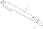
图1是本实用新型吻合器的头端可换的抵钉座一较佳实施例的立体结构示意图;Fig. 1 is a three-dimensional structural schematic diagram of a preferred embodiment of a replaceable head end of the stapler of the present invention;
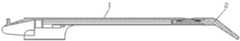
图2是图1的剖视图;Fig. 2 is a sectional view of Fig. 1;
图3是图2的局部结构示意图;Fig. 3 is a partial structural schematic diagram of Fig. 2;
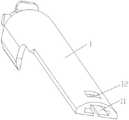
图4是鹰嘴型导向头的立体结构示意图;Fig. 4 is a three-dimensional structural schematic diagram of an olecranon-shaped guide head;
图5是抵钉座主体的立体结构示意图;Fig. 5 is a three-dimensional structural schematic diagram of the main body of the nail anvil;
图6是图5的仰视图;Fig. 6 is the bottom view of Fig. 5;
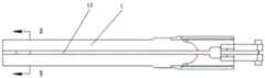
图7是图6的B-B向剖视图;Fig. 7 is the B-B direction sectional view of Fig. 6;
图8是平直型导向头的立体结构示意图;Fig. 8 is a schematic diagram of a three-dimensional structure of a straight guide head;
附图中各部件的标记如下:1、抵钉座主体,11、安装槽,12、纵向定位孔,13、槽体,2、导向头,21、定位头,22、卡扣,23、弹性结构。The marks of each part in the accompanying drawings are as follows: 1. The main body of the nail seat, 11. The installation groove, 12. The longitudinal positioning hole, 13. The groove body, 2. The guide head, 21. The positioning head, 22. The buckle, 23. The elastic structure.
具体实施方式Detailed ways
下面将对本实用新型实施例中的技术方案进行清楚、完整地描述。本说明书附图所绘示的结构、比例、大小等,均仅用以配合说明书所揭示的内容,以供熟悉此技术的人士了解与阅读,并非用以限定本实用新型可实施的限定条件,故不具技术上的实质意义,任何结构的修饰、比例关系的改变或大小的调整,在不影响本实用新型所能产生的功效及所能达成的目的下,均应仍落在本实用新型所揭示的技术内容得能涵盖的范围内。同时,本说明书中所引用的如“上”、“下”、“左”、“右”、“中间”等用语,亦仅为便于叙述的明了,而非用以限定可实施的范围,其相对关系的改变或调整,在无实质变更技术内容下,当亦视为本实用新型可实施的范畴。The technical solutions in the embodiments of the present invention will be clearly and completely described below. The structures, proportions, sizes, etc. shown in the drawings of this specification are only used to cooperate with the content disclosed in the specification, for those who are familiar with this technology to understand and read, and are not used to limit the limited conditions that the utility model can be implemented. Therefore, there is no technical substantive meaning, and any modification of structure, change of proportional relationship or adjustment of size shall still fall within the scope of the utility model without affecting the effect and the purpose of the utility model. The disclosed technical content must be within the scope covered. At the same time, terms such as "upper", "lower", "left", "right", and "middle" quoted in this specification are only for the convenience of description and are not used to limit the scope of implementation. The change or adjustment of the relative relationship should also be regarded as the applicable scope of the utility model without substantively changing the technical content.
请参阅图1至图8,一种吻合器的头端可换的抵钉座,包括抵钉座主体1和导向头2。抵钉座主体1前端具有沿横向设置的安装槽11,安装槽11的横截面呈凸字形。抵钉座主体1的上端面上开设有与安装槽11连通的纵向定位孔12。抵钉座主体1的下方还设有沿横向开设的槽体13。通过安装槽11提供导向头2的安装空间。纵向定位孔12用于定位导向头2,简化抵钉座主体1与导向头2的连接结构,降低加工难度,便于导向头2的快速定位安装。Please refer to FIG. 1 to FIG. 8 , a staple anvil with a replaceable head end, including an anvil
导向头2的后端具有定位头21,定位头21上具有纵向设置的弹性卡接部。弹性卡接部包括卡扣22以及连接在卡扣22两侧的弹性结构23。卡扣22的横截面呈弧形,弹性结构23为纵向朝下设置的波纹状结构。卡扣22、弹性结构2与定位头21一体成型。导向头2采用一体成型结构,在安装导向头2时,将定位头21对准安装槽11的下部分,卡扣22对准安装槽11的上部分,然后将导向头2沿横向推入安装槽11内,卡扣22由于波纹状结构的作用先被安装槽11的内表面下压,卡扣22进入纵向定位孔12后波纹状结构推动卡扣22复位,卡扣22配合卡接在纵向定位孔12内,完成导向头2的安装。The rear end of the
导向头2插入安装槽11内使卡扣22在横向上卡接在纵向定位孔12内,并且卡扣22的上表面位于纵向定位孔12的内部。卡扣22的最高点低于纵向定位孔12的上方开口。卡扣22整体不会突出于纵向定位孔12,不会因为误触碰而导致导向头2被退出,之后操作者手动按压卡扣22,将卡扣22从纵向定位孔12中脱离之后,才能移出导向头2,有效防止手术中的误操作。The
导向头2为平直型导向头或鹰嘴型导向头。导向头2适用于手术中常见的平直型导向头或鹰嘴型导向头,可以实现快速替换装配,有效减少手术时间。The
区别于现有技术,本实用新型吻合器的头端可换的抵钉座,能够快速更换抵钉座头部,结构简单,给医生使用上带来很大的便捷,方便操作、减少手术时间,制造成本低。Different from the prior art, the stapler of the utility model has a replaceable anvil seat at the head end, which can quickly replace the head of the anastomotic seat, has a simple structure, brings great convenience to doctors, facilitates operation, and reduces operation time , low manufacturing cost.
以上示意性的对本实用新型及其实施方式进行了描述,该描述没有限制性,附图中所示的也只是本实用新型的实施方式之一,实际的结构并不局限于此。所以,如果本领域的普通技术人员受其启示,在不脱离本实用新型创造宗旨的情况下,不经创造性的设计出与该技术方案相似的结构方式及实施例,均应属于本实用新型的保护范围。The above schematically describes the utility model and its implementation, which is not restrictive, and what is shown in the accompanying drawings is only one implementation of the utility model, and the actual structure is not limited thereto. Therefore, if a person of ordinary skill in the art is inspired by it, and without departing from the purpose of the invention of the utility model, without creatively designing a structural mode and an embodiment similar to the technical solution, it shall belong to the utility model. protected range.
Claims (7)
Translated fromChinesePriority Applications (1)
| Application Number | Priority Date | Filing Date | Title |
|---|---|---|---|
| CN202221887840.0UCN218651903U (en) | 2022-07-22 | 2022-07-22 | Replaceable anvil at the head end of the stapler |
Applications Claiming Priority (1)
| Application Number | Priority Date | Filing Date | Title |
|---|---|---|---|
| CN202221887840.0UCN218651903U (en) | 2022-07-22 | 2022-07-22 | Replaceable anvil at the head end of the stapler |
Publications (1)
| Publication Number | Publication Date |
|---|---|
| CN218651903Utrue CN218651903U (en) | 2023-03-21 |
Family
ID=85552479
Family Applications (1)
| Application Number | Title | Priority Date | Filing Date |
|---|---|---|---|
| CN202221887840.0UActiveCN218651903U (en) | 2022-07-22 | 2022-07-22 | Replaceable anvil at the head end of the stapler |
Country Status (1)
| Country | Link |
|---|---|
| CN (1) | CN218651903U (en) |
- 2022
- 2022-07-22CNCN202221887840.0Upatent/CN218651903U/enactiveActive
Similar Documents
| Publication | Publication Date | Title |
|---|---|---|
| US9480474B2 (en) | Linear cutting element with E-shaped guiding element | |
| CN101040784B (en) | Surgical stapler shaft cover | |
| JP4495212B2 (en) | Intervertebral implant | |
| CN108652695A (en) | Surgical instruments | |
| CN213249400U (en) | Stapler nail box and stapler | |
| WO2019114495A1 (en) | Staple cartridge assembly and medical stapler using same | |
| CN218651903U (en) | Replaceable anvil at the head end of the stapler | |
| CN104173088A (en) | Cut stapler | |
| JP2017500155A (en) | Straight suture cutting device | |
| WO2024104196A1 (en) | Staple cartridge assembly for surgical instrument and surgical instrument | |
| CN104248458A (en) | Suturing nail bin structure of linear anastomat | |
| WO2021047366A1 (en) | Stapler having stable jaw locking function | |
| CN209661714U (en) | Nail bin and surgical operating instrument for surgical operating instrument | |
| CN215079128U (en) | Endoscope anastomat | |
| CN220275666U (en) | Puncture device | |
| CN217472016U (en) | Intercondylar osteotomy guides and orthopedic surgical instruments | |
| CN204446068U (en) | Breastbone close holder | |
| CN211674434U (en) | Cut bone guider | |
| CN206080601U (en) | A guiding device for scope cutting closer | |
| CN210249944U (en) | Suturing nail forming part and surgical anastomat | |
| CN208447681U (en) | The nail bin of linear anastomat keeps component | |
| CN103720499B (en) | Straight line stitching instrument cutter sweep | |
| CN223350249U (en) | A nail magazine assembly with a detachable eagle beak | |
| CN119791756B (en) | Separation assembly for a surgical instrument and surgical instrument | |
| CN109984820B (en) | Coreless puncture outfit |
Legal Events
| Date | Code | Title | Description |
|---|---|---|---|
| GR01 | Patent grant | ||
| GR01 | Patent grant | ||
| CP03 | Change of name, title or address | Address after:213000 Jiangsu Province Changzhou City Longcheng Avenue 2188 Patentee after:Shengyi'an (Changzhou) Medical Technology Co.,Ltd. Country or region after:China Address before:213000 Jiangsu Province Changzhou City Longcheng Avenue 2188 Patentee before:Changzhou Haiers Medical Devices Co.,Ltd. Country or region before:China |