CN218512933U - Touch panel and display device - Google Patents
Touch panel and display deviceDownload PDFInfo
- Publication number
- CN218512933U CN218512933UCN202222416956.2UCN202222416956UCN218512933UCN 218512933 UCN218512933 UCN 218512933UCN 202222416956 UCN202222416956 UCN 202222416956UCN 218512933 UCN218512933 UCN 218512933U
- Authority
- CN
- China
- Prior art keywords
- touch
- lead
- electrode
- electrodes
- touch panel
- Prior art date
- Legal status (The legal status is an assumption and is not a legal conclusion. Google has not performed a legal analysis and makes no representation as to the accuracy of the status listed.)
- Active
Links
Images


Landscapes
- Position Input By Displaying (AREA)
Abstract
Translated fromChinese
Description
Translated fromChinese技术领域technical field
本申请涉及触控技术领域,尤其涉及一种触控面板和显示装置。The present application relates to the field of touch technology, in particular to a touch panel and a display device.
背景技术Background technique
触控面板是一种常见的显示面板,广泛应用于手机屏幕以及电脑显示器等领域。触控面板包括控制器和触控电极层;触控电极层包括呈多行多列排布的多个触控电极,每个触控电极均通过一个触控引线连接控制器。然而,触控面板的均一性差,影响触控面板的触控效果。The touch panel is a common display panel, which is widely used in fields such as mobile phone screens and computer monitors. The touch panel includes a controller and a touch electrode layer; the touch electrode layer includes a plurality of touch electrodes arranged in multiple rows and columns, and each touch electrode is connected to the controller through a touch lead. However, the poor uniformity of the touch panel affects the touch effect of the touch panel.
实用新型内容Utility model content
鉴于上述问题,本申请实施例提供一种触控面板和显示装置,用以解决触控面板的均一性差,影响触控面板触控效果的问题。In view of the above problems, the embodiments of the present application provide a touch panel and a display device to solve the problem that the touch panel has poor uniformity and affects the touch effect of the touch panel.
为了实现上述目的,本申请实施例提供如下技术方案:In order to achieve the above purpose, the embodiment of the present application provides the following technical solutions:
本申请实施例的第一方面提供一种触控面板,包括控制器、触控电极层和多条触控引线;The first aspect of the embodiments of the present application provides a touch panel, including a controller, a touch electrode layer, and a plurality of touch leads;
所述触控电极层包括同层设置的多个触控电极,各所述触控电极各通过一条所述触控引线连接所述控制器;The touch electrode layer includes a plurality of touch electrodes arranged on the same layer, and each of the touch electrodes is connected to the controller through one of the touch leads;
所述多条触控引线同层设置,且所述多条触控引线与所述触控电极层异层设置;在所述多条触控引线中,任意两条所述触控引线的线长之差小于或等于线长最长的所述触控引线线长的10%。The plurality of touch leads are arranged in the same layer, and the plurality of touch leads are arranged in different layers from the touch electrode layer; among the plurality of touch leads, any two lines of the touch leads The length difference is less than or equal to 10% of the length of the touch lead wire with the longest wire length.
本申请实施例的触控面板,通过将多条触控引线同层设置,并将多条触控引线与触控电极层异层设置,从而减小布置于触控电极层的多个触控电极与多个触控引线相互干扰的可能性;在多条触控引线中,任意两条触控引线的线长之差小于或等于线长最长的触控引线线长的10%,以保证多条触控引线的线长更加均匀,相对于相关技术的触控面板,本申请实施例的触控面板能够减小触控引线之间电阻的差异,提高了触控面板的均一性,改善触控面板触控效果。In the touch panel of the embodiment of the present application, by arranging a plurality of touch leads on the same layer, and arranging the plurality of touch leads and the touch electrode layer in different layers, thereby reducing the number of touch electrodes arranged on the touch electrode layer. The possibility of mutual interference between electrodes and multiple touch leads; among multiple touch leads, the difference between the lengths of any two touch leads is less than or equal to 10% of the length of the longest touch lead, and Ensure that the lengths of multiple touch leads are more uniform. Compared with the touch panel of the related art, the touch panel of the embodiment of the present application can reduce the difference in resistance between the touch leads and improve the uniformity of the touch panel. Improve touch panel touch effect.
在一种可能的实现方式中,所述触控引线包括引线主体和引出部,所述引线主体与所述触控电极层异层设置,所述引线主体的第一端连接所述控制器,所述引线主体的第二端通过所述引出部连接对应的所述触控电极。In a possible implementation manner, the touch lead includes a lead body and a lead-out part, the lead body is arranged in a different layer from the touch electrode layer, the first end of the lead body is connected to the controller, The second end of the lead body is connected to the corresponding touch electrode through the lead-out portion.
在一种可能的实现方式中,多个所述触控电极呈多行多列排布,沿所述触控电极的列方向,所述控制器与所述触控电极层间隔设置。In a possible implementation manner, the plurality of touch electrodes are arranged in multiple rows and columns, and the controller is spaced apart from the touch electrode layer along the column direction of the touch electrodes.
在一种可能的实现方式中,所述多条触控引线的线长相同;In a possible implementation manner, the wire lengths of the multiple touch wires are the same;
优选的,在所述列方向上,距离所述控制器最远一行中各所述触控电极所连接的所述引线主体为直线型引线主体;其余行中所述触控电极所连接的所述引线主体为折线型引线主体,所述折线型引线主体包括多个延伸部,以及至少一个连接部,多个所述延伸部均沿所述列方向延伸,多个所述延伸部沿所述触控电极的行方向间隔排列;所述连接部沿所述行方向延伸,并连接相邻的两个所述延伸部;Preferably, in the column direction, the lead bodies connected to the touch electrodes in the row farthest from the controller are linear lead bodies; the lead bodies connected to the touch electrodes in the remaining rows The lead body is a folded line lead body, and the folded line lead body includes a plurality of extension parts and at least one connecting part, and the plurality of extension parts extend along the column direction, and the plurality of extension parts extend along the row direction. The row direction of the touch electrodes is arranged at intervals; the connection part extends along the row direction and connects two adjacent extension parts;
优选的,同一所述折线型引线主体中,所述延伸部和所述连接部一体成型。Preferably, the extending part and the connecting part are integrally formed in the same broken-line lead body.
在一种可能的实现方式中,在所述行方向上,同一行中各所述触控电极所连接的所述引线主体间隔设置。In a possible implementation manner, in the row direction, the lead bodies connected to the touch electrodes in the same row are arranged at intervals.
在一种可能的实现方式中,还包括绝缘层,所述绝缘层设置于所述触控电极层的表面,所述绝缘层容置各所述触控引线。In a possible implementation manner, an insulating layer is further included, the insulating layer is disposed on the surface of the touch electrode layer, and the insulating layer accommodates each of the touch lead wires.
在一种可能的实现方式中,所述多个触控电极与显示面板的显示区对应,各所述触控引线在所述显示区的正投影位于所述显示区内。In a possible implementation manner, the plurality of touch electrodes correspond to a display area of a display panel, and an orthographic projection of each touch lead wire on the display area is located in the display area.
在一种可能的实现方式中,所述触控电极与所述触控引线正对的区域设置有沟槽。In a possible implementation manner, a groove is provided in a region where the touch electrode is directly opposite to the touch lead.
在一种可能的实现方式中,距离所述控制器最远的所述触控电极的所述沟槽数量设置为一个,沿所述触控引线的延伸方向,所述沟槽的长度小于所述触控电极的长度;In a possible implementation manner, the number of the grooves of the touch electrode farthest from the controller is set to one, and along the extending direction of the touch leads, the length of the grooves is less than the the length of the touch electrode;
其余行中各所述触控电极均包括间隔设置的多个电极单体和连接桥,所述沟槽设置于相邻的两个所述电极单体之间,相邻的两个所述电极单体通过所述连接桥连通。Each of the touch electrodes in the remaining rows includes a plurality of electrode monomers and connecting bridges arranged at intervals, the groove is arranged between two adjacent electrode monomers, and the two adjacent electrodes The monomers are connected through the connecting bridge.
本申请实施例的第二方面提供一种显示装置,其包括上述触控面板。A second aspect of the embodiments of the present application provides a display device, which includes the above-mentioned touch panel.
本申请实施例提供了一种显示装置,由于包括上述任一项所述的触控面板,因此该显示装置包括上述任一项所述的触控面板的优点,具体可参见上文相关描述,在此不再赘述。An embodiment of the present application provides a display device. Since it includes the touch panel described in any one of the above, the display device includes the advantages of the touch panel described in any one of the above. For details, please refer to the relevant description above. I won't repeat them here.
附图说明Description of drawings
为了更清楚地说明本申请实施例或现有技术中的技术方案,下面将对实施例或现有技术描述中所需要使用的附图作一简单地介绍,显而易见地,下面描述中的附图是本申请的一些实施例,对于本领域普通技术人员来讲,在不付出创造性劳动的前提下,还可以根据这些附图获得其他的附图。In order to more clearly illustrate the technical solutions in the embodiments of the present application or the prior art, the following will briefly introduce the drawings that need to be used in the description of the embodiments or the prior art. Obviously, the accompanying drawings in the following description These are some embodiments of the present application. Those skilled in the art can also obtain other drawings based on these drawings without creative work.
图1为本申请实施例提供的相关技术中的触控面板结构示意图;FIG. 1 is a schematic structural diagram of a touch panel in the related art provided by an embodiment of the present application;
图2为本申请实施例提供的包括触控面板的显示装置的结构示意图;FIG. 2 is a schematic structural diagram of a display device including a touch panel provided by an embodiment of the present application;
图3为本申请实施例提供的图2中A-A视角的剖视图;Fig. 3 is a cross-sectional view of the A-A perspective in Fig. 2 provided by the embodiment of the present application;
图4为本申请实施例提供的同一列中各触控电极对应的引线主体的结构示意图;FIG. 4 is a schematic structural diagram of the main bodies of the leads corresponding to the touch electrodes in the same column provided by the embodiment of the present application;
图5为本申请实施例提供的触控电极行数为50时,各触控电极对应的引线主体的结构示意图;FIG. 5 is a schematic structural diagram of the lead body corresponding to each touch electrode when the number of touch electrode rows provided by the embodiment of the present application is 50;
图6为本申请实施例提供的第五行中触控电极的结构示意图;FIG. 6 is a schematic structural diagram of the touch electrodes in the fifth row provided by the embodiment of the present application;
图7为本申请实施例提供的第一行中触控电极的结构示意图;FIG. 7 is a schematic structural diagram of the touch electrodes in the first row provided by the embodiment of the present application;
图8为本申请实施例提供的第一行中触控电极的另一种结构示意图。FIG. 8 is another schematic diagram of the structure of the touch electrodes in the first row provided by the embodiment of the present application.
附图标记说明:Explanation of reference signs:
100、触控电极层;100. Touch electrode layer;
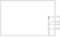
110、触控电极;111、电极单体;112、连接桥;113、沟槽;114、引出点;110. Touch electrode; 111. Electrode monomer; 112. Connection bridge; 113. Groove; 114. Lead-out point;
200、触控引线;200. Touch lead wire;
210、引出部;220、直线型引线主体;230、折线型引线主体;231、延伸部;231a、第一延伸部;231b、第二延伸部;231c、第三延伸部;231d、第四延伸部;231e、第五延伸部;231f、第六延伸部;231g、第七延伸部;231h、第八延伸部;231i、第九延伸部;231j、第十延伸部;232、连接部;232a、第一连接部;232b、第二连接部;232c、第三连接部;232d、第四连接部;232e、第五连接部;233f、第六连接部;210, lead-out part; 220, linear lead main body; 230, broken-line lead main body; 231, extension part; 231a, first extension part; 231b, second extension part; 231c, third extension part; 231d,
300、绝缘层;300, insulating layer;
400、控制器;400. Controller;
500、显示面板;500. Display panel;
510、显示区;520、非显示区。510, display area; 520, non-display area.
具体实施方式Detailed ways
正如背景技术所述,如图1所示,相关技术中触控面板包括控制器400(IntegratedCircuit,简称为IC)和触控电极层100;触控电极层100包括呈多行多列排布的多个触控电极110,各触控电极110各通过一个触控引线200连接控制器400,各触控引线200均设置为直线型触控引线,从而能够通过直线型触控引线向控制器400传输来自各触控电极的电信号。As described in the background, as shown in FIG. 1 , the touch panel in the related art includes a controller 400 (Integrated Circuit, referred to as IC) and a
然而,由于各触控电极与控制器之间的距离存在差异,使得用于连接触控电极和控制器的触控引线长度不同,在多个触控引线中,线长最长的触控引线与线长最短的触控引线的线长之差会超过线长最长的触控引线线长的50%,且各触控引线的截面面积相同,从而使线长不同的触控引线之间的电阻差异较大,进而对触控引线所传输至控制器的电信号强度产生影响,使得触控面板的均一性差,影响触控面板的触控效果。However, due to the difference in the distance between each touch electrode and the controller, the lengths of the touch wires used to connect the touch electrodes and the controller are different. Among the multiple touch wires, the touch wire with the longest wire length The difference between the length of the touch wire with the shortest wire length and the length of the touch wire with the longest wire length will exceed 50% of the length of the touch wire with the longest wire length, and the cross-sectional area of each touch wire is the same, so that the difference between the touch wires with different wire lengths The resistance of the touch panel has a large difference, which in turn affects the strength of the electrical signal transmitted to the controller by the touch lead wire, which makes the uniformity of the touch panel poor and affects the touch effect of the touch panel.
针对上述技术问题,本申请实施例提供一种触控面板和显示装置,通过将多条触控引线同层设置,并将多条触控引线与触控电极层异层设置,从而减小布置于触控电极层的多个触控电极与多个触控引线产生相互干扰的可能性;在多条触控引线中,任意两条触控引线的线长之差小于或等于线长最长的触控引线线长的10%,以使多条触控引线的线长更加均匀,从而相对于相关技术中触控面板所应用的直线型触控引线,本申请实施例的触控面板能够减小多条触控引线之间电阻的差异,提高了触控面板的均一性,改善触控面板触控效果。In view of the above technical problems, the embodiment of the present application provides a touch panel and a display device, by arranging a plurality of touch leads in the same layer, and arranging a plurality of touch leads and touch electrode layers in different layers, thereby reducing the layout The possibility of mutual interference between multiple touch electrodes and multiple touch leads on the touch electrode layer; among multiple touch leads, the difference between the lengths of any two touch leads is less than or equal to the longest line length 10% of the length of the touch leads, so that the lengths of the multiple touch leads are more uniform, so that compared with the linear touch leads used in the touch panel in the related art, the touch panel of the embodiment of the present application can The resistance difference between multiple touch leads is reduced, the uniformity of the touch panel is improved, and the touch effect of the touch panel is improved.
为了使本申请实施例的上述目的、特征和优点能够更加明显易懂,下面将结合本申请实施例中的附图,对本申请实施例中的技术方案进行清楚、完整地描述。显然,所描述的实施例仅仅是本申请的一部分实施例,而不是全部的实施例。基于本申请中的实施例,本领域普通技术人员在没有作出创造性劳动的前提下所获得的所有其它实施例,均属于本申请保护的范围。In order to make the above objects, features and advantages of the embodiments of the present application more obvious and understandable, the technical solutions in the embodiments of the present application will be clearly and completely described below in conjunction with the drawings in the embodiments of the present application. Apparently, the described embodiments are only some of the embodiments of the present application, rather than all the embodiments. All other embodiments obtained by persons of ordinary skill in the art based on the embodiments in the present application without creative efforts shall fall within the protection scope of the present application.
参照图2和图3,本申请实施例提供一种触控面板,包括控制器400、触控电极层100和多条触控引线200;触控电极层100包括同层设置的多个触控电极110,各触控电极110各通过一条触控引线200连接控制器400,以通过触控引线200向控制器400传输来自触控电极110的电信号。多条触控引线200同层设置,且多条触控引线200与触控电极层100异层设置,以减小触控电极110与触控引线200产生相互干扰的可能性;在多条触控引线200中,任意两条触控引线200的线长之差小于或等于线长最长的触控引线200线长的10%,以使多条触控引线200的线长更加均匀,减小了多条触控引线200之间电阻的差异。2 and 3, the embodiment of the present application provides a touch panel, including a
参照图3,在本申请实施例的一些实现方式中,触控面板为自容性触控面板,触控面板还包括绝缘层300,绝缘层300与触控电极层100层叠设置,绝缘层300容置各触控引线200,以使触控引线200能够与触控电极110异层设置。绝缘层300可以设置于触控电极层100的第一表面或第二表面,示例性的,在显示装置中,绝缘层300可以设置在触控电极层100靠近显示面板500的表面,或者,绝缘层300还可以设置在触控电极层100背离显示面板500的表面。Referring to FIG. 3 , in some implementations of the embodiments of the present application, the touch panel is a self-capacitive touch panel, and the touch panel further includes an insulating
参照图2和图3,触控引线200包括引线主体和引出部210,引线主体与触控电极层100异层设置,引线主体的第一端连接控制器400,引线主体的第二端通过引出部210连接对应的触控电极110。各引出部210的延伸方向均平行设置,示例性的,各引出部210的延伸方向均垂直于触控电极层100,以缩短引出部210的长度,减小引出部210的电阻。Referring to FIG. 2 and FIG. 3 , the
示例性的,多个触控电极110呈多行多列排布,沿触控电极110的列方向,控制器400与触控电极层100间隔设置,从而使同一行中各触控电极110与控制器400之间均设置有相同的距离,且设置于不同行的触控电极110与控制器400之间的距离不同。Exemplarily, a plurality of
图2为触控电极层100与触控引线200的位置示意图,如图2所示,在图2中的触控电极层100内,触控电极110呈五行三列排布,示例性的,每个触控电极110均呈方形板状,且触控电极110的长度方向平行于触控电极110的行方向。FIG. 2 is a schematic diagram of the position of the
在触控电极110的行方向上,同一行中各触控电极110所连接的引线主体间隔设置,同一列中各触控电极110所连接的引线主体按照对应触控电极110与控制器400距离远离的顺序依次排列,以使绝缘层300内多个触控引线200的排布更加均匀。In the row direction of the
参照图2和图3,多个触控电极110与显示面板500的显示区510对应,各触控引线200在显示区510的正投影位于显示区510内,从而使各触控引线200无需设置于显示面板500的非显示区520,以保证显示面板500的显示区510面积,减小非显示区520所对应的显示装置边框区域的面积。2 and 3, a plurality of
继续参照图2和图3,在本申请实施例的一些实现方式中,多条触控引线200的线长相同,以使各触控引线200的电阻相同。示例性的,各触控电极110均设置有引出点114,引出点114用于连接引出部210,在触控电极110的列方向上,各引出点114均设置在触控电极110的中部,以保证各触控引线200的长度相同。Continuing to refer to FIG. 2 and FIG. 3 , in some implementations of the embodiments of the present application, the lengths of the multiple touch leads 200 are the same, so that the resistance of each
在触控电极110的列方向上,距离控制器400最远一行中各触控电极110所连接的引线主体为直线型引线主体220,直线型引线主体220的延伸方向平行于列方向。其余行中触控电极110所连接的引线主体为折线型引线主体230,折线型引线主体230包括多个延伸部231和连接部232,多个延伸部231均沿列方向延伸,多个延伸部231沿行方向间隔排列,连接部232沿行方向延伸,并连接相邻的两个延伸部231,从而使多个延伸部231能够通过连接部232相连接。示例性的,同一折线型引线主体230中,延伸部231和连接部232一体成型,以使折线型引线主体230的形成过程更加方便。In the column direction of the
如图2和图4所示,在图中的触控电极层100内,按照距离控制器400由近及远的顺序,五行触控电极110分别为第一行、第二行、第三行、第四行和第五行。第五行中各触控电极110所连接的引线主体为直线型引线主体220,其余行中各触控电极110所连接的引线主体为折线型引线主体230。As shown in FIG. 2 and FIG. 4 , in the
第一行中触控电极110所连接的折线型引线主体230包括三个延伸部231和两个连接部232,其中,三个延伸部231分别为第一延伸部231a、第二延伸部231b和第三延伸部231c,两个连接部232分别为第一连接部232a和第二连接部232b。在触控电极110的列方向上,第一延伸部231a的一端连接引出部210,另一端沿靠近控制器400的方向延伸,并通过第一连接部232a连接第二延伸部231b,第二延伸部231b远离第一连接部232a的一端沿远离控制器400的方向延伸至第二行与第三行之间,并通过第二连接部232b连接第三延伸部231c,第三延伸部231c远离第二连接部232b的一端连接于控制器400。The
第二行中触控电极110所连接的折线型引线主体230包括两个延伸部231和一个连接部232,其中,两个延伸部231分别为第四延伸部231d和第五延伸部231e,一个连接部232为第三连接部232c。在触控电极110的列方向上,第四延伸部231d的一端连接引出部210,另一端沿远离控制器400的方向延伸至第三行与第四行之间,并通过第三连接部232c连接第五延伸部231e,第五延伸部231e远离第三连接部232c的一端连接于控制器400。The
第三行中触控电极110所连接的折线型引线主体230包括三个延伸部231和两个连接部232,其中,三个延伸部231分别为第六延伸部231f、第七延伸部231g和第八延伸部231h,两个连接部232分别为第四连接部232d和第五连接部232e。在触控电极110的列方向上,第六延伸部231f的一端连接引出部210,另一端沿靠近控制器400的方向延伸,并通过第四连接部232d连接第七延伸部231g,第七延伸部231g远离第四连接部232d的一端沿远离控制器400的方向延伸至第三行与第四行之间,并通过第五连接部232e连接第八延伸部231h,第八延伸部231h远离第五连接部232e的一端连接于控制器400。The
第四行中触控电极110所连接的折线型引线主体230包括两个延伸部231和一个连接部232,其中,两个延伸部231分别为第九延伸部231i和第十延伸部231j,一个连接部232为第六连接部232f。在触控电极110的列方向上,第九延伸部231i的一端连接引出部210,另一端沿远离控制器400的方向延伸至第四行与第五行之间,并通过第六连接部232f连接第十延伸部231j,第十延伸部231j远离第六连接部232f的一端连接于控制器400。The
第五行中触控电极110所连接的直线型引线主体220一端连接引出部210,另一端连接控制器400,第五行中触控电极110所连接的直线型引线主体220的长度等于第一行、第二行、第三行和第四行中触控电极110所连接的折线型引线主体230的长度。One end of the linear
容易理解的是,延伸部231的数量可以根据触控电极110与控制器400之间的距离确定,或者,延伸部231的数量还可以根据同一折线型引线主体230内每个延伸部231的长度确定,只要能够保证各触控引线200的长度相同即可。It is easy to understand that the number of
当触控电极110部分区域与触控引线200正对设置时,例如,多个触控电极110与显示面板500的显示区510对应,各触控引线200在显示区510的正投影位于显示区510内,使得至少部分触控电极110对应于触控引线200,从而在触控电极110与触控引线200之间形成寄生电容,进而影响触控电极110的正常使用。When the partial area of the
在本申请实施例的一些实现方式中,如图5所示,在图5中的触控电极层100内,触控电极110的行数大于5。例如,触控电极110的行数设置为50时,按照距离控制器400由近及远的顺序,第五十行中触控电极110所连接的引线主体设置为直线型引线主体220,且第四十九行中触控电极110所连接的引线主体也可以设置为直线型引线主体220。In some implementations of the embodiments of the present application, as shown in FIG. 5 , in the
容易理解的是,当触控电极110的行数较多时,距离控制器400最远的部分行中的触控电极110所连接的引线主体均可设置为直线型引线主体220;或者,全部触控电极110所连接的引线主体均设置为折线型引线主体230,只要能够保证任意两条触控引线200的线长之差小于或等于线长最长的触控引线200线长的10%即可,以减小不同触控引线200之间的电阻差异。It is easy to understand that when the number of rows of
参照图2-图8,在本申请实施例的一些实现方式中,触控电极110与触控引线200正对的区域设置有沟槽113,以使沟槽113对应于触控引线200,从而能够减小触控电极110与触控引线200的正对面积,减小触控电极110与触控引线200之间所形成的寄生电容。且沟槽113所对应区域小于或等于触控电极110所占区域的25%,以保证触控电极110的触控性能。Referring to FIGS. 2-8 , in some implementations of the embodiments of the present application, a
距离控制器400最远的触控电极110的沟槽113数量设置为一个,沿触控引线200的延伸方向,沟槽113的长度小于触控电极110的长度;其余行中各触控电极110均包括间隔设置的多个电极单体111和连接桥112,沟槽113设置于相邻的两个电极单体111之间,相邻的两个电极单体111通过连接桥112连通,从而通过连接桥112将多个电极单体111相连接以形成触控电极110。The number of the
示例性的,如图2和图6所示,在图6中的触控电极层100内,第一行中各触控电极110均设置有间隔设置的八个电极单体111和七个沟槽113,七个沟槽113中的每一个均对应设置于第一延伸部231a、第二延伸部231b、第三延伸部231c、第五延伸部231e、第八延伸部231h、第十延伸部231j以及直线型引线主体220中的一个。在触控引线200的列方向上,每个沟槽113的长度均等于触控电极110的长度。Exemplarily, as shown in FIG. 2 and FIG. 6, in the
第二行中各触控电极110均设置有间隔设置的八个电极单体111和七个沟槽113,七个沟槽113中的每一个均对应设置于第二延伸部231b、第三延伸部231c、第四延伸部231d、第五延伸部231e、第八延伸部231h、第十延伸部231j以及直线型引线主体220中的一个。在触控引线200的列方向上,每个沟槽113的长度均等于触控电极110的长度。Each
第三行中各触控电极110均设置有间隔设置的八个电极单体111和七个沟槽113,七个沟槽113中的每一个均对应设置于第四延伸部231d、第五延伸部231e、第六延伸部231f、第七延伸部231g、第八延伸部231h、第十延伸部231j以及直线型引线主体220中的一个。在触控引线200的列方向上,每个沟槽113的长度均等于触控电极110的长度。Each
第四行中各触控电极110均设置有间隔设置的四个电极单体111和三个沟槽113,三个沟槽113中的每一个均对应设置于第九延伸部231i、第十延伸部231j以及直线型引线主体220中的一个。在触控引线200的列方向上,每个沟槽113的长度均等于触控电极110的长度。Each
参照图6,第五行中各触控电极110均设置有一个沟槽113,在触控电极110的列方向上,沟槽113的长度小于触控电极110的长度。沟槽113的一端对应于引出点114,沟槽113的另一端沿靠近控制器400的方向延伸,设置于第五行的沟槽113对应于直线型引线主体220,以使直线型引线主体220的正交投影穿过沟槽113,减小直线型引线主体220与第五行中触控电极110所形成的寄生电容。Referring to FIG. 6 , each
参照图7和图8,在本申请实施例的一些实现方式中,在第一行、第二行、第三行和第四行,同一行中多个触控电极110的电极单体111均匀设置,在行方向上,同一行中多个触控电极110的沟槽113的宽度相同,以保证触控电极110的感应区域更加均匀。7 and 8, in some implementations of the embodiments of the present application, in the first row, second row, third row and fourth row, the electrode monomers 111 of the plurality of
示例性的,如图7所示,以第一行中各触控电极110为例,触控电极110所设置的八个电极单体111沿触控电极110的行方向间隔排布,且在触控电极110的行方向上,每个电极单体111的长度相同,且相邻电极单体111之间所形成的沟槽113的宽度相同,以使正对于触控电极110的七个延伸部231的分布更加均匀。Exemplarily, as shown in FIG. 7, taking the
参照图8,第一行中各触控电极110还可以包括多个电极单体111,电极单体111的数量大于触控电极110所对应的延伸部231的数量,例如电极单体111的数量为十五个,沟槽113的数量为十四个,与七个延伸部231相对的七个沟槽113间隔设置。容易理解的是,当第一行、第二行、第三行、第四行中触控电极110所设置的沟槽113的数量较多时,则能够保证各延伸部231均能够对应于一个沟槽113。Referring to FIG. 8 , each
在相邻的两个电极单体111之间,连接桥112的数量可以设置为一个或多个,例如每两个相邻的电极单体111之间均设置有一个连接桥112,以减小连接桥112与延伸部231之间所形成的寄生电容。且各连接桥112均沿触控电极110的行方向延伸,以通过七个连接桥112将八个电极单体111连接。Between two adjacent electrode monomers 111, the number of connecting
在本申请实施例的一些实现方式中,在同一触控电极110中,电极单体111与连接桥112一体成型,以使触控电极110的制备过程更加方便。In some implementations of the embodiments of the present application, in the
本申请实施例提供的触控面板,通过将多条触控引线200同层设置于绝缘层300,并将多条触控引线200与触控电极层100异层设置,从而减小布置于触控电极层100的多个触控电极110与多个触控引线200产生相互干扰的可能性;多个触控电极110与显示面板500的显示区510对应,各触控引线200在显示区510的正投影均位于显示区510内,从而使各触控引线200无需设置于显示面板500的非显示区520,以保证显示面板500的显示区510面积,减小非显示区520所对应的显示装置边框区域的面积;In the touch panel provided by the embodiment of the present application, a plurality of touch leads 200 are arranged on the insulating
在多条触控引线200中,任意两条触控引线200的线长之差小于或等于线长最长的触控引线200线长的10%,以使多条触控引线200的线长更加均匀,从而相对于相关技术中触控面板所应用的直线型触控引线,本申请实施例的触控面板能够减小多条触控引线200之间电阻的差异,提高了触控面板的均一性,改善触控面板触控效果。Among the multiple touch leads 200 , the difference between the lengths of any two touch leads 200 is less than or equal to 10% of the length of the
本申请实施例的第二方面提供一种显示装置,其包括上述各实施例所述的触控面板。由于包括上述触控面板,因此该显示装置包括上述触控面板的优点,具体可参见上文相关描述,在此不再赘述。A second aspect of the embodiments of the present application provides a display device, which includes the touch panel described in the above embodiments. Since the display device includes the above-mentioned touch panel, the display device includes the advantages of the above-mentioned touch panel. For details, please refer to the relevant description above, which will not be repeated here.
一般而言,应当至少部分地由语境下的使用来理解术语。例如,至少部分地根据语境,文中使用的术语“一个或多个”可以用于描述单数的意义的任何特征、结构或特性,或者可以用于描述复数的意义的特征、结构或特性的组合。类似地,至少部分地根据语境,还可以将诸如“一”或“所述”的术语理解为传达单数用法或者传达复数用法。In general, terms should be understood at least in part by contextual usage. For example, the term "one or more" as used herein may be used to describe any feature, structure, or characteristic in the singular or may be used to describe a combination of features, structures, or characteristics in the plural, depending at least in part on the context . Similarly, terms such as "a" or "the" may also be understood to convey singular usage or to convey plural usage, depending at least in part on context.
最后应说明的是:以上各实施例仅用以说明本申请的技术方案,而非对其限制;尽管参照前述各实施例对本申请进行了详细的说明,本领域的普通技术人员应当理解:其依然可以对前述各实施例所记载的技术方案进行修改,或者对其中部分或者全部技术特征进行等同替换;而这些修改或者替换,并不使相应技术方案的本质脱离本申请各实施例技术方案的范围。Finally, it should be noted that: the above embodiments are only used to illustrate the technical solutions of the present application, and are not intended to limit it; although the application has been described in detail with reference to the foregoing embodiments, those of ordinary skill in the art should understand that: It is still possible to modify the technical solutions described in the foregoing embodiments, or perform equivalent replacements for some or all of the technical features; and these modifications or replacements do not make the essence of the corresponding technical solutions deviate from the technical solutions of the various embodiments of the present application. scope.
Claims (12)
Priority Applications (1)
| Application Number | Priority Date | Filing Date | Title |
|---|---|---|---|
| CN202222416956.2UCN218512933U (en) | 2022-09-13 | 2022-09-13 | Touch panel and display device |
Applications Claiming Priority (1)
| Application Number | Priority Date | Filing Date | Title |
|---|---|---|---|
| CN202222416956.2UCN218512933U (en) | 2022-09-13 | 2022-09-13 | Touch panel and display device |
Publications (1)
| Publication Number | Publication Date |
|---|---|
| CN218512933Utrue CN218512933U (en) | 2023-02-21 |
Family
ID=85211777
Family Applications (1)
| Application Number | Title | Priority Date | Filing Date |
|---|---|---|---|
| CN202222416956.2UActiveCN218512933U (en) | 2022-09-13 | 2022-09-13 | Touch panel and display device |
Country Status (1)
| Country | Link |
|---|---|
| CN (1) | CN218512933U (en) |
- 2022
- 2022-09-13CNCN202222416956.2Upatent/CN218512933U/enactiveActive
Similar Documents
| Publication | Publication Date | Title |
|---|---|---|
| CN112860122B (en) | Touch display device and display system | |
| CN205015875U (en) | Electronic equipment and individual layer each other holds formula touch -sensitive screen thereof | |
| CN103577005A (en) | Capacitive touch panel and module thereof | |
| CN111223436A (en) | Array substrate, display panel and display device | |
| CN112071209A (en) | Display panel and display device | |
| WO2021092993A1 (en) | Display device and terminal | |
| CN218512933U (en) | Touch panel and display device | |
| CN114115606B (en) | Touch display panel and display device | |
| CN106249454B (en) | touch monitor | |
| CN202956748U (en) | Co-connected capacitive touch panel | |
| CN112783366B (en) | Touch control display panel | |
| CN114115591A (en) | Touch structure, touch display panel and touch display device | |
| CN113672117A (en) | Display panel and mobile terminal | |
| US11853502B1 (en) | Display panel and display device having touch electrode connecting pads disposed in arc shape | |
| CN104182103A (en) | touch panel | |
| CN213690576U (en) | Touch substrate, touch display panel and display device | |
| CN111142709B (en) | Touch panel and display device | |
| CN118251769A (en) | Display panel and display module | |
| CN114911376A (en) | Touch panel and touch display device | |
| CN112578946A (en) | Touch substrate, touch display panel and display device | |
| WO2023221214A1 (en) | Touch display panel and display apparatus | |
| CN113157141B (en) | Touch substrate and display device | |
| WO2022227674A1 (en) | Color film substrate and display panel | |
| CN113986038A (en) | Touch display panel and display terminal | |
| CN112965632B (en) | Touch module and touch device |
Legal Events
| Date | Code | Title | Description |
|---|---|---|---|
| GR01 | Patent grant | ||
| GR01 | Patent grant |