CN218480483U - Portable mobile lighting lamp - Google Patents
Portable mobile lighting lampDownload PDFInfo
- Publication number
- CN218480483U CN218480483UCN202222729946.4UCN202222729946UCN218480483UCN 218480483 UCN218480483 UCN 218480483UCN 202222729946 UCN202222729946 UCN 202222729946UCN 218480483 UCN218480483 UCN 218480483U
- Authority
- CN
- China
- Prior art keywords
- lamp body
- cable
- portable mobile
- mobile lighting
- lighting fixture
- Prior art date
- Legal status (The legal status is an assumption and is not a legal conclusion. Google has not performed a legal analysis and makes no representation as to the accuracy of the status listed.)
- Active
Links
Images


Landscapes
- Arrangement Of Elements, Cooling, Sealing, Or The Like Of Lighting Devices (AREA)
- Non-Portable Lighting Devices Or Systems Thereof (AREA)
Abstract
Description
Translated fromChinese技术领域technical field
本实用新型涉及照明灯具技术领域,特别是涉及一种手提移动照明灯具。The utility model relates to the technical field of lighting fixtures, in particular to a portable mobile lighting fixture.
背景技术Background technique
目前,市面上的照明灯具可分为电池款式和外接电源款式两种,两种款式各有优点。电池款式的照明灯具内置电源,方便放置在任意地方;外接电源款式的照明灯具能够长时间稳定地提供照明,不会出现因电量不足导致照明功率下降的情况。At present, lighting fixtures on the market can be divided into two types: battery type and external power supply type, each of which has its own advantages. The battery-style lighting fixture has a built-in power supply, which is convenient to place anywhere; the lighting fixture with an external power supply can provide stable lighting for a long time, and there will be no decline in lighting power due to insufficient power.
申请号为“CN201921024534.2”的中国实用新型专利,公开了一种户外照明灯具,其包括:散热件、驱动组件、第一光学模组以及第二光学模组;还包括防水接头,该防水接头穿设散热件且与驱动组件电性连接,即防水接头的一端用于与驱动组件电性连接,防水接头的另一端用于外接电源。防水接头11可以提高整灯的防水能力。但是,这种灯具在使用过程中,电线与灯具的连接处往往最容易损坏,这是因为在布线或者移动灯具等情况下,电线经常会受到拉扯和扭转,拉扯和扭转都会影响到电线与电路板的焊点,造成焊点断裂或接触不良,从而导致灯具损坏。The Chinese utility model patent with the application number "CN201921024534.2" discloses an outdoor lighting fixture, which includes: a heat sink, a drive assembly, a first optical module, and a second optical module; it also includes a waterproof connector, the waterproof The connector passes through the heat sink and is electrically connected with the driving component, that is, one end of the waterproof connector is used for electrical connection with the driving component, and the other end of the waterproof connector is used for external power supply. The waterproof joint 11 can improve the waterproof ability of the whole lamp. However, during the use of this lamp, the connection between the wire and the lamp is often the most vulnerable to damage. This is because the wire is often pulled and twisted during wiring or moving the lamp, which will affect the wire and the circuit. The solder joints of the board, resulting in broken solder joints or poor contact, resulting in damage to the lamps.
为此,如何设计一种手提移动照明灯具,使其能够减小电线受拉扯或扭转带来的不良影响,保护电线与电路板的焊点,避免焊点断裂导致灯具损坏,这是该领域技术人员需要解决的技术问题。For this reason, how to design a portable mobile lighting fixture so that it can reduce the adverse effects of pulling or twisting the wires, protect the solder joints between the wires and the circuit board, and prevent the solder joints from breaking and causing damage to the lamps is a technology in this field. Technical problems that people need to solve.
实用新型内容Utility model content
本实用新型的目的是克服现有技术中的不足之处,提供一种手提移动照明灯具,使其能够减小电线受拉扯或扭转带来的不良影响,保护电线与电路板的焊点,避免焊点断裂导致灯具损坏,延长产品的使用寿命。The purpose of this utility model is to overcome the deficiencies in the prior art, and provide a portable mobile lighting fixture, which can reduce the adverse effects of pulling or twisting the wires, protect the solder joints between the wires and the circuit board, and avoid Broken solder joints lead to damage to lamps, prolonging the service life of the product.
本实用新型的目的是通过以下技术方案来实现的:The purpose of this utility model is achieved through the following technical solutions:
一种手提移动照明灯具,其包括:灯具本体、电缆线以及防护组件,所述灯具本体包括电源外壳,所述电源外壳设有容置内腔和电路板,所述电路板收容于所述容置内腔中,所述电缆线穿设于所述电源外壳并与所述电路板连接,所述防护组件套设于所述电缆线上;A portable mobile lighting fixture, which includes: a lamp body, cables and protective components, the lamp body includes a power supply housing, the power supply housing is provided with an accommodating inner cavity and a circuit board, and the circuit board is accommodated in the housing placed in the inner cavity, the cable is passed through the power shell and connected to the circuit board, and the protective component is sleeved on the cable;
所述防护组件包括:防拉圈、护线密封套以及压紧螺块,所述电源外壳上设有穿线筒,所述穿线筒的底壁上开设有通孔,所述防拉圈套设于所述电缆线上并压持于所述通孔的边缘,所述护线密封套套设于所述电缆线上,所述压紧螺块与所述穿线筒螺纹连接,且所述压紧螺块将所述护线密封套压持于所述穿线筒内。The protection component includes: an anti-pull ring, a sealing sleeve for protecting wires and a compression screw block. The cable is pressed and held on the edge of the through hole, the protective wire sealing sleeve is sleeved on the cable, the compression screw is screwed to the threading barrel, and the compression screw The block presses and holds the grommet gland in the threading barrel.
在其中一个实施例中,所述防拉圈上设有多个弹性爪,多个所述弹性爪环形阵列分布于所述防拉圈上并呈现锥体状,所述弹性爪压持于所述电缆线上。In one of the embodiments, the anti-pull ring is provided with a plurality of elastic claws, and the plurality of elastic claws are distributed in an annular array on the anti-pull ring and presents a cone shape, and the elastic claws are pressed against the on the cable described above.
在其中一个实施例中,所述护线密封套包括密封部和护线延伸部,所述密封部压持于所述穿线筒的底壁,所述压紧螺块压持于所述密封部。In one of the embodiments, the grommet sealing sleeve includes a sealing part and a grommet extension part, the sealing part is pressed against the bottom wall of the threading barrel, and the compression screw is pressed against the sealing part .
在其中一个实施例中,所述防护组件包括弹性密封塞,所述弹性密封塞设于所述穿线筒的通孔处,所述电缆线穿设所述弹性密封塞,所述护线密封套的密封部压持于所述弹性密封塞。In one of the embodiments, the protective assembly includes an elastic sealing plug, the elastic sealing plug is arranged at the through hole of the threading barrel, the cable wire passes through the elastic sealing plug, and the wire protection sealing sleeve The sealing part is pressed against the elastic sealing plug.
在其中一个实施例中,所述灯具本体包括:散热灯体、LED发光灯板、透镜以及支架,所述电源外壳安装于所述散热灯体的一侧,所述LED发光灯板安装于所述散热灯体的另一侧,所述透镜盖设于所述LED发光灯板上,所述支架设于所述散热灯体上。In one embodiment, the lamp body includes: a heat dissipation lamp body, an LED light-emitting lamp board, a lens and a bracket, the power supply housing is installed on one side of the heat dissipation lamp body, and the LED light-emitting lamp board is installed on the On the other side of the heat dissipation lamp body, the lens cover is arranged on the LED light emitting lamp board, and the bracket is arranged on the heat dissipation lamp body.
在其中一个实施例中,所述散热灯体上设有散热片,所述散热片环形阵列分布于所述散热灯体上,所述LED发光灯板贴合于所述散热灯体。In one embodiment, the heat dissipation lamp body is provided with heat dissipation fins, the heat dissipation fins are distributed in an annular array on the heat dissipation lamp body, and the LED light-emitting lamp board is attached to the heat dissipation lamp body.
在其中一个实施例中,所述散热片与所述散热灯体一体成型,所述散热片与所述散热灯体均为金属结构。In one of the embodiments, the heat sink and the heat dissipation lamp body are integrally formed, and both the heat sink and the heat dissipation lamp body are metal structures.
在其中一个实施例中,所述支架包括手提架以及平放架,所述手提架与所述平放架均通过螺栓铰接于所述散热灯体上,所述手提架上设有塑胶手位,所述平放架的底面开设有定位螺孔。In one of the embodiments, the support includes a handstand and a flat shelf, both of which are hinged to the heat dissipation lamp body through bolts, and the handrail is provided with a plastic handle , the bottom surface of the horizontal shelf is provided with positioning screw holes.
在其中一个实施例中,所述散热灯体上设有挂钩,所述挂钩用于将所述散热灯体悬挂。In one of the embodiments, the heat dissipation lamp body is provided with a hook, and the hook is used for hanging the heat dissipation lamp body.
在其中一个实施例中,所述透镜上设有弹性网罩,所述弹性网罩为镂空结构,所述弹性网罩通过螺钉罩设于所述透镜的外侧。In one embodiment, the lens is provided with an elastic mesh cover, the elastic mesh cover is a hollow structure, and the elastic mesh cover is arranged on the outside of the lens through a screw cover.
综上,本实用新型的手提移动照明灯具,能够减小电线受拉扯或扭转带来的不良影响,保护电线与电路板的焊点,避免焊点断裂导致灯具损坏,延长产品的使用寿命。To sum up, the portable mobile lighting fixture of the present invention can reduce the adverse effects caused by pulling or twisting the wires, protect the solder joints between the wires and the circuit board, prevent the lamps from being damaged due to solder joint breakage, and prolong the service life of the product.
附图说明Description of drawings
为了更清楚地说明本实用新型实施例的技术方案,下面将对实施例中所需要使用的附图作简单地介绍,应当理解,以下附图仅示出了本实用新型的某些实施例,因此不应被看作是对范围的限定,对于本领域普通技术人员来讲,在不付出创造性劳动的前提下,还可以根据这些附图获得其他相关的附图。In order to more clearly illustrate the technical solutions of the embodiments of the present invention, the following drawings will be briefly introduced in the embodiments. It should be understood that the following drawings only show some embodiments of the present invention. Therefore, it should not be regarded as a limitation on the scope. For those skilled in the art, other related drawings can also be obtained according to these drawings without creative work.
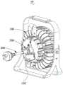
图1为本实用新型的手提移动照明灯具的结构示意图(一);Fig. 1 is the structural representation (1) of portable mobile lighting fixture of the present utility model;
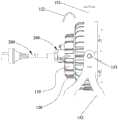
图2为图1所示的手提移动照明灯具的分解示意图;Fig. 2 is an exploded schematic view of the portable mobile lighting fixture shown in Fig. 1;
图3为图2所示的防护组件的分解示意图;Fig. 3 is an exploded schematic diagram of the protective assembly shown in Fig. 2;
图4为图1所示的手提移动照明灯具的侧视图;Fig. 4 is a side view of the portable mobile lighting fixture shown in Fig. 1;
图5为图3所示的防拉圈的结构示意图;Fig. 5 is a schematic structural view of the pull ring shown in Fig. 3;
图6为图3所示的防拉圈与电缆线的配合关系示意图;Fig. 6 is a schematic diagram of the cooperative relationship between the pull ring shown in Fig. 3 and the cable;
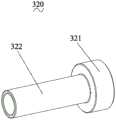
图7为图3所示的护线密封套的结构示意图;Fig. 7 is a schematic structural diagram of the wire protection sealing sleeve shown in Fig. 3;
图8为图4所示的手提移动照明灯具的剖视图;Fig. 8 is a sectional view of the portable mobile lighting fixture shown in Fig. 4;
图9为图8所示的A处的放大图;Fig. 9 is an enlarged view of A place shown in Fig. 8;
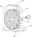
图10为本实用新型的手提移动照明灯具的结构示意图(二)。Fig. 10 is a structural schematic diagram (2) of the portable mobile lighting fixture of the present invention.
具体实施方式Detailed ways
为了便于理解本实用新型,下面将参照相关附图对本实用新型进行更全面的描述。附图中给出了本实用新型的较佳实施方式。但是,本实用新型可以以许多不同的形式来实现,并不限于本文所描述的实施方式。相反地,提供这些实施方式的目的是使对本实用新型的公开内容理解的更加透彻全面。In order to facilitate the understanding of the utility model, the utility model will be described more fully below with reference to the relevant drawings. Preferred embodiments of the utility model are provided in the accompanying drawings. However, the invention may be embodied in many different forms and is not limited to the embodiments described herein. On the contrary, the purpose of providing these embodiments is to make the disclosure of the present utility model more thorough and comprehensive.
需要说明的是,当元件被称为“固定于”另一个元件,它可以直接在另一个元件上或者也可以存在居中的元件。当一个元件被认为是“连接”另一个元件,它可以是直接连接到另一个元件或者可能同时存在居中元件。本文所使用的术语“垂直的”、“水平的”、“左”、“右”以及类似的表述只是为了说明的目的,并不表示是唯一的实施方式。It should be noted that when an element is referred to as being “fixed” to another element, it can be directly on the other element or there can also be an intervening element. When an element is referred to as being "connected to" another element, it can be directly connected to the other element or intervening elements may also be present. The terms "vertical," "horizontal," "left," "right," and similar expressions are used herein for purposes of illustration only and are not intended to represent the only embodiments.
除非另有定义,本文所使用的所有的技术和科学术语与属于本实用新型的技术领域的技术人员通常理解的含义相同。本文中在本实用新型的说明书中所使用的术语只是为了描述具体的实施方式的目的,不是旨在于限制本实用新型。本文所使用的术语“及/或”包括一个或多个相关的所列项目的任意的和所有的组合。Unless otherwise defined, all technical and scientific terms used herein have the same meaning as commonly understood by one of ordinary skill in the technical field of this invention. The terminology used herein in the description of the utility model is only for the purpose of describing specific implementations, and is not intended to limit the utility model. As used herein, the term "and/or" includes any and all combinations of one or more of the associated listed items.
本实用新型提供一种手提移动照明灯具10,如图1及图2所示,其包括:灯具本体100、电缆线200以及防护组件300,灯具本体100包括电源外壳110,电源外壳110设有容置内腔111和电路板(图未示),电路板收容于容置内腔111中,电缆线200穿设于电源外壳110并与电路板连接,防护组件300套设于电缆线200上。The utility model provides a portable
其中,如图3所示,防护组件300包括:防拉圈310、护线密封套320以及压紧螺块330,电源外壳110上设有穿线筒112,穿线筒112的底壁上开设有通孔113,防拉圈310套设于电缆线200上并压持于通孔113的边缘,护线密封套320套设于电缆线200上,压紧螺块330与穿线筒112螺纹连接,且压紧螺块330将护线密封套320压持于穿线筒112内。Wherein, as shown in FIG. 3 , the
在本实施例中,如图2及图4所示,灯具本体100包括:散热灯体120、LED发光灯板130、透镜140以及支架150,电源外壳110安装于散热灯体120的一侧,LED发光灯板130安装于散热灯体120的另一侧,透镜140盖设于LED发光灯板130上,支架150设于散热灯体120上。工作时,电缆线200外接电源,LED发光灯板130通电发光,透镜140用于将LED发光灯板130发出的光线折射,最大限度的把光利用起来,同时其也是外壳的一部份,起到保护内部LED的作用。支架150用于给灯具本体100提供支撑,方便灯具本体100的放置。In this embodiment, as shown in FIG. 2 and FIG. 4 , the
下面,对防护组件300的主要结构进行说明:Next, the main structure of the
在本实施例中,如图5及图6所示,防拉圈310上设有多个弹性爪311,多个弹性爪311环形阵列分布于防拉圈310上并呈现锥体状,当电缆线200穿过防拉圈310后,弹性爪311会压持于电缆线200上。由于多个弹性爪311呈现锥体状,该结构使得电缆线200只能单方向穿过防拉圈310,当电缆线200想反方向运动时,则弹性爪311会越夹越紧,从而限制电缆线200反向运动,具体的工作原理将在下文说明。In this embodiment, as shown in Figure 5 and Figure 6, a plurality of
如图7所示,护线密封套320包括密封部321和护线延伸部322,密封部321压持于穿线筒112的底壁,压紧螺块330压持于密封部321。工作时,护线密封套320用于保护电缆线200,压紧螺块330与穿线筒112螺纹连接后,压紧螺块330可以将护线密封套320压持固定在穿线筒112内(如图9所示)。As shown in FIG. 7 , the protective
至此,防护组件300的主要结构说明完毕。So far, the main structure of the
接下来,结合上述结构,对防护组件300的工作原理进行阐述说明:Next, in combination with the above structure, the working principle of the
如图8及图9所示,依次安装防护组件300后,电缆线200依次穿过压紧螺块330、护线密封套320、防拉圈310,最后与容置内腔111中的电路板连接,为LED发光灯板130连接电源。安装后,压紧螺块330与穿线筒112螺纹连接,压紧螺块330的一端压持于护线密封套320的密封部321,使得护线密封套320被稳定收容在穿线筒112内;防拉圈310处在容置内腔111中;As shown in Figure 8 and Figure 9, after the
当电缆线200受到轴线方向的拉扯力时,电缆线200具有向着容置内腔111外部运动的趋势,又由于防拉圈310的弹性爪311压持于电缆线200上,弹性爪311与电缆线200之间具有摩擦力。此时,向后运动的趋势会使弹性爪311进一步压持在电缆线200,使得电缆线200被夹紧而无法运动。也就是说,在防拉圈310的作用下,电缆线200只能向着电路板方向运动,而无法向着远离容置内腔111的方向运动。这样,当电缆线200受到拉扯力时,拉扯力会传递到防拉圈310上,最后作用在电源外壳110上;When the
当电缆线200受到扭转或者摇摆的扭力时,由于护线密封套320套设在电缆线200上,护线密封套320的护线延伸部322提供了一段较长距离的防护,则即使电缆线200受到扭力,但是,处在护线密封套320内的一段电缆线200仍可以保持直线,即护线密封套320保护电缆线200使其不会被过度弯曲。这样便可以减小处在连接处的电缆线200的弯曲程度,从而减小对焊点处的影响,并且减小使用过程中电缆线200的摇摆磨损。When the
要说明的是,本实用新型的防护组件300通过防拉圈310与护线密封套320的配合,使得处在容置内腔111内的电缆线200能够尽可能保持稳定,电缆线200既不会被拉扯,又不会受力摇摆;外界施加在电缆线200上的作用力都被防拉圈310与护线密封套320传递到电源外壳110上,从而使得电缆线200与电路板连接处的焊点不会受到外力作用,从而保证焊点的良好电连接。工作过程中,电缆线200可能同时受到拉扯和摇摆的力,因此防拉圈310与护线密封套320是相互配合发挥作用的;在其他实施例中,可以将防拉圈310与护线密封套320做成一体化设计。It should be noted that the
在其中一个实施例中,如图9所示,防护组件300还包括弹性密封塞340,弹性密封塞340设于穿线筒112的通孔113处,电缆线200穿设弹性密封塞340,护线密封套320的密封部321压持于弹性密封塞340。弹性密封塞340主要用于封堵电缆线200与通孔113之间的间隙,起到防水防尘的作用。In one of the embodiments, as shown in FIG. 9 , the
本实用新型的手提移动照明灯具10通过外接电源的方式,从而保持了LED发光灯板130持续满功率发光,这使得产品的发热量较大。为了使得手提移动照明灯具10能够更好地散热,在本实施例中,如图2所示,散热灯体120上设有散热片121,散热片121环形阵列分布于散热灯体120上,LED发光灯板130贴合于散热灯体120上。优先的,散热片121与散热灯体120一体成型,散热片121与散热灯体120均为金属结构。散热片121可以增大与空气的接触面积,提高热交换速率;金属结构以及一体成型的设计使得散热片121与散热灯体120之间存在良好的导热关系。工作时,LED发光灯板130产生的热量会被散热灯体120吸收,再传递给散热片121,最终散发到外界。The portable
为方便手提移动照明灯具10的放置或悬挂,在本实施例中,如图2所示,灯具本体100的支架150包括手提架151以及平放架152,手提架151与平放架152均通过螺栓153(如图4所示)铰接于散热灯体120上。手提架151可以方便灯具10进行悬挂,平放架152使得灯具10可以直接放置在平面上,并且由于通过螺栓153铰接,手提架151与散热灯体120之间的角度、平放架152与散热灯体120之间的角度都可以调节,从而改变灯具10的照射角度。In order to facilitate the placement or suspension of the portable
优选的,如图2所示,手提架151上设有塑胶手位154,平放架152的底面开设有定位螺孔155。塑胶手位154能够给用户提供更好的握感,不会有局部刺手等现象;定位螺孔155使得平放架152通过螺栓固定在其他设备上。在其中一个实施例中,散热灯体120上还设有挂钩122,挂钩122用于将散热灯体120悬挂。Preferably, as shown in FIG. 2 , a
进一步地,由于透镜140易碎易裂,为了防止在使用或搬运过程中磕碰到透镜140,在本实施例中,如图2及图10所示,透镜140上设有弹性网罩160,弹性网罩160为镂空结构,弹性网罩160通过螺钉(图未示)罩设于透镜140的外侧。镂空结构的弹性网罩160既不会影响灯具10的发光,又可以在碰撞时提供缓冲,从而使透镜140不会受到磕碰,保护了透镜140及其内的LED发光灯板130。Furthermore, since the
综上所述,本实用新型的手提移动照明灯具10,能够减小电线受拉扯或扭转带来的不良影响,保护电线与电路板的焊点,避免因焊点断裂导致的灯具10损坏,延长了产品的使用寿命。To sum up, the portable
以上所述实施例仅表达了本实用新型的几种实施方式,其描述较为具体和详细,但并不能因此而理解为对实用新型专利范围的限制。应当指出的是,对于本领域的普通技术人员来说,在不脱离本实用新型构思的前提下,还可以做出若干变形和改进,这些都属于本实用新型的保护范围。因此,本实用新型专利的保护范围应以所附权利要求为准。The above-mentioned embodiments only express several implementation modes of the utility model, and the description thereof is relatively specific and detailed, but it should not be understood as limiting the scope of the utility model patent. It should be noted that those skilled in the art can make several modifications and improvements without departing from the concept of the present invention, and these all belong to the protection scope of the present invention. Therefore, the scope of protection of the utility model patent should be based on the appended claims.
Claims (10)
Translated fromChinesePriority Applications (1)
| Application Number | Priority Date | Filing Date | Title |
|---|---|---|---|
| CN202222729946.4UCN218480483U (en) | 2022-10-14 | 2022-10-14 | Portable mobile lighting lamp |
Applications Claiming Priority (1)
| Application Number | Priority Date | Filing Date | Title |
|---|---|---|---|
| CN202222729946.4UCN218480483U (en) | 2022-10-14 | 2022-10-14 | Portable mobile lighting lamp |
Publications (1)
| Publication Number | Publication Date |
|---|---|
| CN218480483Utrue CN218480483U (en) | 2023-02-14 |
Family
ID=85169611
Family Applications (1)
| Application Number | Title | Priority Date | Filing Date |
|---|---|---|---|
| CN202222729946.4UActiveCN218480483U (en) | 2022-10-14 | 2022-10-14 | Portable mobile lighting lamp |
Country Status (1)
| Country | Link |
|---|---|
| CN (1) | CN218480483U (en) |
- 2022
- 2022-10-14CNCN202222729946.4Upatent/CN218480483U/enactiveActive
Similar Documents
| Publication | Publication Date | Title |
|---|---|---|
| US8436517B2 (en) | Light bulb | |
| US9890943B2 (en) | Thermally dissipated lighting system | |
| CN102052577A (en) | Light emitting diode lighting device | |
| JP2010198828A (en) | Lighting device | |
| CN108426202B (en) | Lighting lamp | |
| CN201844234U (en) | LED lighting device and LED lighting lamp | |
| KR101737744B1 (en) | Tubular type led lighting apparatus | |
| CN218480483U (en) | Portable mobile lighting lamp | |
| CN202065797U (en) | Light-emitting diode (LED) tube light | |
| CN103174998B (en) | Light-emitting diode (LED) illuminating device | |
| KR20120007668A (en) | Light emitting diode module | |
| EP2995848A1 (en) | Led lamp tightly supported on lamp unit by insertion of power socket | |
| JP7016219B2 (en) | Lighting equipment and lighting equipment | |
| CN215892279U (en) | Lamp driving device and lamp | |
| CN207262106U (en) | A kind of LED light | |
| CN102182960A (en) | Light emitting diode (LED) down lamp | |
| JP2013109933A (en) | Fluorescent lamp type led lighting fixture | |
| CN207990394U (en) | A kind of LED light that dustproof and waterproof is explosion-proof | |
| CN204420751U (en) | Lighting lamp | |
| CN110822347B (en) | Industrial and mineral lamp | |
| CN204573778U (en) | A LED illuminant structure installed on a lamp arm | |
| CN216557056U (en) | A LED industrial and mining cooling lamp | |
| CN212618126U (en) | A plug-in type conductive lamp holder structure | |
| JP2011070946A (en) | Lighting device | |
| CN216202604U (en) | Heat dissipation type LED lamp convenient to installation |
Legal Events
| Date | Code | Title | Description |
|---|---|---|---|
| GR01 | Patent grant | ||
| GR01 | Patent grant |