CN218335065U - Cable stripping and cutting device - Google Patents
Cable stripping and cutting deviceDownload PDFInfo
- Publication number
- CN218335065U CN218335065UCN202222621359.3UCN202222621359UCN218335065UCN 218335065 UCN218335065 UCN 218335065UCN 202222621359 UCN202222621359 UCN 202222621359UCN 218335065 UCN218335065 UCN 218335065U
- Authority
- CN
- China
- Prior art keywords
- base
- cable
- disc cutter
- disc
- hole
- Prior art date
- Legal status (The legal status is an assumption and is not a legal conclusion. Google has not performed a legal analysis and makes no representation as to the accuracy of the status listed.)
- Active
Links
Images


Landscapes
- Removal Of Insulation Or Armoring From Wires Or Cables (AREA)
Abstract
Description
Translated fromChinese技术领域technical field
本实用新型涉及电缆的切割技术领域,特别涉及一种电缆剥切装置。The utility model relates to the technical field of cable cutting, in particular to a cable stripping and cutting device.
背景技术Background technique
电缆,包括由多根互相绝缘的导线或导体绞成的缆心,以及防止缆心受潮与保护缆芯减轻机械损害的外层护套,电缆根据用途可以分为通讯电缆和电力电缆,其中,无论是通讯电缆和电力电缆,其为了保护缆芯,设有多种防护层,包括外护套、钢丝铠装、内衬层和绝缘层等等,电缆由于多种防护层的设置,在增加了对缆芯的防护效果的同时,针对电缆而进行的维修和加工也更为困难。Cables, including a cable core made of multiple insulated wires or conductors, and an outer sheath that prevents the cable core from getting wet and protects the cable core from mechanical damage. Cables can be divided into communication cables and power cables according to their uses. Among them, Whether it is a communication cable or a power cable, in order to protect the cable core, it has a variety of protective layers, including outer sheath, steel wire armor, inner lining and insulation layer, etc. Due to the setting of various protective layers, the cable is increasing While the protective effect on the cable core is reduced, the maintenance and processing of the cable are also more difficult.
现在的电缆在投入使用时,必须经过分段,而分段就涉及到去切割电缆,一般的电缆在进行切割时都是非常的简便,操作起来也是非常上手,但是由于电缆的外侧是圆柱体,所以电缆在进行切割时,经常会左摇右晃,不好进行切割。When the current cable is put into use, it must be segmented, and the segment involves cutting the cable. The general cable is very easy to cut, and the operation is very easy to use. However, because the outer side of the cable is a cylinder , so when the cable is being cut, it often shakes left and right, which is not easy to cut.
为此,部分厂家根据电缆的规格型号,相应的设置了电缆的自动剖切设备,该类设备绝大多数是沿着电缆的长度方向,对电缆的外皮进行切割。然而,此种切割方式容易因切刀的形制而造成切口的不规范,电缆剥切后的下一步加工不变,因而需要进一步的对纵切后电缆的电缆进行环切,以使电缆的切割更为规整。For this reason, some manufacturers have set up automatic cable cutting equipment according to the specifications and models of the cables. Most of these equipments cut the outer sheath of the cables along the length direction of the cables. However, this cutting method is likely to cause irregular cuts due to the shape of the cutter, and the next step of processing after cable stripping remains unchanged. Therefore, it is necessary to further cut the cable after longitudinal cutting to make the cutting of the cable More regular.
但是,两种切割方式依次使用,需要更换电缆的切割工具,其中不可避免的需要搬运沉重的电缆,使电缆的切割和对接等工作极为劳累,故而需要以一种更为合适的切割手法和切割装置来对电缆进行切割。However, the two cutting methods are used in turn, and the cutting tools of the cables need to be replaced. It is inevitable to carry heavy cables, which makes the work of cutting and docking the cables extremely tiring. Therefore, a more suitable cutting method and cutting method are required. Device to cut cables.
实用新型内容Utility model content
有鉴于此,本实用新型旨在提出一种电缆剥切装置,以提供一种便于操作,且剥切效果良好的电缆剥切设备。In view of this, the utility model aims to provide a cable stripping and cutting device to provide a cable stripping and cutting device that is easy to operate and has a good stripping and cutting effect.
为达到上述目的,本实用新型的技术方案是这样实现的:In order to achieve the above object, the technical solution of the utility model is achieved in that:
一种电缆剥切装置,包括底座,还包括:A cable stripping and cutting device, including a base, also includes:
剥切机构,包括滑动设置在所述底座上的带有通孔的盘刀架,以及转动设置在所述盘刀架上的盘刀,所述盘刀能够夹紧穿设在所述通孔中的待剥切的电缆,并切割所述电缆;The peeling and cutting mechanism includes a disc cutter holder with a through hole that is slidably arranged on the base, and a disc cutter that is rotated on the disc cutter holder, and the disc cutter can be clamped and passed through the through hole the cable to be stripped and cut, and cut said cable;
驱动机构,包括设置在底座上的驱动部,所述驱动部与所述盘刀架通过第一传动部相连,且所述第一传动部与所述盘刀通过第二传动部相连;The driving mechanism includes a driving part arranged on the base, the driving part is connected to the disc knife holder through a first transmission part, and the first transmission part is connected to the disc knife through a second transmission part;
在所述驱动部的驱使下,所述第一传动部能够带动所述盘刀架沿所述底座长度方向往复滑移,并能够通过所述第二传动部带动所述盘刀绕所述通孔的轴向转动。Driven by the driving part, the first transmission part can drive the disc knife holder to slide back and forth along the length direction of the base, and can drive the disc knife around the passage through the second transmission part. Axial rotation of the hole.
进一步的,所述第一传动部包括转动设置在所述底座上的与所述驱动部相连的丝杠,所述丝杠沿所述底座长度方向布置;Further, the first transmission part includes a lead screw connected to the drive part that is rotatably arranged on the base, and the lead screw is arranged along the length direction of the base;
所述盘刀架上设有带有螺纹孔的连接块,所述连接块与所述丝杠螺纹连接。A connection block with a threaded hole is provided on the disk tool holder, and the connection block is threadedly connected with the lead screw.
进一步的,所述第二传动部包括转动设置在所述底座上的与所述丝杠平行布置的转轴,设置在所述转轴与所述丝杠之间的第一齿轮组件,以及设置在所述转轴与所述盘刀之间的第二齿轮组件;Further, the second transmission part includes a rotating shaft arranged on the base in parallel with the lead screw, a first gear assembly arranged between the rotating shaft and the lead screw, and a first gear assembly arranged on the base a second gear assembly between the rotating shaft and the disc cutter;
所述驱动部驱动时,所述丝杠能够通过所述第一齿轮组件与第二齿轮组件的传动,驱使所述盘刀转动。When the driving part is driven, the lead screw can drive the disc cutter to rotate through the transmission of the first gear assembly and the second gear assembly.
进一步的,所述盘刀包括转动设置在所述盘刀架上的圆盘状基座,设置在所述基座上的夹紧组件,以及设置在所述基座上的剥切刀,且所述通孔贯通所述基座设置,所述夹紧组件用于弹性夹紧所述电缆,所述剥切刀用于切割所述电缆。Further, the disc cutter includes a disc-shaped base rotatably arranged on the disc cutter holder, a clamping assembly arranged on the base, and a peeling and cutting knife arranged on the base, and The through hole is disposed through the base, the clamping assembly is used for elastically clamping the cable, and the stripping cutter is used for cutting the cable.
进一步的,所述夹紧组件具有相对布置在所述通孔内的两个夹紧块,各所述夹紧块均通过弹性储能部与所述基座相连,两个所述弹性储能部释能时,能够驱动两个所述夹紧块相互靠近并弹性夹紧所述电缆。Further, the clamping assembly has two clamping blocks arranged oppositely in the through hole, each of the clamping blocks is connected to the base through an elastic energy storage part, and the two elastic energy storage When the energy is partially released, the two clamping blocks can be driven to approach each other and elastically clamp the cable.
进一步的,所述盘刀包括设置在所述基座上的导向组件,所述导向组件能够引导两个所述夹紧块沿所述通孔的径向移动。Further, the disc cutter includes a guide assembly arranged on the base, and the guide assembly can guide the two clamping blocks to move radially along the through hole.
进一步的,两个所述夹紧块的相对侧上均转动设有用于抵紧所述电缆的滚轮。Further, rollers for pressing against the cables are rotatably provided on opposite sides of the two clamping blocks.
进一步的,所述弹性储能部为弹簧,且所述弹簧的两端分别与所述夹紧块和所述基座相连。Further, the elastic energy storage part is a spring, and the two ends of the spring are respectively connected with the clamping block and the base.
进一步的,所述剥切刀为沿所述通孔径向相对布置的两个。Further, the stripping and cutting knives are arranged radially opposite to each other along the through hole.
进一步的,所述底座上设有沿自身长度方向布置的至少一个导杆,所述盘刀架滑动于所述导杆上。相对于现有技术,本实用新型具有以下优势:Further, at least one guide rod arranged along the length direction of the base is provided on the base, and the disk cutter holder slides on the guide rod. Compared with the prior art, the utility model has the following advantages:
本实用新型所述的电缆剥切装置,通过设置的第一传动部和第二传动部,使盘刀在绕着通孔转动的同时,也能够沿着通孔的轴向进行移动,以使盘刀的运动路径呈现为螺旋线状,从而能够以螺旋剥切的方式对电缆进行剥切。The cable stripping and cutting device described in the utility model, through the first transmission part and the second transmission part, makes the disc cutter rotate around the through hole and also move along the axial direction of the through hole, so that The movement path of the disc cutter is helical, so that the cable can be stripped and cut in a spiral stripping and cutting manner.
此外,通过将连接块与丝杠之间的连接方式设置为丝扣连接,随着丝杠的转动,连接块能够带动盘刀架沿着丝杠的轴向来回移动。通过设置的第一齿轮组件和第二齿轮组件,驱动部能够驱动盘刀转动,从而便于对电缆进行切割。In addition, by setting the connection mode between the connecting block and the lead screw as screw connection, as the lead screw rotates, the connection block can drive the disk tool holder to move back and forth along the axial direction of the lead screw. Through the provided first gear assembly and the second gear assembly, the driving part can drive the disc cutter to rotate, thereby facilitating cutting of the cable.
另外,通过在基座上设置的夹紧组件,能够夹紧待切割的电缆,对电缆加以固定,从而方便剥切刀对电缆进行切割。In addition, the cable to be cut can be clamped and fixed by the clamping component arranged on the base, so that the stripping cutter can cut the cable conveniently.
不仅如此,设置为滚轮的夹紧块,利用滚轮的转动,在对电缆进行夹紧和固定的同时,也能够环绕电缆进行旋转,从而方便剥切刀对电缆进行环切或者螺旋剥切。Not only that, the clamping block set as a roller can also rotate around the cable while clamping and fixing the cable by using the rotation of the roller, so that the stripping cutter can perform ring cutting or spiral stripping on the cable.
附图说明Description of drawings
构成本实用新型的一部分的附图用来提供对本实用新型的进一步理解,本实用新型的示意性实施例及其说明用于解释本实用新型,并不构成对本实用新型的不当限定。在附图中:The accompanying drawings constituting a part of the utility model are used to provide a further understanding of the utility model, and the schematic embodiments of the utility model and their descriptions are used to explain the utility model, and do not constitute improper limitations to the utility model. In the attached picture:
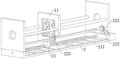
图1为本实用新型实施例所述的电缆剥切装置的整体结构示意图;Fig. 1 is a schematic diagram of the overall structure of the cable stripping and cutting device described in the embodiment of the present invention;
图2为本实用新型实施例所述的剥切机构的结构示意图;Fig. 2 is the structural representation of the peeling and cutting mechanism described in the utility model embodiment;
图3为本实用新型实施例所述的剥切机构的另一种可行的结构示意图;Fig. 3 is another feasible structural schematic diagram of the peeling and cutting mechanism described in the embodiment of the present invention;
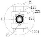
图4为本实用新型实施例所述的剥切机构和电缆之间的位置关系示意图;Fig. 4 is a schematic diagram of the positional relationship between the stripping mechanism and the cable described in the embodiment of the present invention;
图5为本实用新型实施例所述的固定板的结构示意图。Fig. 5 is a structural schematic diagram of the fixing plate described in the embodiment of the present invention.
附图标记说明:Explanation of reference signs:
11、盘刀架;121、基座;122、夹紧组件;1221、夹紧块;1222、滚轮;123、剥切刀;124、弹性储能部;125、导向组件;13、连接块;11. Disc cutter holder; 121. Base; 122. Clamping assembly; 1221. Clamping block; 1222. Roller; 123. Peeling and cutting knife; 124. Elastic energy storage part; 125. Guide assembly; 13. Connection block;
211、丝杠;221、转轴;222、第一齿轮组件;223、第二齿轮组件;211, lead screw; 221, rotating shaft; 222, first gear assembly; 223, second gear assembly;
3、底座;31、固定板;3. Base; 31. Fixed plate;
4、电缆。4. Cable.
具体实施方式detailed description
需要说明的是,在不冲突的情况下,本实用新型中的实施例及实施例中的特征可以相互组合。It should be noted that, in the case of no conflict, the embodiments of the present invention and the features in the embodiments can be combined with each other.
在本实用新型的描述中,需要说明的是,若出现“上”、“下”、“内”、“外”等指示方位或位置关系的术语,其为基于附图所示的方位或位置关系,仅是为了便于描述本实用新型和简化描述,而不是指示或暗示所指的装置或元件必须具有特定的方位、以特定的方位构造和操作,因此不能理解为对本实用新型的限制。此外,若出现“第一”、“第二”等术语,其也仅用于描述目的,而不能理解为指示或暗示相对重要性。In the description of the present utility model, it should be noted that if there are terms such as "up", "down", "inside" and "outside" that indicate orientation or positional relationship, it is based on the orientation or position shown in the drawings. The relationship is only for the convenience of describing the utility model and simplifying the description, but does not indicate or imply that the device or element referred to must have a specific orientation, be constructed and operated in a specific orientation, and thus should not be construed as a limitation of the utility model. In addition, if terms such as "first" and "second" appear, they are used for descriptive purposes only, and cannot be understood as indicating or implying relative importance.
此外,在本实用新型的描述中,除非另有明确的限定,术语“安装”、“相连”、“连接”“连接件”应做广义理解。例如,可以是固定连接,也可以是可拆卸连接,或一体地连接;可以是机械连接,也可以是电连接;可以是直接相连,也可以通过中间媒介间接相连,可以是两个元件内部的连通。对于本领域的普通技术人员而言,可以结合具体情况理解上述术语在本实用新型中的具体含义。In addition, in the description of the present utility model, unless otherwise clearly defined, the terms "installation", "connection", "connection" and "connector" should be interpreted broadly. For example, it can be a fixed connection, a detachable connection, or an integral connection; it can be a mechanical connection or an electrical connection; it can be a direct connection or an indirect connection through an intermediary; connected. Those of ordinary skill in the art can understand the specific meanings of the above terms in the present invention in combination with specific situations.
下面将参考附图并结合实施例来详细说明本实用新型。The utility model will be described in detail below with reference to the accompanying drawings and in conjunction with the embodiments.
本实施例涉及一种电缆剥切装置,其一种示例性的实施方式如图1并结合图2所示。整体而言,该电缆剥切装置主要包括底座3、剥切机构和驱动机构。通过驱动机构来驱使剥切机构在底座3上的滑动,同时利用剥切机构对电缆4进行剥切。This embodiment relates to a cable stripping and cutting device, an exemplary implementation thereof is shown in FIG. 1 and FIG. 2 in combination. Overall, the cable stripping and cutting device mainly includes a
基于上述的整体设计思想,在本实施例中,对于剥切机构来讲,为了方便其对电缆4进行螺旋切割,其具体包括滑动设置在底座3上的带有通孔的盘刀架11,以及转动设置在盘刀架11上的盘刀,盘刀能够夹紧穿设在通孔中的待剥切的电缆4,并切割电缆4。Based on the above-mentioned overall design idea, in this embodiment, for the stripping and cutting mechanism, in order to facilitate its spiral cutting of the
至于驱动机构,其包括设置在底座3上的驱动部,驱动部与盘刀架11通过第一传动部相连,且第一传动部与盘刀通过第二传动部相连;在驱动部的驱使下,第一传动部能够带动盘刀架11沿底座3长度方向往复滑移,并能够通过第二传动部带动盘刀绕通孔的轴向转动。优选的,驱动部可以为设置在底座上的驱动电机。As for the driving mechanism, it includes a driving part arranged on the
详细来讲,第一传动部包括转动设置在底座3上的与驱动部相连的丝杠211,丝杠211沿底座3长度方向布置,为了实现剥切机构对电缆4的螺旋剥切,在本实施例中,盘刀架11上设有带有螺纹孔的连接块13,连接块13与丝杠211螺纹连接。如此设置,随着驱动部驱使丝杠211的转动,与丝杠211丝扣连接的盘刀架11能够随着丝杠211的转动而沿着丝杠211的轴线方向来回移动。In detail, the first transmission part includes a
第二传动部包括转动设置在底座3上的与丝杠211平行布置的转轴221,设置在转轴221与丝杠211之间的第一齿轮组件222,以及设置在转轴221与盘刀之间的第二齿轮组件223。驱动部驱动丝杠211转动时,丝杠211能够通过第一齿轮组件222与第二齿轮组件223的传动,来驱使盘刀转动。对于盘刀架在盘刀架11上的转动来讲,盘刀通过连接轴承安装在盘刀架11上,并通过齿圈与第二齿轮组件223啮合连接。The second transmission part includes a
在具体实施时,上文中的第二齿轮组件223是沿自身轴线可转动地设置在盘刀的盘刀架11上的。并且,第二齿轮组件223与转轴221之间键连接,在转轴221上开设有能够使连接键滑动的滑槽。这样一来,随着盘刀沿着丝杠211轴线方向上的移动,转轴221始终能够为盘刀架中的旋转提供驱动力,从而便于盘刀以螺旋剥切的方式对电缆4进行切割。In a specific implementation, the above-mentioned
盘刀包括转动设置在盘刀架11上的圆盘状基座121,设置在基座121上的夹紧组件122,以及设置在基座121上的剥切刀123,且通孔贯通基座121设置,夹紧组件122用于弹性夹紧如图4所示的电缆4,剥切刀123用于切割电缆4,剥切刀123在基座121上的布置的方式,以及剥切刀123的结构形式,可参考图2和3。The disc cutter includes a disc-shaped
详细来讲,仍如图2所示,夹紧组件122具有相对布置在通孔内的两个夹紧块1221,各夹紧块1221均通过弹性储能部124与基座121相连,两个弹性储能部124释能时,能够驱动两个夹紧块1221相互靠近并弹性夹紧电缆4。两个夹紧块1221的相对侧上均转动设有用于抵紧电缆4的滚轮1222。弹性储能部124为弹簧,且弹簧的两端分别与夹紧块1221和基座121相连。剥切刀123为沿通孔径向相对布置的两个。In detail, as shown in FIG. 2 , the clamping
此外,仍如图3和图4所示,盘刀还包括设置在基座121上的导向组件125,导向组件125能够引导两个夹紧块1221沿通孔的径向移动。对于导向组件125来讲,其包括两个导向杆,导向杆可以是以完全穿经夹紧块1221的形式设置在基座121上的,也可以在导向杆远离与基座121联接的一端形成限位凸起,相应的,夹紧块1221上形成有如图……所示的两种内径不同的通孔,以防止两个夹紧块1221之间过于靠近,并改善贯通夹紧块1221的导向杆可能阻碍电缆4通过的问题。In addition, as still shown in FIG. 3 and FIG. 4 , the disc cutter further includes a
如上设置,滚轮1222在盘刀转动的过程中,能够抵紧电缆4,以固定电缆4的同时,还可沿着电缆4的周向进行转动,从而便于盘刀对电缆4进行螺旋剥切。在具体实施时,滚轮1222在夹紧块1221上安装时,其可以是以自身轴线的朝向可调的形式设置在夹紧块1221上,该种装配方式可以参考万向脚轮的装配方式,于此不做累述。As above, the
除上述可行的实施方式之外,在本实施例中,对于盘刀架11在基座121上的移动来讲,有一种可以作为备选的实施方式,详细来讲,盘刀架11的结构形式如图2所示,在盘刀架11的边沿部位,通过连接轴承连接设有能够沿自身轴线转动的齿轮,以及驱动该齿轮传动的电机。同时,该齿轮与盘刀的外齿圈相互啮合。至于电机,其也装配在盘刀架11上,并与外部电源电连接,需要进一步说明的是,该电机与外部电源相连接的电线,是通过拖链设置在底座3底部的。并且,该齿轮中间的开孔中设有内螺纹,并与上述实施方式中的丝杠211(此处的丝杠211固定安装在底座3上,自身不可转动)丝扣连接,这样一来,通过电机对该齿轮的驱动,在能够驱使盘刀转动的同时,也能够沿着丝杠211的轴向进行移动。In addition to the above-mentioned feasible implementation modes, in this embodiment, for the movement of the
针对于上述的各种实施方式,在基座121上,还设有如图5所示的对电缆4进行固定,以防止电缆4沿着自身的轴线方向移动的固定板31,该固定板31中也设有上文中的夹紧部,但固定板31是固定在底座3上的,并不随着电缆4的移动而移动。同时,在本实施例中,为增强底座3的结构强度,底座3上设有沿自身长度方向布置的至少一个导杆,优选为两个,盘刀架11滑动于导杆上,固定板31固装在导杆上。Regarding the above-mentioned various embodiments, on the
综上所述,本实施例的电缆剥切装置,通过设置的第一传动部和第二传动部,使盘刀在绕着通孔转动的同时,也能够沿着通孔的轴向进行移动,以使盘刀的运动路径呈现为螺旋线状,从而能够以螺旋剥切的方式对电缆4进行剥切。通过将连接块13与丝杠211之间的连接方式设置为螺纹连接,随着丝杠211的转动,连接块13能够带动盘刀架11沿着丝杠211的轴向来回移动。通过设置的第一齿轮组件222和第二齿轮组件223,驱动部能够驱动盘刀转动,从而便于对电缆4进行切割。通过在基座121上设置的夹紧组件122,能够夹紧待切割的电缆4,对电缆4加以固定,从而方便剥切刀123对电缆4进行切割。利用滚轮1222的转动,在对电缆4进行夹紧和固定的同时,也能够环绕电缆4进行旋转,从而方便剥切刀123对电缆4进行环切或者螺旋剥切。To sum up, the cable stripping and cutting device of this embodiment, through the first transmission part and the second transmission part, enables the disc cutter to move along the axial direction of the through hole while rotating around the through hole , so that the movement path of the disc cutter is helical, so that the
以上所述仅为本实用新型的较佳实施例而已,并不用以限制本实用新型,凡在本实用新型的精神和原则之内,所作的任何修改、等同替换、改进等,均应包含在本实用新型的保护范围之内。The above descriptions are only preferred embodiments of the present utility model, and are not intended to limit the present utility model. Any modifications, equivalent replacements, improvements, etc. made within the spirit and principles of the present utility model shall be included in the Within the protection scope of the present utility model.
Claims (10)
Translated fromChinesePriority Applications (1)
| Application Number | Priority Date | Filing Date | Title |
|---|---|---|---|
| CN202222621359.3UCN218335065U (en) | 2022-09-30 | 2022-09-30 | Cable stripping and cutting device |
Applications Claiming Priority (1)
| Application Number | Priority Date | Filing Date | Title |
|---|---|---|---|
| CN202222621359.3UCN218335065U (en) | 2022-09-30 | 2022-09-30 | Cable stripping and cutting device |
Publications (1)
| Publication Number | Publication Date |
|---|---|
| CN218335065Utrue CN218335065U (en) | 2023-01-17 |
Family
ID=84821550
Family Applications (1)
| Application Number | Title | Priority Date | Filing Date |
|---|---|---|---|
| CN202222621359.3UActiveCN218335065U (en) | 2022-09-30 | 2022-09-30 | Cable stripping and cutting device |
Country Status (1)
| Country | Link |
|---|---|
| CN (1) | CN218335065U (en) |
Cited By (1)
| Publication number | Priority date | Publication date | Assignee | Title |
|---|---|---|---|---|
| CN115566595A (en)* | 2022-09-30 | 2023-01-03 | 河北工业职业技术学院 | Cable Stripping and Cutting Device |
- 2022
- 2022-09-30CNCN202222621359.3Upatent/CN218335065U/enactiveActive
Cited By (1)
| Publication number | Priority date | Publication date | Assignee | Title |
|---|---|---|---|---|
| CN115566595A (en)* | 2022-09-30 | 2023-01-03 | 河北工业职业技术学院 | Cable Stripping and Cutting Device |
Similar Documents
| Publication | Publication Date | Title |
|---|---|---|
| CN115566595A (en) | Cable Stripping and Cutting Device | |
| CN113937672B (en) | Automatic stripping device for overhead cables | |
| CN218335065U (en) | Cable stripping and cutting device | |
| CN209786654U (en) | Cable stripper | |
| CN109888678A (en) | A cable insulation layer electric stripping combination device | |
| CN113794165B (en) | Handheld Overhead Cable Insulation Stripper | |
| CN117477452A (en) | Portable cable skinning electric tool | |
| CN114188892B (en) | Rotary cutting mechanism and cable stripping and cutting integrated machine | |
| CN119381099B (en) | Engineering-based cable processing technology | |
| CN114824994A (en) | Cable stripping method | |
| CN112636265B (en) | Cable separation stripping device | |
| CN216056057U (en) | Rotary type peeler is used to cable | |
| CN113922287B (en) | Rotary stripping machine for cables | |
| CN218525991U (en) | Novel cable processing equipment of skinning | |
| CN115149468B (en) | Cable wire stripping device for electric power engineering | |
| CN215897170U (en) | Automatic wire stripping device for overhead cable | |
| CN215897168U (en) | Electric peeling device | |
| CN113922290B (en) | Cable protective sleeve stripping device | |
| CN213936830U (en) | A cable auxiliary connection frame for electrical automation | |
| CN215897167U (en) | Hand-held type overhead cable insulating layer barker | |
| CN113794166B (en) | Electric peeling device | |
| CN115331897B (en) | Intelligent wire stripping device | |
| CN211182774U (en) | Cable stripper | |
| CN113363888A (en) | Cable stripping and cutting device | |
| CN113866886A (en) | Optical cable sheath stripping device |
Legal Events
| Date | Code | Title | Description |
|---|---|---|---|
| GR01 | Patent grant | ||
| GR01 | Patent grant | ||
| EE01 | Entry into force of recordation of patent licensing contract | ||
| EE01 | Entry into force of recordation of patent licensing contract | Assignee:Hebei Xiongan Tuo Micro Technology Co.,Ltd. Assignor:HEBEI College OF INDUSTRY AND TECHNOLOGY Contract record no.:X2024980000094 Denomination of utility model:Cable stripping and cutting device Granted publication date:20230117 License type:Common License Record date:20240103 | |
| TR01 | Transfer of patent right | ||
| TR01 | Transfer of patent right | Effective date of registration:20241119 Address after:No. 626 Hongqi Street, Qiaoxi District, Shijiazhuang City, Hebei Province, China 050093 Patentee after:Hebei Polytechnic University Country or region after:China Address before:050000 No. 626, Hongqi Street, Qiaoxi District, Shijiazhuang City, Hebei Province Patentee before:HEBEI College OF INDUSTRY AND TECHNOLOGY Country or region before:China |