CN218295388U - A multifunctional outdoor lighting device - Google Patents
A multifunctional outdoor lighting deviceDownload PDFInfo
- Publication number
- CN218295388U CN218295388UCN202222739621.4UCN202222739621UCN218295388UCN 218295388 UCN218295388 UCN 218295388UCN 202222739621 UCN202222739621 UCN 202222739621UCN 218295388 UCN218295388 UCN 218295388U
- Authority
- CN
- China
- Prior art keywords
- light
- bottom cover
- top cover
- wall
- transmitting tube
- Prior art date
- Legal status (The legal status is an assumption and is not a legal conclusion. Google has not performed a legal analysis and makes no representation as to the accuracy of the status listed.)
- Active
Links
- 238000007789sealingMethods0.000claimsabstractdescription23
- 230000005540biological transmissionEffects0.000claimsdescription14
- 238000003780insertionMethods0.000claimsdescription13
- 230000037431insertionEffects0.000claimsdescription13
- 229920001296polysiloxanePolymers0.000claimsdescription6
- 239000011324beadSubstances0.000claimsdescription4
- 239000000758substrateSubstances0.000claimsdescription4
- 230000008878couplingEffects0.000claims1
- 238000010168coupling processMethods0.000claims1
- 238000005859coupling reactionMethods0.000claims1
- 230000000694effectsEffects0.000abstractdescription3
- 230000002093peripheral effectEffects0.000description7
- 230000006835compressionEffects0.000description5
- 238000007906compressionMethods0.000description5
- 239000000428dustSubstances0.000description4
- XLYOFNOQVPJJNP-UHFFFAOYSA-NwaterChemical compoundOXLYOFNOQVPJJNP-UHFFFAOYSA-N0.000description4
- VYPSYNLAJGMNEJ-UHFFFAOYSA-NSilicium dioxideChemical compoundO=[Si]=OVYPSYNLAJGMNEJ-UHFFFAOYSA-N0.000description2
- 238000005516engineering processMethods0.000description2
- 238000000034methodMethods0.000description2
- 239000000741silica gelSubstances0.000description2
- 229910002027silica gelInorganic materials0.000description2
- 238000004078waterproofingMethods0.000description2
- 230000009286beneficial effectEffects0.000description1
- 238000007599dischargingMethods0.000description1
- 238000005286illuminationMethods0.000description1
- 239000003350keroseneSubstances0.000description1
- 239000002184metalSubstances0.000description1
- 230000001681protective effectEffects0.000description1
Images


Landscapes
- Non-Portable Lighting Devices Or Systems Thereof (AREA)
- Arrangement Of Elements, Cooling, Sealing, Or The Like Of Lighting Devices (AREA)
Abstract
Translated fromChinese
Description
Translated fromChinese技术领域technical field
本实用新型涉及户外照明领域,尤其涉及一种汽车前轮指向提示器。The utility model relates to the field of outdoor lighting, in particular to an automobile front wheel pointing indicator.
背景技术Background technique
户外露营是现在比较流行的一种度假方式,很多人还会在户外露营过夜,过夜露营的话,户外照明装置是必不可少的。Outdoor camping is a popular way of vacation now, and many people will spend the night camping outdoors. For overnight camping, outdoor lighting is essential.
现有的户外照明装置大致有汽灯、煤油灯、蜡烛灯和LED灯这几类,相比其他几类,LED灯是现代露营常用的露营灯。中国专利公开号CN210141494U公开了一种多功能露营灯,该专利文献中记载了其包括:呈长条状的壳体,壳体两侧端部上均设置有安装凹槽,安装凹槽嵌合连接有磁铁,壳体内设置有LED灯管、蓄电池和控制电路;壳体一侧端部内设置有电筒且另一侧端部上设置有防水盖,防水盖的端面上设置有控制按钮,防水端盖内设置有连接到蓄电池的充电口和放电口。该专利文献宣称相比于传统技术,具有防水防尘作用,灯光的照射范围较大,但实际市面上依照此技术方案所生产的露营灯,壳体内设置的发光源,实际产品要么是只能朝向一个方向照射出光线的单面灯板,要么是能向两个相反方向照射出光线的双面灯板,上述这两种发光源的方式都是市面上常见的露营灯构成结构,但都有一个共同的问题,就是如果需要让光线能散射到四周,就只能在壳体内增加弧形的反射部件配合,这样一来,壳体内除了电池就无法再容置下其他零部件。这样总会有一个方向是无法照射出光线的,也就无法实现360度的大范围照明目的。除此之外,此类露营灯还有的是在壳体内设置一个棒状灯管来实现向四周发光。这类发光方式的露营灯以及前面所提到的两种发光方式的露营灯,为了在户外能够实现防水防尘作用,露营灯壳体的两端都会设置防水的密封结构,但由于壳体内已经无法容纳其他部件,两端用来防水的端盖只能依靠扣合的方式盖在壳体两端,然后在端盖和壳体的结合处再套设一个稍宽的胶圈来将结合处覆盖包裹,以达到防水的目的。众所周知,户外露营,由于环境复杂,所使用的物品很容易会出现跌落磕碰等现象。经过众多使用者反馈,我们发现仅仅靠端盖过盈配合的扣在壳体两端,是很容易在摔落磕碰的情况下,让端盖松脱或掉落,导致露营灯的防水和防尘功能失效,产品极易损坏。Existing outdoor lighting devices generally include gas lamps, kerosene lamps, candle lamps and LED lamps. Compared with other types, LED lamps are commonly used camping lamps for modern camping. Chinese Patent Publication No. CN210141494U discloses a multi-functional camping lamp, which is recorded in the patent document as comprising: a strip-shaped shell, and mounting grooves are arranged on the ends of both sides of the shell, and the mounting grooves fit Connected with a magnet, the housing is provided with an LED light tube, a battery and a control circuit; a flashlight is provided at one end of the housing and a waterproof cover is provided at the other end, and a control button is provided on the end surface of the waterproof cover. The cover is provided with a charging port and a discharging port connected to the storage battery. This patent document claims that compared with the traditional technology, it has the function of waterproof and dustproof, and the illumination range of the light is larger. However, the camping light produced according to this technical solution on the market actually has a light source installed in the housing. The actual product either can only A single-sided light panel that radiates light in one direction, or a double-sided light panel that can radiate light in two opposite directions. There is a common problem, that is, if you need to scatter light around, you can only add arc-shaped reflective parts in the casing, so that other components except the battery cannot be accommodated in the casing. In this way, there will always be a direction where light cannot be irradiated, and the purpose of 360-degree large-scale lighting cannot be achieved. In addition, this kind of camping lamp also has a rod-shaped lamp tube arranged in the housing to realize the light emitting around. In order to achieve waterproof and dustproof effect outdoors for this kind of camping light with light-emitting mode and the camping light with two light-emitting modes mentioned above, both ends of the camping light shell will be provided with waterproof sealing structure, but because the shell has already Unable to accommodate other parts, the end caps used for waterproofing at both ends can only be covered on both ends of the shell by snap-fitting, and then a slightly wider rubber ring is set at the joint between the end cap and the shell to seal the joint Cover the package for waterproofing. As we all know, outdoor camping, due to the complex environment, the items used are prone to falling and bumping. After feedback from many users, we found that only relying on the interference fit of the end cap to buckle the two ends of the shell, it is easy to make the end cap loose or fall off when it is dropped and bumped, resulting in the waterproof and waterproof of the camping light. The dust function fails, and the product is easily damaged.
因此现有的这类多功能户外露营灯类型的照明装置需要进一步的改进。Therefore, the existing lighting device of this type of multifunctional outdoor camping lamp needs further improvement.
实用新型内容Utility model content
本实用新型的目的是为了提供一种防水性能好、能360度发光、且兼具手电功能多功能户外照明装置。The purpose of the utility model is to provide a multifunctional outdoor lighting device with good waterproof performance, 360-degree light emission and flashlight function.
为了达到上述目的,本实用新型采用以下方案:一种多功能户外照明装置,包括有棒状发光部,所述棒状发光部的一端设有底盖,底盖上具有一投射灯,所述棒状发光部的另一端设有顶盖,棒状发光部内容置有电池和能向环境四周发光的环绕光源,顶盖上具有能为电池充电的充电插口和控制投射灯以及环绕光源工作的控制开关,所述棒状发光部包括有两端开口的透光管,在该透光管内设有承载支架,承载支架中央沿轴线具有贯通孔,所述电池容置在贯通孔内,所述环绕光源沿所述承载支架的外壁设置,所述底盖和顶盖分别封堵在透光管两端的开口上,所述承载支架的两端分别与对应的所述底盖和顶盖相邻的一侧连接固定,在所述底盖和顶盖分别与透光管端部的结合处分别设有密封圈。In order to achieve the above purpose, the utility model adopts the following scheme: a multi-functional outdoor lighting device, including a rod-shaped light-emitting part, one end of the rod-shaped light-emitting part is provided with a bottom cover, and a projection lamp is provided on the bottom cover, and the rod-shaped light-emitting part The other end of the part is provided with a top cover, and the rod-shaped light-emitting part is equipped with a battery and a surrounding light source that can emit light around the environment. The top cover has a charging socket for charging the battery and a control switch for controlling the projection lamp and the surrounding light source. The rod-shaped light-emitting part includes a light-transmitting tube with openings at both ends, and a bearing bracket is arranged in the light-transmitting tube. The center of the bearing bracket has a through hole along the axis. The battery is accommodated in the through hole. The outer wall of the bearing bracket is set, the bottom cover and the top cover are respectively blocked on the openings at both ends of the light-transmitting tube, and the two ends of the bearing bracket are respectively connected and fixed to the corresponding adjacent sides of the bottom cover and the top cover , sealing rings are respectively provided at the joints of the bottom cover and the top cover and the ends of the light-transmitting tube respectively.
作为本实用新型进一步地方案,所述底盖包括有外轮廓与所述透光管外壁轮廓相同的底盖基座,底盖基座朝向透光管开口的一侧具有内凹的底盖空腔,所述投射灯容置在底盖空腔内,在所述底盖空腔的底面贯穿有能容投射灯光线照射出的投光口,所述底盖基座朝向相邻透光管开口的一侧、向外延伸有能插接在该侧透光管开口内的第一插接部,第一插接部的外壁与透光管的内壁相贴合,位于底盖与透光管端部结合处的密封圈套设在第一插接部外壁上,与所述底盖基座对应的所述承载支架一端连接在所述底盖空腔中。As a further solution of the utility model, the bottom cover includes a bottom cover base whose outer contour is the same as that of the outer wall of the light-transmitting tube, and the side of the bottom cover base facing the opening of the light-transmitting tube has a concave bottom cover cavity cavity, the projection lamp is accommodated in the cavity of the bottom cover, and the bottom surface of the cavity of the bottom cover is penetrated with a light projection port capable of accommodating the light of the projection lamp, and the base of the bottom cover faces the adjacent light-transmitting tube On one side of the opening, there is a first insertion part that can be plugged into the opening of the light-transmitting tube on the side. The sealing ring at the junction of the pipe ends is sleeved on the outer wall of the first socket part, and one end of the bearing bracket corresponding to the base of the bottom cover is connected in the cavity of the bottom cover.
作为本实用新型进一步地方案,所述顶盖包括有外轮廓与所述透光管外壁轮廓相同的顶盖基座,在顶盖基座朝向透光管开口的一侧具有内凹的顶盖空腔,在所述顶盖空腔的顶部壁面上分别贯穿有多个能容所述充电插口和控制开关穿过的固定孔,在所述顶盖基座朝向相邻透光管开口的一侧、向外延伸有能插接在该侧透光管开口内的第二插接部,位于顶盖与透光管端部结合处的密封圈套设在第二插接部外壁上,与所述顶盖基座对应的所述承载支架一端连接在所述顶盖空腔中。As a further solution of the present invention, the top cover includes a top cover base whose outer contour is the same as that of the outer wall of the light-transmitting tube, and a concave top cover is provided on the side of the top-cover base facing the opening of the light-transmitting tube A cavity, on the top wall of the top cover cavity, a plurality of fixing holes that can accommodate the charging socket and the control switch pass through, and on the top cover base facing the opening of the adjacent light-transmitting tube There is a second insertion part that can be inserted into the opening of the light transmission tube on the side and outwards, and the sealing ring located at the junction of the top cover and the end of the light transmission tube is sleeved on the outer wall of the second insertion part, and the One end of the bearing bracket corresponding to the top cover base is connected in the top cover cavity.
作为本实用新型优选地方案,所述透光管和所述承载支架分别呈三角形的管状体,所述透光管的三个夹角处呈圆弧形,,所述透光管内壁垂直间隔排布有波纹齿,在所述承载支架上下两端位于三个夹角处分别设有螺丝连接孔,在所述顶盖空腔和底盖空腔内分别贯穿设有与所述螺丝连接孔相匹配的螺丝穿孔,所述顶盖与所述底盖分别通过在相对应的螺丝连接孔和螺丝穿孔内拧入螺丝与所述承载支架端部相连接,所述环绕光源分别设置在承载支架的三面外壁上。As a preferred solution of the present utility model, the light-transmitting tube and the bearing bracket are respectively triangular tubular bodies, the three included angles of the light-transmitting tube are arc-shaped, and the inner walls of the light-transmitting tube are vertically spaced Arranged with corrugated teeth, the upper and lower ends of the bearing bracket are respectively provided with screw connection holes at three angles, and the top cover cavity and the bottom cover cavity are respectively provided with screw connection holes. Matching screw holes, the top cover and the bottom cover are respectively screwed into the corresponding screw connection holes and screw holes to connect with the end of the bearing bracket, and the surrounding light sources are respectively arranged on the bearing bracket on the three outer walls.
作为本实用新型优选地方案,在所述承载支架的三面外壁上分别各自设有相对称的插槽,所述环绕光源包括有能插入所述插槽内的基板,以及设置在基板上的LED灯珠。As a preferred solution of the present invention, symmetrical slots are respectively provided on the three outer walls of the supporting bracket, the surrounding light source includes a substrate that can be inserted into the slot, and LEDs arranged on the substrate Lamp beads.
作为本实用新型优选地方案,所述控制开关包括有一端插在所述顶盖空腔内、另一端伸入所述贯通孔内的控制电路板,在控制电路板上设有顶部能穿过固定孔的开关按钮,所述充电插口远离固定孔的一端连接固定在控制电路板上。As a preferred solution of the present invention, the control switch includes a control circuit board with one end inserted into the cavity of the top cover and the other end extending into the through hole. The switch button of the fixing hole, the end of the charging socket away from the fixing hole is connected and fixed on the control circuit board.
作为本实用新型优选地方案,所述底盖基座的底部一侧向下延伸有与所述投光口同轴心的第一环形凸台,环绕所述第一环形凸台的圆周外壁设有外螺纹,在所述第一环形凸台的底部设有透光板,在位于所述底盖基座一端设有能扣合、并包裹在透光管一端外壁上的底盖外壳,所述底盖外壳的一侧贯穿有能容所述第一环形凸台穿过的第一套孔,所述底盖外壳包裹透光管的壁面遮盖在所在的密封圈上,在所述第一环形凸台外通过螺纹连接套设有能压在所述底盖外壳上的第一锁紧环。As a preferred solution of the present invention, the bottom side of the base of the bottom cover extends downwards with a first annular boss coaxial with the light projecting port, and a peripheral outer wall around the first annular boss is provided. There are external threads, a light-transmitting plate is provided at the bottom of the first annular boss, and a bottom cover shell that can be buckled and wrapped on the outer wall of one end of the light-transmitting tube is provided at one end of the base of the bottom cover. One side of the bottom cover shell runs through a first set of holes that can accommodate the first annular boss to pass through, and the wall surface of the bottom cover shell that wraps the light-transmitting tube is covered on the sealing ring where it is located. A first locking ring that can be pressed on the bottom cover shell is provided on the outside of the annular boss through a threaded connection sleeve.
作为本实用新型优选地方案,所述顶盖基座的顶部向上延伸有第二环形凸台,环绕第二环形凸台的圆周外壁设有外螺纹,在位于所述顶盖基座一端设有能扣合、并包裹在对应透光管一端外壁上的顶盖外壳,在所述顶盖外壳的顶部壁面贯穿有能容第二环形凸台穿过的第二套孔,在所述第二环形凸台的圆周外壁上通过螺纹连接套设有能压在顶盖外壳上的第二锁紧环,所述顶盖外壳包裹透光管的壁面遮盖在所在的密封圈上。As a preferred solution of the present invention, the top of the top cover base extends upwards with a second annular boss, and the outer wall surrounding the second annular boss is provided with external threads, and one end of the top cover base is provided with A top cover shell that can be fastened and wrapped on the outer wall of one end of the corresponding light-transmitting tube. A second set of holes that can accommodate the second annular boss passes through the top wall of the top cover shell. The outer peripheral wall of the annular boss is provided with a second locking ring that can be pressed on the top cover shell through a threaded connection sleeve, and the top cover shell wraps the wall surface of the light-transmitting tube and covers the sealing ring there.
作为本实用新型优选地方案,在所述第二环形凸台的顶面设有硅胶盖,在位于所述第二锁紧环上方的第二环形凸台的圆周外壁上通过螺纹连接套设有压紧套,该压紧套将硅胶盖压在所述第二环形凸台的顶面上。As a preferred solution of the present utility model, a silicone cover is provided on the top surface of the second annular boss, and a cover is provided on the peripheral outer wall of the second annular boss above the second locking ring through a threaded connection sleeve. A compression sleeve, the compression sleeve presses the silicone cover on the top surface of the second annular boss.
作为本实用新型优选地方案,所述顶盖外壳和所述底盖外壳的外壁上设有磁铁。As a preferred solution of the present invention, magnets are provided on the outer walls of the top cover shell and the bottom cover shell.
综上所述,本实用新型相对于现有技术其有益效果是:本实用新型通过在透光管内设置一个呈三角形管状体的承载支架,将LED发光板分别插接固定在承载支架的三个面上,利用承载支架将透光管两端的底盖和顶盖用螺丝锁紧的方案,能达到即使遇到摔落磕碰,底盖和顶盖也不会松脱掉落的效果。另外,配合底盖和顶盖分别与透光管端部的结合处分别设置的密封圈,能有效保障防水防尘的功能。透光管内内壁垂直间隔排布的波纹齿配合三面发光的环绕光源能达到360度大范围照射的目的,不会出现总有一方无法照射发光的问题。此外,底盖上具有的投射灯能在需要聚光照明的时候,充当手电使用。结构简单,产品牢固。In summary, compared with the prior art, the beneficial effects of the present utility model are as follows: the utility model sets a triangular tubular bearing bracket in the light-transmitting tube, and inserts and fixes the LED light-emitting panels on the three bearing brackets respectively. On the surface, the bottom cover and the top cover at both ends of the light-transmitting tube are locked with screws by using the supporting bracket, so that even if the bottom cover and the top cover are dropped and bumped, the bottom cover and the top cover will not loosen and fall off. In addition, the joints of the bottom cover and the top cover and the end of the light-transmitting tube are respectively provided with sealing rings, which can effectively guarantee the waterproof and dustproof function. The corrugated teeth arranged at vertical intervals on the inner wall of the light-transmitting tube and the surrounding light source that emits light from three sides can achieve the purpose of 360-degree wide-range irradiation, and there will be no problem that one side cannot be illuminated to emit light. In addition, the projection lamp on the bottom cover can be used as a flashlight when spot lighting is required. The structure is simple and the product is firm.
附图说明Description of drawings
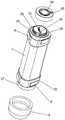
图1为本实用新型的立体视图。Fig. 1 is a perspective view of the utility model.
图2为本实用新型的局部分解视图之一。Fig. 2 is one of partial exploded views of the utility model.
图3为本实用新型的局部分解视图之二。Fig. 3 is the second partial exploded view of the utility model.
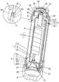
图4为本实用新型的纵向剖面视图之一。Fig. 4 is one of the longitudinal sectional views of the utility model.
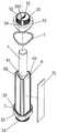
图5为本实用新型的整体分解视图。Fig. 5 is an overall exploded view of the utility model.
图6为本实用新型的局部零件分解视图。Fig. 6 is an exploded view of some parts of the utility model.
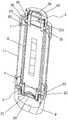
图7为本实用新型的纵向剖面视图之二。Fig. 7 is the second longitudinal sectional view of the utility model.
图8为本实用新型的横向剖面视图。Fig. 8 is a transverse sectional view of the utility model.
附图标记说明:1、棒状发光部;2、底盖;3、顶盖;4、电池;5、环绕光源;6、承载支架;7、密封圈;8、磁铁;9、保护头;10、螺丝穿孔;11、透光管;20、透光板;21、投射灯;22、底盖基座;23、第一插接部;24、第一环形凸台;25、底盖外壳;26、第一套孔;27、第一锁紧环;30、控制电路板;31、充电插口;32、控制开关;33、顶盖基座;34、第二插接部;35、第二环形凸台;36、顶盖外壳;37、第二套孔;38、第二锁紧环;39、硅胶盖;40、压紧套;51、基板;61、贯通孔;62、螺丝连接孔;63、插槽;221、底盖空腔;222、投光口;331、顶盖空腔;332、固定孔。Explanation of reference signs: 1. Rod-shaped light-emitting part; 2. Bottom cover; 3. Top cover; 4. Battery; 5. Surrounding light source; 6. Bearing bracket; 7. Sealing ring; 8. Magnet; , screw perforation; 11, light-transmitting tube; 20, light-transmitting plate; 21, projection lamp; 22, bottom cover base; 23, first socket part; 24, first annular boss; 26. The first set of holes; 27. The first locking ring; 30. The control circuit board; 31. The charging socket; 32. The control switch; 33. The top cover base; 34. The second socket part; 35. The second Annular boss; 36, top cover shell; 37, second set of holes; 38, second locking ring; 39, silica gel cover; 40, compression sleeve; 51, base plate; 61, through hole; 62, screw connection hole ; 63, slot; 221, bottom cover cavity; 222, light projection port; 331, top cover cavity; 332, fixing hole.
具体实施方式detailed description
以下具体实施内容提供用于实施本实用新型的多种不同实施例或实例。当然,这些仅为实施例或实例且不希望具限制性。另外,在不同实施例中可能使用重复标号标示,如重复的数字及/或字母。这些重复是为了简单清楚的描述本发明,不代表所讨论的不同实施例及/或结构之间有特定的关系。The following specific implementation content provides a variety of different embodiments or examples for implementing the utility model. Of course, these are merely embodiments or examples and are not intended to be limiting. In addition, repeated reference numerals, such as repeated numbers and/or letters, may be used in different embodiments. These repetitions are for the purpose of simply and clearly describing the present invention, and do not represent any specific relationship between the different embodiments and/or structures discussed.
此外,其中可能用到与空间相关的用词,像是“在…下方”、“下侧”、“由内而外”、“上方”、“上侧”及类似的用词,这些关系词为了便于描述附图中一个些元件或特征与另一个些元件或特征之间的关系,这些空间关系词包括使用中或操作中的装置之不同方位,以及附图中所描述的方位。装置可能被转向不同方位旋转90度或其他方位,则其中使用的空间相关形容词也可相同地照着解释,因此不能理解为对本发明的限制,术语“第一”、“第二”仅用于描述目的,而不能理解为指示或暗示相对重要性或者隐含指明所指示的技术特征的数量。由此,限定有“第一”、“第二”的特征可以明示或者隐含地包括一个或者更多个该特征。In addition, terms related to space may be used, such as "below", "underside", "inside out", "above", "upper side" and similar terms, these relative words To facilitate describing the relationship between one element or feature and another element or feature in the drawings, these spatial relative terms include different orientations of the device in use or operation, as well as the orientation depicted in the drawings. The device may be turned to different orientations and rotated 90 degrees or other orientations, and the space-related adjectives used therein can also be interpreted in the same way, so it cannot be construed as limiting the present invention, and the terms "first" and "second" are only used for Descriptive purposes, and should not be understood as indicating or implying relative importance or implying the number of technical features indicated. Thus, a feature defined as "first" and "second" may explicitly or implicitly include one or more of these features.
下面结合附图说明和具体实施方式对本实用新型作进一步描述:如图1至图4所示的一种多功能户外照明装置,包括有棒状发光部1,所述棒状发光部1的一端设有底盖2,底盖2上具有一投射灯21,所述棒状发光部1的另一端设有顶盖3,棒状发光部1内容置有电池4和能向环境四周发光的环绕光源5,顶盖3上具有能为电池4充电的充电插口31和控制投射灯21以及环绕光源5工作的控制开关32,所述棒状发光部1包括有两端开口、内壁垂直间隔排布有波纹齿(图中未示出)的透光管11,所述透光管11呈三角形的管状体,透光管11三个夹角处呈圆弧形,在该透光管11内设有同样呈三角形管状体的承载支架6,承载支架6中央沿轴线具有贯通孔61,本实施例中贯通孔61也呈三角形,这样电池4能被牢牢夹持在贯通孔61内。所述环绕光源5沿所述承载支架6的外壁设置,所述底盖2和顶盖3分别封堵在透光管11两端的开口上,所述承载支架6的两端分别与对应的所述底盖2和顶盖3相邻的一侧连接固定,在所述底盖2和顶盖3分别与透光管11端部的结合处分别设有密封圈7。 利用承载支架将透光管两端的底盖和顶盖连接,相比现有的仅仅插接的方式,更加稳固,防止摔落磕碰后底盖和顶盖松脱,进而导致防水失效。The utility model will be further described below in conjunction with the accompanying drawings and specific embodiments: a multifunctional outdoor lighting device as shown in Figures 1 to 4 includes a rod-shaped light-emitting part 1, and one end of the rod-shaped light-emitting part 1 is provided with The
其中,如图4至图6所示,所述底盖2包括有外轮廓与所述透光管11外壁轮廓相同的底盖基座22,也就是说本实施例中底盖基座22的外形也与透光管11外形相同,当然底盖基座22的外形也可以不与透光管11外形相同,底盖基座22朝向透光管11开口的一侧具有内凹的底盖空腔221,所述投射灯21容置在底盖空腔221内,在所述底盖空腔221的底面贯穿有能容投射灯21光线照射出的投光口222,所述底盖基座22朝向相邻透光管11开口的一侧、向外延伸有能插接在该侧透光管11开口内的第一插接部23,第一插接部23的外壁与透光管11的内壁相贴合,位于底盖2与透光管11端部结合处的密封圈7环绕套设在第一插接部23外壁上,如图4中所示,在本实施例中,第一插接部23的圆周外壁直径是小于底盖基座22本身的外周外壁直径的,这样一来,密封圈7环绕套设在第一插接部23外壁上后,密封圈7的左右两侧壁就分别与相邻的透光管11端部边缘以及与底盖基座22与第一插接部23结合的边缘抵接在一起,与所述底盖基座22对应的所述承载支架6一端连接在所述底盖空腔221中。所述顶盖3包括有外轮廓与所述透光管11外壁轮廓相同的顶盖基座33,在顶盖基座33朝向透光管11开口的一侧具有向上内凹的顶盖空腔331,在所述顶盖空腔331的顶部壁面上分别贯穿有多个能容所述充电插口31和控制开关32穿过的固定孔332,在所述顶盖基座33朝向相邻透光管11开口的一侧、向外延伸有能插接在该侧透光管11开口内的第二插接部34,位于顶盖3与透光管11端部结合处的密封圈7套设在第二插接部34外壁上,需要说明的是第二插接部34与第一插接部23的构造外形均为相同的,并且密封圈7套设在第二插接部34外壁上后,也与密封圈7环绕套设在第一插接部23上的结构以及效果相同,与所述顶盖基座33对应的所述承载支架6一端连接在所述顶盖空腔331中。Wherein, as shown in FIG. 4 to FIG. 6, the
另外,如图5至图8所示,在所述承载支架6上下两端位于三个夹角处分别设有螺丝连接孔62,在所述顶盖空腔331和底盖空腔221内分别贯穿设有与所述螺丝连接孔62相匹配的螺丝穿孔10,所述顶盖3与所述底盖2分别通过在相对应的螺丝连接孔62和螺丝穿孔10内拧入螺丝与所述承载支架6端部相连接。其中所述环绕光源5分别设置在承载支架6的三面外壁上,具体而言:在所述承载支架6的三面外壁上分别各自设有相对称的插槽63,所述环绕光源5包括有能插入所述插槽63内的基板51,以及设置在基板51上的LED灯珠(图中未示出)。LED灯珠照射的光线会直接透过透光管11壁面射出,光线首先会经过透光管11内壁垂直间隔排布有波纹齿(图中未示出)反复折射后再从透光管11外壁投射出,这样呈三角形管状体的透光管11就能均匀的照出,不会形成光斑,也不会出现光线死角。In addition, as shown in FIGS. 5 to 8 , screw connection holes 62 are respectively provided at three angles at the upper and lower ends of the
本实施例中,所述控制开关32包括有一端插在所述顶盖空腔331内、另一端伸入所述贯通孔61内的控制电路板30,在控制电路板30上设有顶部能穿过固定孔332的开关按钮,所述充电插口31远离固定孔332的一端连接固定在控制电路板30上。通过开关按钮能够控制投射灯21以及环绕光源5的发光和熄灭,也能通过内置程序,让投射灯21以及环绕光源5产生闪烁等动作,在野外可作为救援信号用。In this embodiment, the
为了能够防水防尘功能更进一步的得到保障,所述底盖基座22的底部一侧向下延伸有与所述投光口222同轴心的第一环形凸台24,环绕所述第一环形凸台24的圆周外壁设有外螺纹,在所述第一环形凸台24的底部设有透光板20,在位于所述底盖基座22一端设有能扣合、并包裹在透光管11一端外壁上的底盖外壳25,所述底盖外壳25的一侧贯穿有能容所述第一环形凸台24穿过的第一套孔26,所述底盖外壳25包裹透光管11的壁面遮盖在所在的密封圈7上,在所述第一环形凸台24外通过螺纹连接套设有能压在所述底盖外壳25上的第一锁紧环27。所述顶盖基座33的顶部向上延伸有第二环形凸台35,环绕第二环形凸台35的圆周外壁设有外螺纹,在位于所述顶盖基座33一端设有能扣合、并包裹在对应透光管11一端外壁上的顶盖外壳36,在所述顶盖外壳36的顶部壁面贯穿有能容第二环形凸台35穿过的第二套孔37,在所述第二环形凸台35的圆周外壁上通过螺纹连接套设有能压在顶盖外壳36上的第二锁紧环38,所述顶盖外壳36包裹透光管11的壁面遮盖在所在的密封圈7上。在所述第二环形凸台35的顶面设有硅胶盖39,在位于所述第二锁紧环38上方的第二环形凸台35的圆周外壁上通过螺纹连接套设有压紧套40,该压紧套40将硅胶盖39压在所述第二环形凸台35的顶面上。如图4中所示,底盖外壳25包裹透光管11的壁面遮盖在所在的密封圈7上能配合密封圈7进一步的防止水汽或灰尘进入底盖2内,而所述顶盖外壳36包裹透光管11的壁面遮盖在所在的密封圈7上,能进一步的防止水汽或灰尘进入顶盖3内,硅胶盖39则扣合在第二环形凸台35的顶面,在能顺利按压固定孔332内的开关按钮之外,也能防止水汽灰尘从第二环形凸台35的顶面的固定孔332进入顶盖基座33内。In order to further ensure the waterproof and dustproof function, the bottom side of the
本实施例中还在第一锁紧环27外套设有保护头9,这样能进一步防止水汽从第一环形凸台24中央的孔进入底盖基座22或投射灯21内,投射灯21是现有的技术,结构为:具有一个灯杯,灯杯一端是发光芯片,灯杯的另一端则罩设在投光口222上,透光板20则在第一环形凸台24上,由第一锁紧环27压着。In this embodiment, the
需要说明的是第一环形凸台24中央是投光口222,而第二环形凸台35的顶部中央则是遮盖封闭的,固定孔332就贯穿在遮盖封闭的第二环形凸台35的顶部,所述顶盖外壳36和所述底盖外壳25的外壁上设有磁铁8,磁体8让整个多功能户外照明装置吸附在金属上。It should be noted that the center of the first
以上显示和描述了本实用新型的基本原理和主要特征以及本实用新型的优点,本行业的技术人员应该了解,本实用新型不受上述实施例的限制,上述实施例和说明书中描述的只是说明本实用新型的原理,在不脱离本实用新型精神和范围的前提下,本实用新型还会有各种变化和改进,这些变化和改进都落入要求保护的本实用新型范围内。本实用新型要求保护范围由所附的权利要求书及其等效物界定。The basic principles and main features of the present utility model and the advantages of the present utility model have been shown and described above. Those skilled in the art should understand that the present utility model is not limited by the above-mentioned embodiments. What are described in the above-mentioned embodiments and description are only illustrations The principle of the utility model, under the premise of not departing from the spirit and scope of the utility model, the utility model also has various changes and improvements, and these changes and improvements all fall within the scope of the claimed utility model. The scope of protection required by the utility model is defined by the appended claims and their equivalents.
Claims (10)
Priority Applications (1)
| Application Number | Priority Date | Filing Date | Title |
|---|---|---|---|
| CN202222739621.4UCN218295388U (en) | 2022-10-18 | 2022-10-18 | A multifunctional outdoor lighting device |
Applications Claiming Priority (1)
| Application Number | Priority Date | Filing Date | Title |
|---|---|---|---|
| CN202222739621.4UCN218295388U (en) | 2022-10-18 | 2022-10-18 | A multifunctional outdoor lighting device |
Publications (1)
| Publication Number | Publication Date |
|---|---|
| CN218295388Utrue CN218295388U (en) | 2023-01-13 |
Family
ID=84808632
Family Applications (1)
| Application Number | Title | Priority Date | Filing Date |
|---|---|---|---|
| CN202222739621.4UActiveCN218295388U (en) | 2022-10-18 | 2022-10-18 | A multifunctional outdoor lighting device |
Country Status (1)
| Country | Link |
|---|---|
| CN (1) | CN218295388U (en) |
- 2022
- 2022-10-18CNCN202222739621.4Upatent/CN218295388U/enactiveActive
Similar Documents
| Publication | Publication Date | Title |
|---|---|---|
| CN107690555B (en) | Lamp holder rotating assembly and lighting device | |
| JP2007214096A (en) | Lighting fixture | |
| CN107690553B (en) | Lighting lamp holder | |
| CN107690554B (en) | Lamp post and lighting device | |
| TW201339502A (en) | A light fixture | |
| CN218295388U (en) | A multifunctional outdoor lighting device | |
| WO1998014733A1 (en) | Light bulb device | |
| CN207661539U (en) | a lighting fixture | |
| US6203178B1 (en) | Lighting apparatus | |
| TW201315940A (en) | Candle lamp | |
| JP3162972U (en) | Light guide structure of lamp | |
| CN207584411U (en) | Lamps and lanterns | |
| CN205782126U (en) | A kind of modified form LED | |
| CN102135257A (en) | Nodal lamps | |
| CN210624339U (en) | Garage lamp | |
| CN111412407A (en) | Lamp and light source module thereof | |
| CN209819465U (en) | Novel projection lamp | |
| WO2016015506A1 (en) | Led lamp | |
| US20050078470A1 (en) | Megaphone | |
| JP2976217B2 (en) | Lighting equipment | |
| JP2006221939A (en) | lighting equipment | |
| CN206637357U (en) | A multifunctional search headlight | |
| CN214948333U (en) | Handheld lamps | |
| CN110736052A (en) | a garage light | |
| CN216769142U (en) | Lamp holder and desk lamp with same |
Legal Events
| Date | Code | Title | Description |
|---|---|---|---|
| GR01 | Patent grant | ||
| GR01 | Patent grant |