CN218178456U - Rotary module and camera module - Google Patents
Rotary module and camera moduleDownload PDFInfo
- Publication number
- CN218178456U CN218178456UCN202222393163.3UCN202222393163UCN218178456UCN 218178456 UCN218178456 UCN 218178456UCN 202222393163 UCN202222393163 UCN 202222393163UCN 218178456 UCN218178456 UCN 218178456U
- Authority
- CN
- China
- Prior art keywords
- annular
- rotating shaft
- rotary module
- cages
- abutting portion
- Prior art date
- Legal status (The legal status is an assumption and is not a legal conclusion. Google has not performed a legal analysis and makes no representation as to the accuracy of the status listed.)
- Active
Links
- 238000005096rolling processMethods0.000claimsabstractdescription51
- 230000000712assemblyEffects0.000claimsabstractdescription4
- 238000000429assemblyMethods0.000claimsabstractdescription4
- 238000009434installationMethods0.000claimsdescription37
- 230000000670limiting effectEffects0.000claimsdescription14
- 230000002093peripheral effectEffects0.000claimsdescription8
- 230000007423decreaseEffects0.000claimsdescription3
- 230000003247decreasing effectEffects0.000abstract1
- 238000010586diagramMethods0.000description3
- 238000000034methodMethods0.000description3
- 238000003384imaging methodMethods0.000description2
- 230000009286beneficial effectEffects0.000description1
- 230000008094contradictory effectEffects0.000description1
- 230000005484gravityEffects0.000description1
- 230000036961partial effectEffects0.000description1
- 230000002829reductive effectEffects0.000description1
- 230000002441reversible effectEffects0.000description1
- 230000009466transformationEffects0.000description1
Images


Landscapes
- Accessories Of Cameras (AREA)
Abstract
Description
Translated fromChinese技术领域technical field
本实用新型涉及摄影器材技术领域,特别涉及一种旋转模组和摄影组件。The utility model relates to the technical field of photographic equipment, in particular to a rotary module and a photographic assembly.
背景技术Background technique
随着生活水平的提高,摄影逐渐成为越来越多人的业余爱好。在手持拍摄、稳定器拍摄、肩抗拍摄以及三脚架拍摄过程中,为了方便拍摄,往往需要装配摄影配件完成手动旋转拍摄,如魔术转接头、快拆板、手柄、三脚架和上手提等,手柄和上手提可以用来调节不同角度的场景拍摄,但是现有的手柄或者上手提等摄影配件在装配锁紧固定后,不能快速的对摄影设备的拍摄角度进行转动调节,无法让用户快速调节所需拍摄角度。With the improvement of living standards, photography has gradually become a hobby for more and more people. In the process of handheld shooting, gimbal shooting, shoulder-resistant shooting and tripod shooting, in order to facilitate shooting, it is often necessary to assemble photographic accessories to complete manual rotation shooting, such as magic adapters, quick-release plates, handles, tripods and upper handles, etc. The handle and The upper handle can be used to adjust the scene shooting at different angles. However, after the existing handles or upper handles and other photographic accessories are assembled and locked, they cannot quickly rotate and adjust the shooting angle of the photographic equipment, and cannot allow users to quickly adjust the desired angle. Filming angle.
实用新型内容Utility model content
本实用新型提供一种旋转模组和摄影组件,旨在实现快速的对摄影设备的拍摄角度进行转动调节,方便用户快速调节所需的拍摄角度。The utility model provides a rotating module and a photographing assembly, aiming at realizing the fast rotational adjustment of the shooting angle of the photographing equipment, so as to facilitate users to quickly adjust the required shooting angle.
为实现上述目的,本实用新型提出的旋转模组,应用于摄影器材,包括:In order to achieve the above purpose, the rotary module proposed by the utility model is applied to photographic equipment, including:
外壳,所述外壳设有安装孔;a shell, the shell is provided with mounting holes;
两个环形保持架,沿所述安装孔的轴向依次转动设于所述安装孔内;Two annular cages are arranged in the installation hole sequentially rotating along the axial direction of the installation hole;
转轴,穿插于两所述环形保持架中;The rotating shaft is interspersed in the two annular cages;
所述环形保持架设有沿其周向分布的多个安装槽,所述安装槽中设有滚动组件,所述转轴的外周壁对应所述安装槽设有凸起的抵接部,至少一所述滚动组件位于抵接部与所述安装孔内壁之间;沿所述转轴的同一周向,一所述环形保持架对应的所述抵接部的凸起高度逐渐增大,另一所述环形保持架对应的所述抵接部的凸起高度逐渐减小。The annular cage is provided with a plurality of installation grooves distributed along its circumferential direction, the installation grooves are provided with rolling assemblies, the outer peripheral wall of the rotating shaft is provided with a raised abutting portion corresponding to the installation grooves, at least one The rolling assembly is located between the abutting portion and the inner wall of the installation hole; along the same circumferential direction of the rotating shaft, the protrusion height of the abutting portion corresponding to one of the annular cages gradually increases, and the other The protrusion height of the abutting portion corresponding to the annular cage decreases gradually.
在一些实施例中,所述转轴的外周壁上设有位于两所述环形保持架之间的限位部。In some embodiments, the outer peripheral wall of the rotating shaft is provided with a limiting portion between the two annular cages.
在一些实施例中,所述限位部为与所述转轴同轴的环形卡台,所述环形卡台的外径与所述安装孔的内径适配。In some embodiments, the limiting part is an annular clamp coaxial with the rotating shaft, and the outer diameter of the annular clamp is adapted to the inner diameter of the installation hole.
在一些实施例中,所述滚动组件包括至少一个滚动体,所述滚动体为圆珠,或所述滚动体为圆柱。In some embodiments, the rolling assembly includes at least one rolling body, and the rolling body is a ball, or the rolling body is a cylinder.
在一些实施例中,所述外壳的两端分别设有与所述安装孔同轴的限位台阶,两所述环形保持架相互远离的一端均设有环形卡边,两所述环形保持架的环形卡边分别适配卡在所述外壳两端的限位台阶中。In some embodiments, the two ends of the housing are respectively provided with limiting steps coaxial with the installation hole, and the ends of the two annular cages far away from each other are provided with annular card edges, and the two annular cages are The annular clamping edges of the rings are adapted to be clamped in the limit steps at both ends of the housing.
在一些实施例中,两所述环形保持架相互远离的一端均设有手持部。In some embodiments, the ends of the two annular cages away from each other are provided with handles.
在一些实施例中,所述旋转模组还包括复位弹簧,所述复位弹簧一端连接所述手持部,另一端连接所述外壳,所述复位弹簧驱动所述滚动组件抵接所述转轴,以固定所述转轴。In some embodiments, the rotating module further includes a return spring, one end of the return spring is connected to the handle, and the other end is connected to the housing, and the return spring drives the rolling assembly to abut against the rotating shaft to Fix the shaft.
在一些实施例中,所述抵接部到所述转轴轴心的最大距离与最小距离的差值为L,所述安装孔的直径为R;L为0.3~1.5mm;和/或,In some embodiments, the difference between the maximum distance and the minimum distance from the abutting portion to the shaft center is L, and the diameter of the installation hole is R; L is 0.3-1.5 mm; and/or,
L与所述滚动组件的半径的比值为0.1~0.6;和/或,The ratio of L to the radius of the rolling assembly is 0.1-0.6; and/or,
L与R的比值为0.012~0.05;和/或,The ratio of L to R is 0.012 to 0.05; and/or,
L在0.5mm以内。L is within 0.5 mm.
在一些实施例中,所述外壳为一体的圆管状壳体,所述圆管状壳体的外径在25mm以内。In some embodiments, the outer shell is an integrated circular tubular shell, and the outer diameter of the circular tubular shell is within 25mm.
本实用新型还提出一种摄影组件,包括:The utility model also proposes a camera assembly, including:
如上所述的旋转模组;Rotary modules as described above;
第一摄影器材,与所述旋转模组的外壳连接;The first photographic equipment is connected with the housing of the rotary module;
第二摄影器材,与所述旋转模组的转轴连接。The second photographic equipment is connected with the rotating shaft of the rotating module.
本实用新型旋转模组的技术方案,采用在外壳的安装孔中转动设置两个环形保持架,在环形保持架中插设转轴,环形保持架周向设置安装有滚动组件的安装槽,转轴外壁设置与滚动组件对应的抵接部,两个环形保持架对应的抵接部的凸起高度的增大方向相反;如此,通过异向转动两个环形保持架,使滚动组件移动至抵紧在抵接部与安装孔内壁之间,即可实现旋转模组的锁定;以及通过异向转动两个环形保持架,使滚动组件移动至与抵接部和安装孔内壁的脱离抵紧状态,即可实现旋转模组的解锁。因此,本实用新型的旋转模组应用作为摄像器件之间的连接件时,可使摄像器材快速进行角度调节和角度锁定,更加方便用户快速调节所需的拍摄角度。The technical scheme of the rotary module of the utility model adopts that two ring-shaped cages are rotated in the mounting holes of the shell, and a rotating shaft is inserted in the ring-shaped cages. The ring cages are circumferentially provided with mounting grooves for installing rolling assemblies, and the outer wall of the rotating shafts The abutting portion corresponding to the rolling assembly is set, and the increasing direction of the protrusion height of the abutting portion corresponding to the two ring cages is opposite; Between the abutment part and the inner wall of the installation hole, the locking of the rotating module can be realized; and by rotating the two ring cages in different directions, the rolling assembly can move to the disengagement state from the abutment part and the inner wall of the installation hole, that is The unlocking of the rotary module can be realized. Therefore, when the rotary module of the present invention is used as a connector between camera devices, it can quickly adjust and lock the angle of the camera device, making it more convenient for the user to quickly adjust the required shooting angle.
附图说明Description of drawings
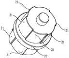
图1为本实用新型旋转模组一实施例的结构示意图;Fig. 1 is a structural schematic diagram of an embodiment of the utility model rotary module;
图2为图1所示实施例中的转轴的结构示意图;Fig. 2 is a schematic structural view of the rotating shaft in the embodiment shown in Fig. 1;
图3为图1所示实施例中的旋转模组的爆炸图;Fig. 3 is the exploded view of the rotary module in the embodiment shown in Fig. 1;
图4为图1所示实施例中的旋转模组的部分结构示意图;Fig. 4 is a partial structural schematic diagram of the rotary module in the embodiment shown in Fig. 1;
图5为图1所示实施例中的旋转模组的部分剖切结构图。FIG. 5 is a partially cut-away structure diagram of the rotary module in the embodiment shown in FIG. 1 .
具体实施方式detailed description
下面将结合本实用新型实施例中的附图,对本实用新型实施例中的技术方案进行清楚、完整地描述,显然,所描述的实施例仅仅是本实用新型的一部分实施例,而不是全部的实施例。基于本实用新型中的实施例,本领域普通技术人员在没有作出创造性劳动前提下所获得的所有其他实施例,都属于本实用新型保护的范围。The technical solutions in the embodiments of the present invention will be clearly and completely described below in conjunction with the accompanying drawings in the embodiments of the present invention. Obviously, the described embodiments are only part of the embodiments of the present invention, not all of them. Example. Based on the embodiments of the present utility model, all other embodiments obtained by persons of ordinary skill in the art without making creative efforts belong to the scope of protection of the present utility model.
需要说明,本实用新型实施例中所有方向性指示(诸如上、下、左、右、前、后……)仅用于解释在某一特定姿态(如附图所示)下各部件之间的相对位置关系、运动情况等,如果该特定姿态发生改变时,则该方向性指示也相应地随之改变。It should be noted that all directional indications (such as up, down, left, right, front, back...) in the embodiments of the present utility model are only used to explain the relationship between the components in a certain posture (as shown in the accompanying drawings). If the specific posture changes, the directional indication will also change accordingly.
还需要说明的是,当元件被称为“固定于”或“设置于”另一个元件上时,它可以直接在另一个元件上或者可能同时存在居中元件。当一个元件被称为是“连接”另一个元件,它可以是直接连接另一个元件或者可能同时存在居中元件。It should also be noted that when an element is referred to as being “fixed” or “disposed on” another element, it can be directly on the other element or intervening elements may also exist. When an element is referred to as being "connected to" another element, it can be directly connected to the other element or intervening elements may also be present.
另外,在本实用新型中涉及“第一”、“第二”等的描述仅用于描述目的,而不能理解为指示或暗示其相对重要性或者隐含指明所指示的技术特征的数量。由此,限定有“第一”、“第二”的特征可以明示或者隐含地包括至少一个该特征。另外,各个实施例之间的技术方案可以相互结合,但是必须是以本领域普通技术人员能够实现为基础,当技术方案的结合出现相互矛盾或无法实现时应当认为这种技术方案的结合不存在,也不在本实用新型要求的保护范围之内。In addition, the descriptions related to "first", "second" and so on in the present application are only for the purpose of description, and should not be understood as indicating or implying their relative importance or implicitly specifying the quantity of the indicated technical features. Thus, the features defined as "first" and "second" may explicitly or implicitly include at least one of these features. In addition, the technical solutions of the various embodiments can be combined with each other, but it must be based on the realization of those skilled in the art. When the combination of technical solutions is contradictory or cannot be realized, it should be considered that the combination of technical solutions does not exist , also not within the scope of protection required by the utility model.
本实用新型提出一种旋转模组,可应用于摄影器材(例如,魔术转接头、快拆板、手柄、三脚架和上手提等),作为摄影器材的旋转关节;安装有该旋转模组的摄影器材,可与另一摄影器材通过旋转模组转动相连,将其中一摄影器材与摄影设备相连,即可以快速方便对摄影设备进行转动调节和锁定。The utility model proposes a rotary module, which can be applied to photographic equipment (such as magic adapters, quick release plates, handles, tripods, and upper handles, etc.), as the rotary joint of photographic equipment; the photographic equipment equipped with the rotary module The equipment can be rotatably connected with another photographic equipment through the rotating module, and one of the photographic equipment can be connected with the photographic equipment, so that the photographic equipment can be rotated, adjusted and locked quickly and conveniently.
参照图1至图5,在本实施例中,该旋转模组包括外壳10、转轴20和两个环形保持架30,其中:1 to 5, in this embodiment, the rotary module includes a
外壳10设有安装孔11,本实施例图中仅以外壳10的两端敞口设置(即安装孔11的两端贯穿外壳10)为例,当然,在其它实施例中,外壳10还可以是一端设置开口;The
两个环形保持架30沿安装孔11的轴向依次转动设于安装孔11内;两环形保持架30内具有轴向通孔,转轴20穿插于两环形保持架30中,即插在两环形保持架30的轴向通孔中;The two
环形保持架30设有沿其周向分布的多个安装槽31,安装槽31中设有滚动组件32,转轴20的外周壁对应安装槽31设有凸起的抵接部21,至少一滚动组件32位于抵接部21与安装孔11内壁之间;沿转轴20的同一周向(例如,顺时针方向或逆时针方向),一个环形保持架30对应的抵接部21的凸起高度逐渐增大,另一个环形保持架30对应的抵接部21的凸起高度逐渐减小,即两个环形保持架30对应的抵接部21的凸起高度的增大方向相反。The
本实施例的旋转模组的工作原理为:1、在需要锁定旋转模组时,通过相对外壳10朝第一方向(例如,顺时针方向或逆时针方向)转动一个环形保持架30(为方便理解和后续描述,记为第一环形保持架30),以及相对外壳10朝第一方向的反方向(记为第二方向)转动另一个环形保持架30(记为第二环形保持架30),使两个环形保持架30的滚动组件32移动到抵接部21凸起较高的一端与安装孔11内壁之间,滚动组件32的两侧分别抵紧抵接部21和安装孔11内壁,如此,滚动组件32与抵接部21之间的摩擦力增大,滚动组件32与安装孔11内壁之间的摩擦力也增大,使转轴20通过滚动组件32与外壳10实现锁定;并且,由于两个环形保持架30对应的抵接部21的凸起高度增大方向相反,因此,当滚动组件32抵紧在抵接部21和安装孔11内壁之间时,无论是顺时针还是逆转动转轴20或外壳10,都会使其中一个环形保持架30的滚动组件32分别与抵接部21和外壳10抵紧的更紧,可以保证锁定状态稳定可靠。2、在需要解锁旋转模组时,通过相对外壳10朝第二方向转动第一环形保持架30,以及相对外壳10朝第一方向转动第二环形保持架30,使两个环形保持架30的滚动组件32从抵接部21凸起较高的一端与安装孔11内壁之间,移动至抵接部21凸起较低的一端与安装孔11内壁之间,滚动组件32不在抵紧抵接部21和安装孔11内壁,滚动组件32的两侧分别抵紧抵接部21和安装孔11内壁,如此,滚动组件32与安装孔11内壁及抵接部21之间的摩擦力大幅降低,滚动组件32可相对外壳10和抵接部21自由转动,实现转轴20与外壳10之间的解锁。The working principle of the rotary module of this embodiment is: 1. When the rotary module needs to be locked, rotate an
本实施例的旋转模组在摄影器材上使用时,外壳10与一个摄影器材连接,转轴20则与另一个摄影器材连接,这样,两个摄影器材就可以通过将旋转模组调至解锁状态时,以转动调节两个摄影器材之间的角度,以及通过将旋转模组调至锁定状态,以将两个摄影器材固定在当前角度。When the rotary module of this embodiment is used on photographic equipment, the
本实施例的旋转模组,采用在外壳10的安装孔11中转动设置两个环形保持架30,在环形保持架30中插设转轴20,环形保持架30周向设置安装有滚动组件32的安装槽31,转轴20外壁设置与滚动组件32对应的抵接部21,两个环形保持架30对应的抵接部21的凸起高度的增大方向相反;如此,通过异向转动(即分别朝相反的方向转动)两个环形保持架30,使滚动组件32移动至抵紧在抵接部21与安装孔11内壁之间,即可实现旋转模组的锁定;以及通过异向转动两个环形保持架30,使滚动组件32移动至与抵接部21和安装孔11内壁的脱离抵紧状态,即可实现旋转模组的解锁。因此,本实施例的旋转模组应用作为摄像器件之间的连接件时,可使摄像器材快速进行角度调节和角度锁定,更加方便用户快速调节所需的拍摄角度。In the rotary module of this embodiment, two
参阅图2至图5,在本实施例中,转轴20的外周壁上设有位于两环形保持架30之间的限位部22。通过设置该限位部22,使转轴20产生沿轴向的移动的趋势时,限位部22会被该移动趋势方向上的环形保持架30给阻挡,可有效防止转轴20在轴向上的晃动,保证了转轴20相对外壳10转动的稳定性,保证了使用该旋转模组的摄影组件或摄影设备的拍摄稳定性。优选地,限位部22轴向的两侧分别抵接两环形保持架30。Referring to FIG. 2 to FIG. 5 , in this embodiment, the outer peripheral wall of the
在一些实施例中,限位部22为与转轴20同轴的环形卡台,环形卡台的外径与安装孔11的内径适配。通过进一步将限位部22设计成环形卡台,且环形卡台的外周壁与安装孔11的内壁贴合,如此,一方面可以使转轴20的重心不偏移轴心,提升转轴20转动的稳定性,另一方面通过环形卡台的外周壁与安装孔11的内壁的限位,可以防止转轴20转动过程中产生偏心的情况,确保转轴20稳定绕其轴心转动,进一步提升,旋转模组的转动稳定性。In some embodiments, the limiting
当然,在其他实施例中,限位部22还可为沿转轴20的周向均匀间隔分布的多个凸台,等等。Of course, in other embodiments, the limiting
在一些实施例中,滚动组件32包括至少一个滚动体。本实施例中,滚动组件32以包括一个滚动体,且滚动体以圆柱为例。当然,在其他实施例中,滚动组件32还可以包括多个滚动体,多个滚动体可并排分布或同轴分布,滚动体也还可为圆珠、圆轮、圆盘等。In some embodiments, rolling
参阅图3和图5,在本实施例中,外壳10的两端分别设有与安装孔11同轴的限位台阶12,两环形保持架30相互远离的一端均设有环形卡边33,两环形保持架30的环形卡边33分别适配卡在外壳10两端的限位台阶12中。本实施例通过在外壳10的两端分别设置限位台阶12,且在环形保持架30的外端设置与限位台阶12适配的环形卡边33,如此,环形保持架30在与外壳10进行安装时,只需将环形保持架30的内端从安装孔11的一端插入,并使环形卡边33卡在限位台阶12,即可实现环形保持架30的快速定位安装,既提升了环形保持架30的安装速度,又保证了环形保持架30的安装精度。Referring to Fig. 3 and Fig. 5, in this embodiment, the two ends of the
在一些实施例中,两环形保持架30相互远离的一端均设有手持部40,通过设置手持部40,更方便用户对环形保持架30进行转动操作。本实施例图中,手持部40以包括与环形保持架30的轴心平行的操作杆为例,当然,在其他实施例中,手持部40还可为其它结构。In some embodiments, the ends of the two
在一些实施例中,旋转模组还包括复位弹簧(图中未示),复位弹簧一端连接手持部40,复位弹簧的另一端连接外壳10,复位弹簧驱动滚动组件32抵接转轴20,以固定转轴20。也就是说,复位弹簧对手持部40产生弹性作用力,使手持部40保持驱动环形保持架30带着滚动组件32朝抵紧转轴20的抵接部21和安装孔11内壁的状态运动的趋势,从而使滚动组件32保持抵接转轴20的抵接部21和安装孔11内壁,即使旋转模组保持在锁定状态,以将转轴20固定。In some embodiments, the rotary module further includes a return spring (not shown in the figure), one end of the return spring is connected to the
在一些实施例中,两环形保持架30的手持部40还可通过联动组件连接,在一个手持部40驱动其环形保持架30朝第一方向转动时,联动组件带动另一手持部40同步驱动器环形保持架30朝第一方向的反方向转动,如此,可以使得旋转模组的解锁和锁定操作更加简便。In some embodiments, the
在一些实施例中,抵接部21到转轴20轴心的最大距离与最小距离的差值为L,L即为抵接部21朝安装孔11内壁推动滚动组件32移动的距离范围,其中L为0.3~1.5mm,例如L为0.5、0.7、0.9、1、1.2、1.3mm。In some embodiments, the difference between the maximum distance and the minimum distance from the abutting
在一些实施例中,抵接部21到转轴20轴心的最大距离与最小距离的差值L在0.5mm以内。In some embodiments, the difference L between the maximum distance and the minimum distance from the abutting
在一些实施例中,L与滚动组件32的半径的比值为0.1~0.6,例如0.5、0.4、0.3。In some embodiments, the ratio of L to the radius of the rolling
在一些实施例中,抵接部21到转轴20轴心的最大距离与最小距离的差值为L,安装孔11的直径为R,L与R的比值为0.012~0.05,例如0.01、0.015、0.025、0.03、0.04、0.045。In some embodiments, the difference between the maximum distance and the minimum distance from the abutting
旋转组件通过采用上述实施例中的尺寸数据,可以保证旋转组件的转动调节和锁定状态都非常稳定可靠。By adopting the dimensional data in the above-mentioned embodiments, the rotation assembly can ensure that the rotation adjustment and locking state of the rotation assembly are very stable and reliable.
在一些实施例中,外壳10为一体的圆管状壳体,采用一体的外壳10,一方面保证了外壳10的强度,另一方面可以减少旋转模组的组成部件的数量,使整体结构更加的简单。进一步地,圆管状壳体的外径在25mm以内,本实施例的旋转模组将外壳10设计成外径25mm以内,整体尺寸小巧,可安装在摄影器材中的各种狭小空间中,通用性强,并且小巧的尺寸实现隐藏式安装,可不裸露在摄影器材的外部,使摄影器材保证整体的外观简洁。In some embodiments, the
本实用新型还提出一种摄影组件,包括旋转模组、第一摄影器材和第二摄影器材,该旋转模组的具体结构参照上述实施例,由于本摄影组件采用了上述旋转模组所有实施例的全部技术方案,因此至少具有上述实施例的技术方案所带来的所有有益效果,在此不再一一赘述。其中,第一摄影器材与旋转模组的外壳10连接,第二摄影器材与旋转模组的转轴20连接;第一摄影器材和第二摄影器材其中之一可与摄影设备(照相机或摄像机)相连。The utility model also proposes a photographic assembly, including a rotating module, a first photographic equipment, and a second photographic equipment. The specific structure of the rotating module refers to the above-mentioned embodiments, because the photographic assembly adopts all the embodiments of the above-mentioned rotating module. All the technical solutions of the present invention, therefore at least have all the beneficial effects brought by the technical solutions of the above-mentioned embodiments, and will not be repeated here. Wherein, the first photographic equipment is connected with the
以上所述的仅为本实用新型的部分或优选实施例,无论是文字还是附图都不能因此限制本实用新型保护的范围,凡是在与本实用新型一个整体的构思下,利用本实用新型说明书及附图内容所作的等效结构变换,或直接/间接运用在其他相关的技术领域均包括在本实用新型保护的范围内。What is described above is only a part or preferred embodiment of the present utility model, and neither words nor accompanying drawings can limit the protection scope of the present utility model. and the equivalent structural transformation made by the content of the accompanying drawings, or directly/indirectly used in other related technical fields are all included in the protection scope of the present utility model.
Claims (10)
Translated fromChinesePriority Applications (3)
| Application Number | Priority Date | Filing Date | Title |
|---|---|---|---|
| CN202222393163.3UCN218178456U (en) | 2022-09-07 | 2022-09-07 | Rotary module and camera module |
| US18/462,381US20240077170A1 (en) | 2022-09-07 | 2023-09-06 | Composite bearing, rotating assembly, and photographic assembly |
| EP23195803.4AEP4338882A1 (en) | 2022-09-07 | 2023-09-06 | Composite bearing, rotating assembly, and photographic assembly |
Applications Claiming Priority (1)
| Application Number | Priority Date | Filing Date | Title |
|---|---|---|---|
| CN202222393163.3UCN218178456U (en) | 2022-09-07 | 2022-09-07 | Rotary module and camera module |
Publications (1)
| Publication Number | Publication Date |
|---|---|
| CN218178456Utrue CN218178456U (en) | 2022-12-30 |
Family
ID=84623889
Family Applications (1)
| Application Number | Title | Priority Date | Filing Date |
|---|---|---|---|
| CN202222393163.3UActiveCN218178456U (en) | 2022-09-07 | 2022-09-07 | Rotary module and camera module |
Country Status (1)
| Country | Link |
|---|---|
| CN (1) | CN218178456U (en) |
Cited By (1)
| Publication number | Priority date | Publication date | Assignee | Title |
|---|---|---|---|---|
| CN115451281A (en)* | 2022-09-07 | 2022-12-09 | 深圳市乐其网络科技有限公司 | Rotary modules and photography equipment |
- 2022
- 2022-09-07CNCN202222393163.3Upatent/CN218178456U/enactiveActive
Cited By (1)
| Publication number | Priority date | Publication date | Assignee | Title |
|---|---|---|---|---|
| CN115451281A (en)* | 2022-09-07 | 2022-12-09 | 深圳市乐其网络科技有限公司 | Rotary modules and photography equipment |
Similar Documents
| Publication | Publication Date | Title |
|---|---|---|
| CN113950596B (en) | Quick release connection components, handheld gimbal and shooting equipment | |
| US20130146742A1 (en) | Reconfigurable monopod mounting system | |
| CN218178456U (en) | Rotary module and camera module | |
| WO2017080337A1 (en) | Photographic extension bar and shooting device | |
| US20080210832A1 (en) | Support For Video/Photographic Equipment | |
| US11906101B2 (en) | Photographic equipment assembly and quick connection assembly thereof | |
| JP7005730B2 (en) | Filter mounting structure | |
| CN106534648B (en) | A kind of photographic device and the terminal with the photographic device | |
| WO2019114386A1 (en) | Camera structure and pan-tilt thereof | |
| CN114198373B (en) | Clips and photographic equipment | |
| CN115451281A (en) | Rotary modules and photography equipment | |
| CN218543715U (en) | Rotating structure and shooting auxiliary device with same | |
| CN116518223A (en) | Tripod stand | |
| CN215891791U (en) | Locking mechanism, cloud platform and supplementary shooting equipment | |
| CN112483822B (en) | PTZ and its dynamic balance adjustment structure | |
| CN218720167U (en) | Rotary Modules and Camera Components | |
| CN115306818A (en) | Rotating structure and shooting auxiliary device | |
| CN211315626U (en) | PTZ and its dynamic balance adjustment structure | |
| CN220186259U (en) | Rotation locking limiting device | |
| CN208951560U (en) | Quick-locking device and apparatus for making a video recording component for apparatus for making a video recording | |
| CN213957811U (en) | Annular flash lamp assembly and support thereof | |
| CN222616510U (en) | Center shaft assembly and support foot rest | |
| CN117345738A (en) | Quick release parts | |
| CN218630490U (en) | Ring adjustment bracket | |
| CN219140452U (en) | Foldable storage handle assembly and photographic camera support |
Legal Events
| Date | Code | Title | Description |
|---|---|---|---|
| GR01 | Patent grant | ||
| GR01 | Patent grant | ||
| CP03 | Change of name, title or address | ||
| CP03 | Change of name, title or address | Address after:Room 103, 501, 601, Building 5, Fenghe Industrial Park, No. 1301-50, Sightseeing Road, Xinlan Community, Guanlan Street, Longhua District, Shenzhen, Guangdong 518000 Patentee after:Shenzhen Leqi Innovation Co.,Ltd. Country or region after:China Address before:Room 103, 501, 601, Building 5, Fenghe Industrial Park, No. 1301-50, Sightseeing Road, Xinlan Community, Guanlan Street, Longhua District, Shenzhen, Guangdong 518000 Patentee before:SHENZHEN LEQI NETWORK TECHNOLOGY Co.,Ltd. Country or region before:China | |
| CP03 | Change of name, title or address | ||
| CP03 | Change of name, title or address | Address after:No. 58 Ping'an Road, Dafu Community, Guanlan Street, Longhua District, Shenzhen City, Guangdong Province 518000, China Patentee after:Shenzhen Leqi Innovation Co.,Ltd. Country or region after:China Address before:Room 103, 501, 601, Building 5, Fenghe Industrial Park, No. 1301-50, Sightseeing Road, Xinlan Community, Guanlan Street, Longhua District, Shenzhen, Guangdong 518000 Patentee before:Shenzhen Leqi Innovation Co.,Ltd. Country or region before:China |