CN217987637U - Stitching instrument - Google Patents
Stitching instrumentDownload PDFInfo
- Publication number
- CN217987637U CN217987637UCN202221760550.XUCN202221760550UCN217987637UCN 217987637 UCN217987637 UCN 217987637UCN 202221760550 UCN202221760550 UCN 202221760550UCN 217987637 UCN217987637 UCN 217987637U
- Authority
- CN
- China
- Prior art keywords
- nail
- anvil
- nail bin
- stapler
- groove
- Prior art date
- Legal status (The legal status is an assumption and is not a legal conclusion. Google has not performed a legal analysis and makes no representation as to the accuracy of the status listed.)
- Active
Links
Images


Landscapes
- Surgical Instruments (AREA)
Abstract
Translated fromChinese
Description
Translated fromChinese技术领域technical field
本实用新型涉及医疗器械领域,涉及一种用于缝合器。The utility model relates to the field of medical instruments, in particular to a suturing device.
背景技术Background technique
由于现代科学技术的发展,诞生了替代传统手工缝合的切割吻合器;切割吻合器具有吻合迅速、可靠、术后并发症少等优点。其工作原理类似于订书机,即利用钛钉和刀片分别对组织和器官进行吻合切割的过程。已有的切割吻合器主要是用于皮肤、消化道、血管、肺等的切割吻合,可适用于腹腔镜和开放手术。很多管腔样体内结构(如泌尿道:包括尿道、膀胱尿道、输尿管膀胱、输尿管;肠道、血管等)的修复重建目前临床上主要依赖于手工带线吻合和使用腔内圆形吻合器或者多个直线型切割吻合器吻合。Due to the development of modern science and technology, a cutting stapler that replaces traditional manual suturing has been born; the cutting stapler has the advantages of rapid anastomosis, reliability, and fewer postoperative complications. Its working principle is similar to that of a stapler, that is, the process of stapling and cutting tissues and organs with titanium nails and blades, respectively. Existing cutting staplers are mainly used for cutting and anastomosis of skin, digestive tract, blood vessels, lungs, etc., and are suitable for laparoscopic and open operations. The repair and reconstruction of many lumen-like internal structures (such as urinary tract: including urethra, vesicourethra, ureteral bladder, ureter; intestinal tract, blood vessels, etc.) currently mainly rely on manual anastomosis with wires and the use of endoluminal circular staplers or Multiple linear cutting staplers are used for anastomosis.
目前临床使用的腔内缝合器主要适用于消化道重建的侧侧缝合,需要使用多个直线型切割缝合器或钉仓。这种缝合方式至少有三个缺陷:(1)改变了人体正常解剖结构,缝合钉交界处术后容易出现缝合口组织坏死、缝合瘘、出血;(2) 缝合后,管腔内容物通过造瘘口时,在管腔内形成90°的转向,不够畅通,容易引起梗阻;(3)需要进行两次或多次缝合,大大增加了手术费用和手术难度。除此之外,已有的腔内切割缝合器在胆道、输卵管、输尿管、尿道等较小管腔缝合中均无能为力,或仅能行使闭合切割功能。下面结合附图详细说明现有技术的存在的问题。The current clinically used endoluminal staplers are mainly suitable for side-to-side suturing of digestive tract reconstruction, requiring the use of multiple linear cutting staplers or staple cartridges. This suture method has at least three defects: (1) It changes the normal anatomical structure of the human body, and the suture junction is prone to tissue necrosis, suture fistula, and bleeding after surgery; (2) After suturing, the contents of the lumen pass through the stoma When opening the mouth, a 90° turn is formed in the lumen, which is not smooth enough and can easily cause obstruction; (3) two or more sutures are required, which greatly increases the cost and difficulty of the operation. In addition, the existing endoluminal cutting and staplers are powerless in suturing small lumens such as biliary tract, fallopian tube, ureter, and urethra, or can only perform closed cutting function. The existing problems of the prior art will be described in detail below in conjunction with the accompanying drawings.
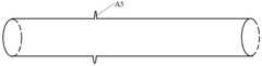
如图1所示,手术中形成两段待缝合的管腔,需要将管腔的端端缝合在起来。As shown in FIG. 1 , two lumens to be sutured are formed during the operation, and the ends of the lumens need to be sutured together.
结合图2、3、5,是目前常用的内翻吻合手术,首先在右端的管腔上开一个创口A1,将图3中的端部弯曲的吻合器伸进管腔中,吻合器的操作手柄位于管腔外部,牵拉管腔的两个断端到圆形钉砧A8、圆形钉仓A9之间,推动推钉座A11 击发圆形钉仓A10中的吻合钉,将管腔的两断端钉在一起,环形刀片A9将多余的组织切除,从而且形成图2中的一圈内翻缝合管腔组织A2。然后将吻合器通过创口A1从管腔中拿出来,再使用图5中的吻合器将创口A1缝合起来。这种缝合方式至少有三个缺陷:(1)采用内翻式吻合,在管腔中形成突出管腔内壁的内翻缝合管腔组织A2,很容易在术后造成狭窄、梗阻等诸多并发症。(2)需要在管腔上开一个创口A1并且需要再次吻合,该创口是因手术需要额外开设的,增加了手术难度,也给病人增加了不必要的痛苦。(3)使用多种吻合器,大大增加了手术费用。Combined with Figures 2, 3, and 5, it is a commonly used varus anastomosis operation. First, an incision A1 is made on the lumen at the right end, and the stapler with a curved end in Figure 3 is inserted into the lumen. The operation of the stapler The handle is located outside the lumen, pull the two broken ends of the lumen between the circular staple anvil A8 and the circular staple magazine A9, push the pusher seat A11 to fire the staples in the circular staple magazine A10, and place the staples in the lumen The two broken ends are nailed together, and the excess tissue is excised by the annular blade A9, thereby forming a circle of sutured lumen tissue A2 in Fig. 2 . Then take the stapler out of the lumen through the wound A1, and then use the stapler shown in Figure 5 to suture the wound A1. This suturing method has at least three defects: (1) Inverted anastomosis is used to form an inverted suture lumen tissue A2 protruding from the inner wall of the lumen in the lumen, which is easy to cause many complications such as stenosis and obstruction after the operation. (2) An incision A1 needs to be made on the lumen and needs to be anastomosed again. This incision is additionally opened due to the operation, which increases the difficulty of the operation and also increases unnecessary pain for the patient. (3) Use multiple staplers, greatly increasing the cost of surgery.
结合图4、5,这是第二种吻合方式,将图1中的右端管腔进行牵拉,将两断端并列摆放,使得两管腔外壁贴在一起,再利用图5所示的直线型吻合器将贴在一起的管腔侧侧吻合起来,即,将两贴在一起的管腔壁放在钉仓A6、钉砧A7之间,击发钉仓A6中的吻合钉将两段管腔的管腔壁吻在一起,然后在吻合起来的部位开设一个造瘘口A3,最后再将两段管腔的端部通过图5所示的直线型吻合器吻合起来。造瘘口A3就成了两段管腔的连通口。这种吻合方式至少有三个缺陷:(1)由于需要改变其中一段管腔的原有走向,通过外力牵拉管腔,这种方式本身就会对管腔造成损害。(2)吻合后,管腔中的流动内容物通过造瘘口A3移动,在管腔内形成90°的转向,流动不够畅通,容易阻塞。(3)需要进行两次或多次吻合,大大增加了手术费用和手术难度。Combined with Figures 4 and 5, this is the second anastomosis method. Pull the lumen at the right end in Figure 1, place the two broken ends side by side, so that the outer walls of the two lumens stick together, and then use the lumen at the right end as shown in Figure 5. The linear stapler anastomoses the lumen side by side, that is, puts the two lumen walls affixed together between the staple magazine A6 and the anvil A7, and fires the staples in the staple magazine A6 to separate the two segments. The lumen walls of the lumen are anastomosed together, and then an ostomy opening A3 is opened at the anastomosed part, and finally the ends of the two lumens are anastomosed by the linear stapler shown in FIG. 5 . The ostomy port A3 has just become the communicating port of the two sections of the lumen. This anastomotic method has at least three defects: (1) Since the original orientation of a section of the lumen needs to be changed, the lumen is pulled by external force, and this method itself will cause damage to the lumen. (2) After the anastomosis, the flowing content in the lumen moves through the stoma A3, forming a 90° turn in the lumen, the flow is not smooth enough, and it is easy to block. (3) Two or more anastomoses are required, which greatly increases the cost and difficulty of the operation.
图6示出的是外翻式缝合方式,将两断端外翻,缝合后形成一圈外翻缝合管腔组织A5,该方式的优点是显而易见的,缝合点在管腔外部,不会造成术后狭窄、梗阻等并发症。但在目前的手术中,这种方式仅限于人工缝合,无法使用吻合器。可以结合图3来说明,如果将两段管腔的断端分别外翻在圆形钉砧A8、圆形钉仓A10上,然后缝合起来,缝合后没有办法将吻合器从缝合后的管腔上拿下来。为实现吻合器的外翻式吻合,申请号为201510282427X的发明专利提供了一种一种腔外吻合方法,该方法在管腔缝合后,用剪刀剪断钉仓和底座的环形结构,从而拆除钉仓和底座。但该方法仅仅是一个想法,并未给出详细的结构特征,至少有四个原因导致其无法在临床上应用:(1)手术空间非常小,很难在缝合后在组织和吻合环之间另外伸入一把剪刀将环形结构剪断。(2)利用剪刀剪断环形结构时,需要施加外力,如果操作不当会对管腔组织造成二次损害,甚至拽断管腔。(3)剪刀容易剪断破坏的材料其刚性必然不足,不足以形成足够的吻合牵引力,对手术剪亦具有破坏性。(4)采用了牵拉钉砧环向近端挤压吻合钉的吻合方式,因为术中无法窥及远端情况,容易造成组织脏器撕裂。Figure 6 shows the valgus suture method, in which the two ends are valgus, and a circle of valgus suture lumen tissue A5 is formed after suturing. The advantages of this method are obvious, and the suture point is outside the lumen, without causing Postoperative complications such as stenosis and obstruction. However, in the current operation, this method is limited to manual suturing, and staplers cannot be used. It can be illustrated in conjunction with Figure 3 that if the broken ends of the two sections of the lumen are turned outward on the circular anvil A8 and the circular staple cartridge A10 respectively, and then sutured together, there is no way to separate the stapler from the sutured lumen after suturing. take it down. In order to realize the eversion-type anastomosis of the stapler, the invention patent with the application number of 201510282427X provides an extraluminal anastomosis method. After the lumen is sutured, the annular structure of the staple cartridge and the base is cut off with scissors, thereby removing the staples. Bin and base. However, this method is only an idea, and no detailed structural features are given. There are at least four reasons why it cannot be applied clinically: (1) The operation space is very small, and it is difficult to insert the tissue between the anastomotic ring after suturing. An additional pair of scissors is inserted to cut the ring structure. (2) When using scissors to cut the annular structure, external force needs to be applied. If the operation is not done properly, it will cause secondary damage to the lumen tissue, or even break the lumen. (3) The rigidity of materials that are easy to be cut and damaged by scissors must be insufficient to form sufficient anastomotic traction, which is also destructive to surgical scissors. (4) The anastomosis method of pulling the anvil ring to the proximal end to squeeze the staples is adopted, because the distal end cannot be seen during the operation, which may easily cause tearing of the tissues and organs.
发明内容Contents of the invention
本实用新型的目的在于提供一种用于外翻式缝合器的执行机构,使缝合器可以经鞘卡等微通道进行人体内进行腔内端-端、端-侧、侧-侧等外翻式缝合。The purpose of this utility model is to provide an actuator for an eversion-type suturing device, so that the suturing device can perform end-to-end, end-to-side, and side-to-side valgus in the human body through micro-channels such as sheath cards. suture.
本实用新型提供的缝合器,包括钉仓机构、钉砧机构、传动机构、击发控制机构和壳体,所述击发控制机构安装在壳体上,所述壳体包括前半壳体和后半壳体;所述钉仓机构包括钉仓盖、钉仓座,所述钉仓盖与钉仓座之间的空间内设置有推钉机构,所述钉砧机构包括钉砧座;所述传动机构包括传动机构弹片;The suturing device provided by the utility model includes a staple bin mechanism, an anvil mechanism, a transmission mechanism, a firing control mechanism and a casing, the firing control mechanism is installed on the casing, and the casing includes a front half casing and a rear half casing Body; the staple cartridge mechanism includes a staple cartridge cover and a staple cartridge seat, a nail pushing mechanism is arranged in the space between the staple cartridge cover and the staple cartridge seat, and the nail anvil mechanism includes a nail anvil seat; the transmission mechanism Including shrapnel of the transmission mechanism;
所述钉仓盖、钉仓座、钉砧座上分别设置有沿执行机构长度方向延伸的穿入槽,该穿入槽在钉仓盖、钉仓座、钉砧座的远端形成有开口;在所述穿入槽的两侧,所述钉仓盖、钉砧座上还设置有沿执行机构长度方向延伸的导引槽;所述钉仓机构内的缝合钉分列所述穿入槽的两侧,位于所述穿入槽与导引槽之间;The nail bin cover, the nail bin seat, and the nail anvil are respectively provided with penetration grooves extending along the length direction of the actuator. ; On both sides of the penetration groove, the staple cartridge cover and the staple anvil are also provided with guide grooves extending along the length direction of the actuator; the staples in the staple cartridge mechanism are listed in the penetration The two sides of the groove are located between the penetration groove and the guide groove;
所述传动机构弹片包括传动机构弹片A、传动机构弹片B,所述传动机构弹片A、传动机构弹片B的远端伸入所述钉仓盖与钉仓座之间的空间内,所述推钉机构包括推钉机构A、推钉机构B,所述传动机构弹片A、传动机构弹片B的远端沿所述钉仓盖、钉砧座上的导引槽移动时,分别推动推钉机构A、推钉机构B 在穿入槽的两侧移动。壳体包括前半壳体和后半壳体,方便击发控制机构的安装。The transmission mechanism shrapnel includes a transmission mechanism shrapnel A and a transmission mechanism shrapnel B. The far ends of the transmission mechanism shrapnel A and the transmission mechanism shrapnel B extend into the space between the staple bin cover and the staple bin seat. The nail mechanism includes a nail pushing mechanism A and a nail pushing mechanism B. When the distal ends of the transmission mechanism shrapnel A and the transmission mechanism shrapnel B move along the guide grooves on the nail bin cover and the nail anvil, the nail pushing mechanism is respectively pushed A. Push nail mechanism B moves on both sides of the penetration groove. The casing includes a front half casing and a rear half casing, which facilitates the installation of the firing control mechanism.
本实用新型的重要发明点在于突破了常规的直线型缝合器的设计结构,将钉仓机构、钉砧机构一分为二,在中部设置穿入槽,从而可以将两个待缝合组织的断端分别从钉仓机构的穿入槽、钉砧机构的穿入槽牵引穿入,然后向外翻开待缝合组织断端,即可实现端端缝合,缝好后,再从穿入槽中移出,使得直线型缝合器也可以进行外翻缝合。本实用新型的方案设计思路精巧,只需要对常规的直线型缝合器进行改动,即可实现外翻缝合。The important invention point of this utility model is that it breaks through the design structure of the conventional linear stapler, divides the staple magazine mechanism and the nail anvil mechanism into two, and sets a penetration groove in the middle, so that the two broken tissues to be sutured can be The ends are drawn and penetrated from the penetration groove of the staple magazine mechanism and the penetration groove of the nail anvil mechanism respectively, and then the broken end of the tissue to be sutured is turned outward to realize end-to-end suture. Move out so that the linear stapler can also perform everted sutures. The scheme design idea of the utility model is exquisite, only need to change the conventional linear suturing device, can realize valgus suturing.
优选地,所述导引槽包括近端的第一导引段、远端的第二导引段以及连接所述第一导引段和第二导引段的连接段,其中两条第一导引段之间的距离小于两条第二导引段的距离。在近端,传动机构弹片A、传动机构弹片B离得比较近,向远端移动后,利用传动弹片形变能力,传动机构弹片A、传动机构弹片B分离得较远,第二导引段的设计方式,避免了对缝合钉等的干扰。同时,可以在穿入槽的近端布置缝合钉,传动弹片在近端离得近,可以在近端沿着连接段击发缝合钉。Preferably, the guide groove includes a first guide segment at the proximal end, a second guide segment at the distal end, and a connecting segment connecting the first guide segment and the second guide segment, wherein the two first guide segments The distance between the guide segments is smaller than the distance between the two second guide segments. At the proximal end, the shrapnel A of the transmission mechanism and the shrapnel B of the transmission mechanism are relatively close. After moving to the far end, the shrapnel A of the transmission mechanism and the shrapnel B of the transmission mechanism are separated far away by using the deformation ability of the transmission shrapnel. Designed in such a way that interference with staples and the like is avoided. Simultaneously, staples can be arranged at the proximal end of the penetration groove, and the driving shrapnel is close at the proximal end, and the staples can be fired along the connecting section at the proximal end.
优选地,在所述钉仓座的穿入槽的近端设置有缝合钉,这样设计,可以确保穿入槽的两侧以及近端的待缝合组织都可以得到缝合,将缝合后的肠道组织移出穿入槽,再人工将起初位于穿入槽远端的肠道组织补针缝合即可完成整体缝合。Preferably, staples are arranged at the proximal end of the penetration groove of the staple cartridge seat, and this design can ensure that both sides of the penetration groove and the tissue to be sutured at the proximal end can be sutured, and the sutured intestinal tract The tissue is moved out of the trough, and the intestinal tissue at the far end of the trough is manually sutured to complete the whole suture.
优选地,两侧的导引槽自远端至近端均平行设置。此时,缝合钉在钉仓座的穿入槽两侧平行分布,通过执行机构可以将位于两侧的待缝合组织断端缝合起来,将缝合后的组织移出穿入槽,再人工将起初位于穿入槽两端的组织补针缝合即可完成整体缝合。Preferably, the guiding grooves on both sides are arranged in parallel from the distal end to the proximal end. At this time, the suturing staples are distributed in parallel on both sides of the penetration groove of the staple cartridge seat, and the broken ends of the tissue to be sutured on both sides can be sutured through the actuator, and the sutured tissue can be moved out of the penetration groove, and then manually inserted The overall suture can be completed by suturing the tissue patching needles at both ends of the slot.
优选地,所述执行机构近端设置有用于将所述传动机构弹片A、传动机构弹片B隔开的分离柱。分离柱可保证传动机构弹片A、传动机构弹片B于近端始终平行分离,并保证前推或转向时两传动机构弹片不会相互干扰。所述分离柱的近端窄远端宽,可采用纺锤形或半纺锤形。Preferably, the proximal end of the actuator is provided with a separation post for separating the spring piece A of the transmission mechanism and the spring piece B of the transmission mechanism. The separation column can ensure that the shrapnel A of the transmission mechanism and the shrapnel B of the transmission mechanism are always separated in parallel at the proximal end, and ensure that the shrapnel of the transmission mechanism will not interfere with each other when pushing forward or turning. The separation column is narrow at the proximal end and wide at the distal end, and can be spindle-shaped or semi-spindle-shaped.
优选地,所述钉仓座可拆卸地设置在所述钉仓盖下方,如此设计则可以在缝合钉用完之后,更换新的钉仓座即可,使得执行机构主体结构可以重复使用。Preferably, the cartridge holder is detachably arranged under the cartridge cover, so that the cartridge holder can be replaced with a new cartridge holder after the staples are used up, so that the main structure of the actuator can be reused.
如果钉仓盖与钉砧座的宽度比较宽,而钉仓座的宽度相对较窄,传动机构弹片A、传动机构弹片B分列钉仓座的两侧,移动时与钉仓座不会产生干涉,否则,需在所述钉仓座上也设置有沿执行机构长度方向延伸的导引槽。If the width of the staple bin cover and the staple anvil is relatively wide, while the width of the staple bin seat is relatively narrow, the transmission mechanism shrapnel A and the transmission mechanism shrapnel B are arranged on both sides of the staple bin seat, and there will be no contact with the staple bin seat when moving. interference, otherwise, a guide groove extending along the length direction of the actuator should also be provided on the cartridge holder.
优选地,所述传动机构弹片A、传动机构弹片B的远端分别连接有截面呈工字型的滑动限位块A、滑动限位块B,所述滑动限位块A、滑动限位块B的上下端分别插入所述钉仓盖、钉砧座上的其中一侧的导引槽中,工字型的顶端、底端分别露在所述钉仓盖、钉砧座上的导引槽外,工字型结构可以确保传动机构弹片沿着导引槽移动,避免脱离导引槽。Preferably, the far ends of the transmission mechanism shrapnel A and the transmission mechanism shrapnel B are respectively connected with a sliding limit block A and a sliding limit block B with an I-shaped cross section, and the sliding limit block A and the sliding limit block are The upper and lower ends of B are respectively inserted into the guide grooves on one side of the nail bin cover and the nail anvil, and the top and bottom ends of the I-shape are respectively exposed to the guide grooves on the nail bin cover and the nail anvil. Outside the groove, the I-shaped structure can ensure that the shrapnel of the transmission mechanism moves along the guide groove to avoid detaching from the guide groove.
优选地,所述推钉机构A、推钉机构B的近端分别设置有连接凹槽,所述滑动限位块A、滑动限位块B竖直部的连接柱可分别插入推钉机构A、推钉机构B 的连接凹槽,从而实现所述传动机构弹片A、传动机构弹片B与所述推钉机构A、推钉机构B之间的可分离式连接。Preferably, the proximal ends of the nail pushing mechanism A and the nail pushing mechanism B are respectively provided with connection grooves, and the connecting columns of the vertical parts of the sliding limit block A and the sliding limit block B can be respectively inserted into the nail pushing mechanism A , The connection groove of the pusher mechanism B, so as to realize the detachable connection between the transmission mechanism shrapnel A, the transmission mechanism shrapnel B and the said pusher mechanism A, pusher mechanism B.
优选地,所述连接凹槽靠近所述推钉机构的外侧设置,所述推钉机构外侧设置有配重块,保证两侧阻力对等、受力平衡,确保推钉时平顺,推钉机构不会出现偏倚。Preferably, the connecting groove is set close to the outer side of the nail pushing mechanism, and a counterweight is arranged on the outer side of the nail pushing mechanism to ensure that the resistance on both sides is equal, the force is balanced, and the nail pushing is smooth, and the nail pushing mechanism There will be no bias.
优选地,所述滑动限位块A、滑动限位块B竖直部的连接柱的下端设置有切割刀片,利用切割刀片将外翻缝合后边缘多余的组织切除。Preferably, a cutting blade is provided at the lower end of the connecting column of the vertical part of the sliding limit block A and the sliding limit block B, and the excess tissue on the edge after the valgus suturing is cut off with the cutting blade.
优选地,所述钉仓盖、钉仓座、钉砧座的开口为外宽内窄的扩口,该结构方便将待缝合断端组织穿入穿入槽。Preferably, the openings of the staple cartridge cover, the staple cartridge seat, and the staple anvil are flared with a wide outside and a narrow inside. This structure facilitates the insertion of the stump tissue to be sutured into the penetration groove.
优选地,所述钉砧座的底部设置有托板,所述托板上也设置有沿执行机构长度方向延伸的穿入槽,所述托板的近端设置有护板。Preferably, a supporting plate is provided at the bottom of the anvil, and a penetration groove extending along the length direction of the actuator is also provided on the supporting plate, and a guard plate is provided at the proximal end of the supporting plate.
优选地,所述钉砧机构与钉仓机构的近端连接处设置有弹性件,该弹性件促使所述钉仓机构、钉砧机构为开口状态,所述传动机构弹片A、传动机构弹片B 向远端移动时,促使钉仓机构、钉砧机构闭合。Preferably, an elastic member is provided at the proximal connection of the anvil mechanism and the staple cartridge mechanism, and the elastic member promotes the opening state of the staple cartridge mechanism and the staple anvil mechanism, and the transmission mechanism shrapnel A and transmission mechanism shrapnel B When moving to the far end, the staple cartridge mechanism and the staple anvil mechanism are urged to close.
优选地,所述钉仓盖、钉砧座向内凹陷,使得执行机构尺寸变小,便于通过鞘卡。Preferably, the staple cartridge cover and the staple anvil are recessed inward, so that the size of the actuator is reduced to facilitate the passage of the sheath.
本实用新型提供了一种全新的腔内外翻缝合器用执行机构,优势如下:(1) 通过该结构可实现通过鞘卡等微创手术通道进行腔内外翻缝合,是开放外翻缝合的强有力补充,虽然都是外翻缝合,但机构作用原理完全不同,适应了临床微创手术要求;(2)使既往微创手术时必须通过缝线外翻缝合的组织和器官(如:血管、泌尿道等)缝合有了新的选择,大大简化了手术难度,并提高了缝合成功率; (3)一次缝合基本即可实现重建目标,相较于既往需要多次缝合,使用多个缝合钉的情况,节省了手术步骤及手术费用;(4)可以实现腔内端-端、端-侧、侧 -侧等外翻式缝合,缝合场景适用广泛;(5)区别于传统切割缝合器,直接对接缝合,不改变组织器官解剖结构及延续性,不破坏空腔脏器等的蠕动功能,对于患者术后脏器功能保留及恢复有利,大大减少了相关并发症的发生;(6)外置缝合钉,缝合后缝合钉位于腔体外,减少了缝合钉相关并发症,如缝合口狭窄、缝合钉相关出血、结石血栓形成等。The utility model provides a brand-new executive mechanism for a cavity-valgus suturing device, and the advantages are as follows: (1) Through this structure, the cavity-valgus suturing can be realized through minimally invasive surgical channels such as sheath clips, and it is a powerful tool for open-valgus suturing. Supplement, although they are all everted sutures, but the principle of the mechanism is completely different, adapting to the requirements of clinical minimally invasive surgery; (2) Tissues and organs that must be sutured with sutures in the previous minimally invasive surgery (such as: blood vessels, urinary tract, etc.) There are new options for suturing, which greatly simplifies the difficulty of surgery and improves the success rate of suturing; (3) One suture can basically achieve the reconstruction goal. (4) End-to-end, end-to-side, side-to-side and other valgus sutures in the cavity can be realized, and the suture scene is widely applicable; (5) Different from traditional cutting and staplers, direct Butt joint suture does not change the anatomical structure and continuity of tissues and organs, and does not destroy the peristaltic function of hollow organs, etc., which is beneficial to the preservation and recovery of postoperative organ functions in patients, and greatly reduces the occurrence of related complications; (6) External Suture staples, after suturing, the staples are located outside the cavity, reducing the complications related to suture staples, such as suture stenosis, staple-related bleeding, and stone thrombosis.
附图说明Description of drawings
图1为两段待吻合的管腔示意图;Figure 1 is a schematic diagram of two sections of the lumen to be anastomosed;
图2为内翻吻合示意图;Figure 2 is a schematic diagram of varus anastomosis;
图3为内翻吻合用吻合器示意图;Fig. 3 is a schematic diagram of a stapler for varus anastomosis;
图4为管腔吻合方式二的示意图;Fig. 4 is a schematic diagram of the second way of lumen anastomosis;
图5为外部吻合用吻合器示意图;Fig. 5 is a schematic diagram of a stapler for external anastomosis;
图6为外翻吻合示意图;Figure 6 is a schematic diagram of valgus anastomosis;
图7为缝合器击发控制机构示意图;Fig. 7 is a schematic diagram of the firing control mechanism of the stapler;
图8为本实用新型执行机构示意图;Figure 8 is a schematic diagram of the utility model actuator;
图9为本实用新型缝合器通过微创通道示意图;Fig. 9 is a schematic diagram of the utility model through the minimally invasive channel of the suturing device;
图10为本实用新型执行机构爆炸图;Fig. 10 is an exploded view of the actuator of the utility model;
图11为本实用新型传动机构及转向机构示意图;Fig. 11 is a schematic diagram of the transmission mechanism and the steering mechanism of the utility model;
图12为本实用新型钉砧示意图;Fig. 12 is a schematic diagram of the utility model nail anvil;
图13为本实用新型钉仓机构(含开口弹片、金属槽、缝合钉、钉揿等)示意图;Fig. 13 is a schematic diagram of the nail magazine mechanism (including opening shrapnel, metal grooves, suture nails, nail presses, etc.) of the utility model;
图14为本实用新型传动机构、推钉机构配合示意图;Figure 14 is a schematic diagram of the cooperation of the transmission mechanism and the push nail mechanism of the utility model;
图15为两断端外翻缝合示意图;Figure 15 is a schematic diagram of eversion suture of two broken ends;
图16为在钉砧上设置平行导引槽结构示意图。Fig. 16 is a schematic view of the structure of setting parallel guide grooves on the anvil.
图中;1-击发控制机构,101-扳机,102-棘条,103-推进杆,104-复位钮, 105-方向调节钮,106-转向推进杆,107-击发保险,108-手柄,109-壳体;In the figure; 1-firing control mechanism, 101-trigger, 102-ratchet, 103-propelling rod, 104-reset button, 105-direction adjustment button, 106-steering propulsion rod, 107-firing safety, 108-handle, 109 -case;
2-套管,201-上半管,202-下半管;2-sleeve, 201-upper half pipe, 202-lower half pipe;
3-限位块,301-限位块A,302-限位块B;3-limiting block, 301-limiting block A, 302-limiting block B;
4-转向机构,401-片状金属杆,402-钩状突起;4-steering mechanism, 401-sheet metal rod, 402-hook-shaped protrusion;
5-传动机构,501-连接部,5031-传动机构弹片A,5032-传动机构弹片B、 5041-滑动限位块A,5042-滑动限位块B,5046-切割刀片,5047-连接柱A,5048- 连接柱B;5-transmission mechanism, 501-connecting part, 5031-transmission mechanism shrapnel A, 5032-transmission mechanism shrapnel B, 5041-sliding limit block A, 5042-sliding limit block B, 5046-cutting blade, 5047-connecting column A , 5048- connecting column B;
6-钉仓机构,601-连接关节,602-钉仓第一导引段,603-锚定机构,604-开口弹片,605-钉仓盖穿入槽,606-钉仓座,607-钉仓第二导引段,608-钉仓刻度线,609-钉孔,610-缝合钉,611-钉揿,612-近端平台,613-钉仓盖扩口,614- 钉仓连接段;615-钉仓座扩口,616-钉仓座穿入槽,617-钉仓盖,619-分离柱;6-Nail cartridge mechanism, 601-connecting joint, 602-the first guide section of the staple cartridge, 603-anchor mechanism, 604-opening shrapnel, 605-nail cartridge cover penetration groove, 606-nail cartridge seat, 607-nail The second guide section of the cartridge, 608-staple cartridge scale line, 609-nail hole, 610-suture staple, 611-nail press, 612-proximal platform, 613-staple cartridge cover flare, 614-nail cartridge connecting section; 615-Nail bin seat expansion, 616-Nail bin seat penetration groove, 617-Nail bin cover, 619-Separation column;
7-钉砧机构,701-缝合钉成型凹坑,702-护板,703-钉砧连接段,704-钉砧第一导引段,705-钉砧穿入槽,706-钉砧第二导引段,707-钉砧扩口,708-托板, 709-托板穿入槽,710-钉砧座,711-钉砧导引槽;7-anvil mechanism, 701-staple forming pit, 702-shield, 703-connecting section of anvil, 704-first guiding section of anvil, 705-anvil penetration groove, 706-second anvil Guide section, 707-anvil flare, 708-supporting plate, 709-supporting plate penetration groove, 710-anvil anvil, 711-anvil guiding groove;
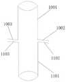
8-推钉机构,801-连接凹槽、802-推钉凸起,803-推钉机构A,804-推钉机构B;9-鞘卡;1001-断端A,1002-外翻部一,1003-外翻部二,1101-断端B, 1102-外翻部三,1103-外翻部四。8-Pushing nail mechanism, 801-connecting groove, 802-pushing nail protrusion, 803-pushing nail mechanism A, 804-pushing nail mechanism B; 9-sheath card; 1001-broken end A, 1002-valgus part 1 , 1003-valgus part two, 1101-stump B, 1102-valgus part three, 1103-valgus part four.
具体实施方式detailed description
下面结合图7-15详细说明本实用新型的技术方案。The technical scheme of the utility model will be described in detail below in conjunction with Fig. 7-15.
为了叙述清晰,我们在附图和下面的描述中使用的方向性术语是相对于操作者右手水平握持缝合器手柄而言的,即固定手柄位于右手虎口中,除拇指外的其余四指握住活动手柄。具体来说,术语“近”和“后”是指靠近操作者的位置,而术语“远”和“前”是指远离操作者的位置。术语“左”是指操作者的左侧,而术语“右”是指操作者的右侧;“上”是指与重力相反的方向,“下”是指重力方向。其他方向性术语可根据附图和下面的描述来理解。In order to clarify the description, the directional terms we use in the drawings and the following description are relative to the operator's right hand holding the handle of the stapler horizontally, that is, the fixed handle is located in the tiger's mouth of the right hand, and the other four fingers except the thumb hold Hold the active handle. Specifically, the terms "proximal" and "rear" refer to a position close to the operator, while the terms "distal" and "anterior" refer to a position remote from the operator. The term "left" refers to the left side of the operator, while the term "right" refers to the right side of the operator; "up" refers to the direction opposite to gravity, and "down" refers to the direction of gravity. Other directional terms can be understood in light of the figures and description below.
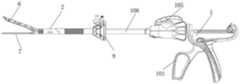
如图7-14所示,本实用新型提供的缝合器包括执行机构、击发控制机构,击发控制机构安装在壳体109上,击发控制机构包括扳机101、棘条102、推进杆103、复位钮104、方向调节钮105、转向推进杆106、击发保险107。壳体上形成有供握持的手柄108,握住手柄108即可操作扳机101,实现单手操作。扳机101与壳体之间设置有复位弹簧,扳动扳机101推动棘条102向前移动,松开扳机101后,复位弹簧促使扳机101复位,为下一次扳动扳机做准备。壳体109 分成两半,方便将击发控制机构的部件安装在壳体上,安装完成后将两半壳体组合在一起即可完成安装,两半壳体拼合后可以用螺丝固定,也可以焊接成一体。图7仅示出了前半壳体,后半壳体未示出。传统直线型切割缝合器可参考 CN101156793A、US5762256B,具体描述了击发控制机构的结构,本申请不再赘述。执行机构通常为一次性装载部件,用完之后废弃,击发控制机构可多次重复使用,并可与传统直线型切割吻合器执行机构相匹配。也可以将一次性装载部件与击发控制机构做成一体的一次性部件。本实用新型的执行机构包括钉仓机构6、钉砧机构7、传动机构5、转向机构4。As shown in Figure 7-14, the stapler provided by the utility model includes an executive mechanism and a firing control mechanism. The firing control mechanism is installed on the
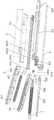
如图11所示,转向机构4包括片状金属杆401,片状金属杆的近端设置有勾状突起402。如图11、14所示,传动机构5包括传动机构弹片A 5031、传动机构弹片B 5032、滑动限位块A 5041、滑动限位块B 5042。传动机构弹片(A、 B)既可以用弹性材料制成,也可以由非弹性材料制成,只要能够产生一定的形变即可。传动机构弹片A与滑动限位块A连接,传动机构弹片B与滑动限位块B 连接。滑动限位块A、滑动限位块B为工字型结构,工字型结构中部的连接柱(连接柱A 5047、连接柱B 5048)的下部设置有切割刀片5046。推钉机构8包括推钉机构A 803、推钉机构B 804,两推钉机构的近端分别开设有连接凹槽801,传动机构弹片A、B分别与推钉机构A、B配合,各推动一个推钉机构,传动机构弹片A、B的连接柱可分别插入推钉机构A、B的连接凹槽801中,连接柱与连接凹槽的配合可以增强推动的稳定性。从图14可以看到,连接凹槽设置在推钉机构的侧部,受力点位于靠近钉仓盖外侧的位置,受力不是特别均匀,在钉仓座穿入槽近端设置缝合钉时,有可能难以击发,为了推钉时平顺,推钉机构不会出现偏倚,可于推钉机构连接凹槽外侧靠近钉仓盖处设置配重块,或连接凹槽外侧后移,使得连接凹槽的深度变深,保证凹槽两侧阻力对等、受力平衡。推钉机构8 的底部设置有推钉凸起802,图中示出了2个推钉凸起,可以击发两排缝合钉,如果缝合钉的排数更多则可以设置更多的推钉凸起,当然,也可以将推钉凸起的厚度增大以覆盖多排的缝合钉。总之,推钉机构8的推钉凸起802的数量根据缝合钉的排数来定,击发缝合钉即可。推钉凸起具有斜面,斜角与钉揿角度相同,方向相对。在钉仓座穿入槽近端,缝合钉向内汇聚。本实施例的传动机构弹片与推钉机构之间通过连接柱与连接凹槽的配合实现可分离式连接,也可以采用固定连接的方式。As shown in FIG. 11 , the
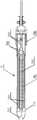
如图8、10所示,转向机构4、传动机构5安装在套管2中。为方便安装,设置了上半管201、下半管202,将传动机构弹片A、传动机构弹片B设置下半管的槽中,再将上半管与下半管拼合,既方便安装又起到导向作用。另外可在远端设置锚定机构603,传动机构弹片A、传动机构弹片B的远端穿过锚定机构603,起到导向作用。传动机构4设置在上下半管拼合后的侧部,然后整体放在套管2 中。下半管的近端设置有限位块3,包括限位块A 301、限位块B302。As shown in FIGS. 8 and 10 , the
如图7、8、9所示,将执行机构近端一侧与直线型切割缝合器击发控制机构 1对合后插入击发控制机构1,并旋转90°,限位块A 301、限位块B 302插入击发控制机构1上相应的孔中,完成两者对接;此时击发控制机构1推进杆103 远端位于传动机构5近端连接部501内并与之啮合,转向机构4近端的钩状突起 402位于转向推进杆106的凹槽内,两者固定连接。As shown in Figures 7, 8, and 9, align the proximal side of the actuator with the firing control mechanism 1 of the linear cutting stapler, insert it into the firing control mechanism 1, and rotate it by 90°, the
如图8、10、13所示,钉仓机构6包括钉仓盖617、钉仓座606。钉仓座606 上设置有钉孔609,缝合钉610放置在钉孔609中,钉揿611位于缝合钉610上方,向下挤压钉揿611,钉揿611向钉砧机构7方向击发缝合钉610。钉仓盖617 盖在钉仓座606上,钉仓盖617与钉仓座606之间具有容纳推钉机构8的空间,使得推钉机构8可以从执行机构近端向远端移动。钉仓盖617的侧部设置有钉仓刻度线608,用于指示钉孔位置,防止组织移位,外翻组织时,组织端部位于钉仓刻度线内,一旦移位很容易发现。本实用新型在钉仓盖的中间设置钉仓盖穿入槽605以及钉仓盖导引槽,钉仓盖穿入槽、钉仓盖导引槽都沿执行机构长度方向从远端向近端延伸,导引槽在穿入槽两侧分布。钉仓盖穿入槽在钉仓盖的远端形成有开口,该开口为外宽内窄的钉仓盖扩口613。钉仓盖导引槽具有两条,分列钉仓盖穿入槽605的两侧。如图中所示,本实用新型导引槽包括钉仓第一导引段 602、钉仓连接端614、钉仓第二导引段607,其中,钉仓第一导引段602延伸到近端平台612,两个钉仓第一导引段602之间的距离小于两个钉仓第二导引段 607的距离,钉仓连接段614连接钉仓第一导引段602、钉仓第二导引段607,形成过渡。钉仓座606上也设置有相应沿执行机构长度方向延伸的、与钉仓盖穿入槽605对应的钉仓座穿入槽616,钉仓座穿入槽616在钉仓座的远端形成有开口,该开口为外宽内窄的钉仓座扩口615。在钉仓座穿入槽的两侧各有一排或多排缝合钉。还可以在钉仓座穿入槽616的近端端部设置缝合钉,缝合钉向内汇聚,在穿入槽近端尽量交叉,两侧和端部的缝合钉形成V型或U型。As shown in FIGS. 8 , 10 , and 13 , the
如图8、10、12所示,钉砧机构7包括钉砧座710,钉砧座710上设置有沿执行机构长度方向延伸的、与钉仓座穿入槽616对应的钉砧穿入槽705,钉砧穿入槽705在钉砧座710的远端形成开口,该开口为外宽内窄的钉砧扩口707。在钉砧穿入槽705的两侧设置有沿执行机构长度方向延伸的钉砧导引槽。本实施例中的钉砧导引槽包括钉砧第一导引段704、钉砧第二导引段706、钉砧连接段703,其中,两个钉砧第一导引段704之间的距离小于两个钉砧第二导引段706的距离,钉砧连接段703连接钉砧第一导引段704、钉砧第二导引段706,形成过渡。在钉砧座710的底部设置有托板708,托板708上设置沿执行机构长度方向延伸的托板穿入槽709,托板穿入槽709在托板708的远端形成有开口。托板708的近端设置有护板702,结合图8,钉仓机构与钉砧机构连接后,护板702从两侧起到防止左右移动避免偏离的作用。在钉砧导引槽与钉砧穿入槽之间,钉砧座 710上还设置有与缝合钉配合的缝合钉成型凹坑701。当缝合钉在近端向内汇聚时,缝合钉成型凹坑也设置成向内汇聚,形成U型或V型。钉仓盖、钉砧座可以设计成向内凹陷的结构以缩小整体尺寸,避免尺寸过大无法穿入鞘卡。As shown in Figures 8, 10, and 12, the
结合图8、10,钉仓机构6与钉砧机构7的近端连接在一起,可将钉仓盖与钉砧座连接成整体,钉仓座可设计成独立部件,可拆卸地设置在钉仓盖下方,可从执行机构上拆下来,这样可以仅更换钉仓座而不必更换整个执行机构,从而使得执行机构可以重复使用。在钉仓机构与钉砧机构7之间设置开口弹片604,在无外力作用下,开口弹片604保持钉仓机构与钉砧机构分开,除了近端连接在一起的部分。钉仓机构与钉砧机构整体的近端通过连接关节601与转向机构4的片状金属杆401的远端连接,片状金属杆401可带动钉仓机构6、钉砧机构7摆动。传动机构弹片A、传动机构弹片B穿过连接关节601,在击发控制机构的推进杆103的驱动下,可在钉仓机构6的钉仓盖与钉仓座之间的空间内移动。滑动限位块A 5041、滑动限位块B 5042分别贯穿其中一侧的钉仓盖导引槽、钉砧导引槽,起到引导作用。滑动限位块A 5041、滑动限位块B 5042呈工字型结构,上端、下端分别位于钉仓盖上部、钉砧座底部,避免移动过程中从导引槽中脱落。钉仓座606上也可能需要设置与钉仓盖上一样的分布在穿入槽两侧的导引槽,以供滑动限位块A、B穿过,具体是否设置,要看钉砧座的宽度大小,如果不影响滑动限位块,即滑动限位块可以从钉仓座的外侧面经过,则不需要设置。With reference to Figures 8 and 10, the proximal end of the
如图16所示,在钉砧穿入槽705两侧的钉砧导引槽711为平行结构,在钉砧座远端至近端都是平行的,延伸至近端平台处。钉砧导引槽这样设置时,相应地,在钉仓盖上的钉仓盖导引槽也需要这样设置。如果钉仓座上需要设置导引槽,同样如此。图中还示出了分离柱619,分离柱619位于执行机构近端,位于近端平台处,呈近端窄远端宽的形状,如纺锤形或半纺锤形,传动机构5的传动机构弹片A、传动机构弹片B经过分离柱619时,被分离柱619隔开。分离柱使得弹片可以更稳定地沿着导引槽移动,避免移动过程中产生侧弯。如图10所示,在设置第一、第二导引段、连接段的方案中也可以设置分离柱619。As shown in FIG. 16 , the
下面详细说明本实用新型的使用过程:Use process of the present utility model in detail below:
如图8、9所示,静息状态下,钉仓机构6与钉砧机构7由于开口弹片604 作用呈分离状态,传动机构弹片A 5031和传动机构弹片B 5032、滑动限位块A 5041和滑动限位块B5042位于缝合器近端,此时滑动限位块A 5041和滑动限位块B 5042位于钉仓金属槽605近端平台612处,紧靠连接关节601,滑动限位块A、B挤压钉仓盖导引槽,可以防止钉仓机构、钉砧机构的张开角度过大;推钉机构8位于钉仓机构6近端、远离吻合钉610和钉揿611处。As shown in Figures 8 and 9, in the resting state, the
当操作人扣动扳机101,挤压棘条102,推动推进杆103向远端移动,推进杆103通过连接部501分别连动传动机构弹片A 5031和传动机构弹片B 5032向远端移动;此时滑动限位块A 5041和滑动限位块B 5042沿导引槽向远端运动,直至其整体移出近端平台612处;由于滑动限位块A 5041和滑动限位块B 5042 工字形结构协同锁定作用,挤压钉仓机构6向钉砧机构7靠拢,并压缩开口弹片 604直至钉仓机构6和钉砧机构7闭合,此时,推钉机构不会到达缝合钉的位置。如图9所示,此时操作人可通过腹腔镜鞘卡9等微创通道将缝合器头部插入患者体内,准备缝合;图9是执行机构穿过鞘卡之后的状态,从鞘卡穿过时,钉仓机构与钉砧机构闭合。需要指出的是,本实施例利用滑动限位块将钉仓机构与钉砧机构闭合,在本领域中,也有设置其他结构预先将钉仓机构与钉砧机构闭合起来,而不是借助于滑动限位块,这种方式已经广为实现,如,在执行机构近端设置一个管型结构,将执行机构后拉,近端拉到管型结构内,管型结构挤压开口弹片使得钉仓与钉砧闭合。When the operator pulls the
以下以腔内肠道端端缝合为例,本实用新型可以但不仅限于肠道缝合,所有可以外翻缝合的空腔脏器均可使用本实用新型;可以但不仅限于腔内缝合,腔外缝合亦可适用本实用新型;可以但不仅限于端端缝合,亦可适用于端侧、侧侧等的缝合场景。Taking the end-to-end suturing of the intestinal tract in the cavity as an example, the utility model can be but not limited to intestinal suturing, and all hollow organs that can be sutured eversion can use the utility model; it can be but not limited to intracavitary suturing and extracavitary suturing The utility model can also be applied; it can be but not limited to end-to-end suture, and can also be applied to suture scenes such as end-side and side-side.
操作人在助手协助下,调整两断端肠道至解剖合适位,将待缝合两断端肠道相对应近操作人侧分别缝合牵引线一到两道。后拉缝合器击发控制机构的复位钮 104联动推进杆103向近端移动,推进杆103通过连接部501连动传动机构弹片 A 5031和传动机构弹片B5032和滑动限位块A 5041和滑动限位块B 5042向近端移动,当滑动限位块A 5041和滑动限位块B 5042重新移位至金属槽近端平台 612处,迅速部分解除了钉仓6与钉砧7两侧压力,开口弹片604复位,钉仓机构6与钉砧机构7重新分离至初始状态。With the assistance of the assistant, the operator adjusts the two ends of the intestinal tract to the appropriate anatomical position, and sutures one or two traction lines on the two ends of the intestinal tract to be sutured corresponding to the side near the operator. Pull the
如图7、8、9所示,旋转缝合器击发控制机构1上的方向调节钮105,带动转向推进杆103进而带动转向机构4前后移动,进一步推进钉仓机构6与钉砧机构7的整体结构摆动,调整方向,随着钉仓机构6、钉砧机构7方向改变,传动机构弹片A 5031和传动机构弹片B 5032随之发生左右弯曲。此时需要尽量保持肠道两断端截面与钉仓机构6、钉砧机构7平行,固定好方向调节钮105。结合图15,牵拉肠道牵引线,当钉仓机构6、钉砧机构7整体与断端肠道剖面直径一致时,将一侧断端肠道的断端A 1001由钉仓穿入槽(钉仓盖穿入槽605、钉仓座穿入槽616)远端的开口穿入并向近端牵拉,直至到达钉仓穿入槽(钉仓盖穿入槽605、钉仓座穿入槽616)的近端,并注意保证断端肠道开口要露出钉仓座 606底面足够高度。同理牵拉另一侧断端肠道的断端B 1101由钉砧机构7穿入。将露出钉仓座606底面的肠道的断端A1001外翻,在钉仓座底面形成外翻部一 1002、外翻部二1003,外翻部一、外翻部二覆盖钉仓座606底面两侧钉孔并伸出滑动限位块A、B的移动路径,将露出钉砧座710表面的肠道的断端B 1101外翻,在钉砧座上表面形成外翻部三1102、外翻部四1103,外翻部三、外翻部四覆盖缝合钉成型凹坑并伸出滑动限位块A、B的移动路径,尤其注意肠道截面近端和远端均需位于钉仓刻度线608以内。操作人扣动扳机101,挤压棘条102推动推进杆103向远端移动,推进杆103通过连接部501连动传动机构弹片A 5031 和传动机构弹片B 5032向远端移动,再次闭合钉仓机构6及钉砧机构7,护板 702可保证两者对位闭合,操作人此时可观察外翻肠道是否完整覆盖钉仓机构6 和钉砧机构7,并观察闭合部位肠道是否前后移位而超出钉仓刻度线608外。如外翻肠道覆盖不全或者两端突出钉仓刻度线608以外,此时需要再次开启钉仓机构6,钉仓机构与钉砧机构开口,从而调整待缝合断端肠道至合适位置,并再次闭合钉仓机构6等待缝合。As shown in Figures 7, 8, and 9, the
操作人解锁击发控制机构1上击发保险107,扣动扳机101,挤压棘条102 推动推进杆103向远端移动,推进杆103通过连接部501连动传动机构弹片A 5031和传动机构弹片B5032和滑动限位块A 5041和滑动限位块B 5042向远端移动,传动机构弹片A 5031和传动机构弹片B 5032在第一导引段(钉仓第一导引段602、钉砧第一导引段704)作用下,继续分别沿向前滑行。推钉机构8预设在第一导引段附近,当滑动限位块A的连接柱A 5047、滑动限位块B的连接柱B 5048分别与推钉机构A 803、推钉机构B 804相接触后,连接柱分别插入对应的连接凹槽801;传动机构弹片A 5031和传动机构弹片B 5032推进推钉机构A 803、推钉机构B 804向远端移动,当到达钉孔609和钉揿611近端时,推钉机构8上的推钉凸起802与钉揿611对合并推动钉揿611和缝合钉610沿着钉孔609方向向钉砧座710方向纵向移位。缝合钉610快速刺穿肠道组织,当缝合钉610触及钉砧座710表面的缝合钉成型凹坑701时随着凹坑方向两端向内卷曲成型,呈现“B”字形或环抱式。连续击发扳机101,推动推钉机构8向远端移动,缝合钉610顺次缝合成型,直至远端;此时切割刀片5046在推力作用下沿钉仓机构6外周轨道向远端推进并切除缝合钉610外多余肠道组织。结合图 8、10,在推钉过程中,推钉机构在钉仓盖与钉仓座之间的空间内移动,弹片在第一导引段移动时,弹片A、B离得较近,当进入连接段时,两弹片开始向两侧移动,带动推钉机构A、B在两侧移动,具体来说,是在穿入槽与导引槽之间的空间移动,两个推钉机构分别位于穿入槽的两侧。以图14、15所示的视角为例 (在操作时,断端A、B不会形成这样规则的圆柱形),推钉机构B 804位于断端 A 1001的左外侧(待缝合组织断端与推钉机构之间被钉仓盖、钉仓座隔开,不会接触),推钉机构A803位于断端A 1001的右外侧,缝合钉自上向下被击发,将外翻部二1003与外翻部四1103缝合在一起,将外翻部一1002与外翻部三1102 缝合在一起。在第二导引段,两个推钉机构分别在导引槽与穿入槽之间移动,很显然,推钉机构的宽度不大于导引槽与穿入槽之间的距离,否则会产生干涉。The operator unlocks the
后退缝合器的弹片,撤离手术区域,再次闭合钉仓机构6、钉砧机构7,将缝合器顺鞘卡等微创通道撤出患者体外。观察缝合钉打钉及肠道残端组织切割情况,如有缝合钉缝合不牢固或跳钉情况,可手动缝合补针;同时将肠道截面直径两端对线位置肠道翻转,剪刀切除残留多余组织,将缝合器缝合空缺部位补针缝合,闭合整个肠腔,恢复肠道连续性。需要说明的是,钉仓盖开口、钉砧座开口处,没有缝合钉,利用缝合器缝合后,需要手动将该部分缝合起来。如果导引槽近端处不设置缝合钉,那么相应地,该处也需要手动缝合。如果缝合钉所在位置没有缝合起来,尤其是第二导引段所在位置的缝合钉打钉不牢的情况,则缝合器质量存在问题,不能对外销售,需要进行调整。结合图8,本实用新型是将两个肠道断端的分别铺在钉砧座上表面、钉仓座下表面,形成椭圆形,然后挤压缝合钉将椭圆形的长轴的两侧边缘缝合起来,当然,也可以同步将长轴近端这部分边缘也缝合起来(在该位置放置缝合钉),由于长轴远端这部分难以放置缝合钉,这部分需要手动缝针。虽然头端一小部分需要手动缝针,但本实用新型依然很大程度上解决了腔内外翻式缝合问题,实现器械化操作,具有非常广阔的市场前景。Retreat the shrapnel of the stapler, withdraw from the operation area, close the
Claims (15)
Priority Applications (2)
| Application Number | Priority Date | Filing Date | Title |
|---|---|---|---|
| CN202221760550.XUCN217987637U (en) | 2022-07-08 | 2022-07-08 | Stitching instrument |
| PCT/CN2022/125848WO2023138124A1 (en) | 2022-01-20 | 2022-10-18 | Actuating mechanism for everting stapling device, stapling device, and stapling device quality inspection method |
Applications Claiming Priority (1)
| Application Number | Priority Date | Filing Date | Title |
|---|---|---|---|
| CN202221760550.XUCN217987637U (en) | 2022-07-08 | 2022-07-08 | Stitching instrument |
Publications (1)
| Publication Number | Publication Date |
|---|---|
| CN217987637Utrue CN217987637U (en) | 2022-12-09 |
Family
ID=84314367
Family Applications (1)
| Application Number | Title | Priority Date | Filing Date |
|---|---|---|---|
| CN202221760550.XUActiveCN217987637U (en) | 2022-01-20 | 2022-07-08 | Stitching instrument |
Country Status (1)
| Country | Link |
|---|---|
| CN (1) | CN217987637U (en) |
- 2022
- 2022-07-08CNCN202221760550.XUpatent/CN217987637U/enactiveActive
Similar Documents
| Publication | Publication Date | Title |
|---|---|---|
| US11051821B2 (en) | Surgical string applicator for anastomosis surgery | |
| JP4154500B2 (en) | Surgical needle | |
| US8870911B2 (en) | Forceps comprising a trocar tip | |
| JP5215371B2 (en) | Apparatus and method for performing a bypass procedure in the digestive system | |
| US7210609B2 (en) | Stapling apparatus having a curved anvil and driver | |
| US10285706B2 (en) | Surgical string applicator for anastomosis surgery and method of use | |
| CN107510484B (en) | Clamping anastomat of disposable endoluminal incision anastomat | |
| JP2013537056A (en) | Stoma trephine and anastomosis forming method and forming apparatus | |
| JPH02289241A (en) | Stapler for surgery | |
| CN207898502U (en) | The clamping stapling apparatus of disposable hysteroscope internal cutting stapler | |
| CN217853123U (en) | Outward turning type stitching instrument | |
| WO2023138124A1 (en) | Actuating mechanism for everting stapling device, stapling device, and stapling device quality inspection method | |
| CN207804300U (en) | The connection lever fixing apparatus of disposable hysteroscope internal cutting stapler | |
| CN217987637U (en) | Stitching instrument | |
| CN115120293A (en) | Actuating mechanism for outward turning type stitching instrument, stitching instrument and quality inspection method of stitching instrument | |
| CN115363660B (en) | Anastomat | |
| CN115381511B (en) | A firing mechanism for anastomosis device | |
| CN207804299U (en) | The retaining safety device of disposable hysteroscope internal cutting stapler | |
| CN207979727U (en) | The push broach device of disposable hysteroscope internal cutting stapler | |
| CN115363661B (en) | Driving mechanism for anastomat | |
| CN115517731B (en) | a stapler | |
| CN114732461B (en) | Anastomat | |
| CN219480213U (en) | End effector and surgical instrument | |
| CN210871812U (en) | Anastomat for Braun anastomosis | |
| CN114732465A (en) | Anastomat |
Legal Events
| Date | Code | Title | Description |
|---|---|---|---|
| GR01 | Patent grant | ||
| GR01 | Patent grant | ||
| TR01 | Transfer of patent right | ||
| TR01 | Transfer of patent right | Effective date of registration:20240920 Address after:Room 502, Unit 1, Building 16, No. 8 Jinning New Road, Qixia District, Nanjing City, Jiangsu Province, China 210046 Patentee after:Xue Jianxin Country or region after:China Address before:Room 901, Area A, Huizhi Building, No. 28, Ningshuang Road, Yuhuatai District, Nanjing City, Jiangsu Province, 210000 Patentee before:Xue Jianxin Country or region before:China Patentee before:Nanjing Wuseshi Medical Technology Co.,Ltd. | |
| TR01 | Transfer of patent right | Effective date of registration:20250919 Address after:210046 Jiangsu Province Nanjing City Yuhuatai District Ningshuang Road 28 Hui Zhi Building A Zone 901 Room Patentee after:Xue Jianxin Country or region after:China Patentee after:Nanjing Wuseshi Medical Technology Co.,Ltd. Address before:Room 502, Unit 1, Building 16, No. 8 Jinning New Road, Qixia District, Nanjing City, Jiangsu Province, China 210046 Patentee before:Xue Jianxin Country or region before:China |