CN217853128U - Head swinging mechanism and medical stapler - Google Patents
Head swinging mechanism and medical staplerDownload PDFInfo
- Publication number
- CN217853128U CN217853128UCN202220973110.6UCN202220973110UCN217853128UCN 217853128 UCN217853128 UCN 217853128UCN 202220973110 UCN202220973110 UCN 202220973110UCN 217853128 UCN217853128 UCN 217853128U
- Authority
- CN
- China
- Prior art keywords
- driven wheel
- driven
- wheel
- pull
- guide
- Prior art date
- Legal status (The legal status is an assumption and is not a legal conclusion. Google has not performed a legal analysis and makes no representation as to the accuracy of the status listed.)
- Active
Links
Images


Landscapes
- Portable Nailing Machines And Staplers (AREA)
Abstract
Description
Translated fromChinese技术领域technical field
本实用新型涉及医疗器械技术领域,具体涉及一种摆头机构及医用吻合器。The utility model relates to the technical field of medical instruments, in particular to a head swing mechanism and a medical stapler.
背景技术Background technique
现有技术中,医用吻合器包括吻合器本体、活动连接所述吻合器本体的击发把手以及与所述本体配合的钉砧组件。所述吻合器本体包括击发组件和设于远端侧的钉仓组件。在手术过程中,将两段需要吻合起来的组织放置在钉砧组件的钉砧和钉仓组件的钉仓之间,调整钉砧和钉仓的距离来逐渐夹紧组织,然后通过击发把手驱动击发组件使得吻合钉在钉砧成型,完成两段组织的吻合连接。In the prior art, a medical stapler includes a stapler body, a firing handle movably connected to the stapler body, and an anvil assembly matched with the body. The stapler body includes a firing component and a staple cartridge component disposed on the distal side. During the operation, place two pieces of tissue that need to be anastomosed between the anvil of the anvil assembly and the staple cartridge of the staple cartridge assembly, adjust the distance between the anvil and the staple cartridge to gradually clamp the tissue, and then drive it through the firing handle The firing component makes the staples form on the anvil to complete the anastomotic connection of the two sections of tissue.
为了适应更多手术场景的需要,需要钉头部可以相对于吻合器本体有更多的角度选择。因此,可以在吻合器本体和钉头部之间设置摆头机构,所述摆头机构包括摆头拉片,摆头拉片的远端连接至钉头部,当驱动摆头拉杆沿吻合器的轴向移动时,摆头拉杆的远端侧带动钉头部相对于吻合器本体顺时针或逆时针摆动。In order to meet the needs of more surgical scenarios, it is required that the nail head can have more angle options relative to the stapler body. Therefore, a swing head mechanism can be set between the stapler body and the nail head, the swing head mechanism includes a swing head pull tab, the far end of the swing head pull tab is connected to the nail head, when the swing head pull rod is driven to move along the stapler When moving axially, the distal side of the swing head rod drives the nail head to swing clockwise or counterclockwise relative to the stapler body.
现有的摆头机构结构一般比较复杂,并且在摆头摆动时,难以设置摆动的角度,在使用过程中,钉头部还可能会出现不可控的摆动现象,从而造成钉头部摆动角度的不可控,导致吻合器的钉头部无法准确地定位,影响手术效果。The structure of the existing swing head mechanism is generally more complicated, and it is difficult to set the swing angle when the swing head is swinging. Uncontrollable, the nail head of the stapler cannot be positioned accurately, which affects the surgical effect.
在本实用新型中,远端侧和近端侧是相对于操作者来说的,距离操作者较近的一端为近端侧,距离操作者较远的一端,即更靠近手术位置的一端为远端侧。在吻合器中,内侧与外侧是相对于吻合器的轴心来说的,靠近轴心的一侧为内侧,远离轴心的一侧为外侧。In the present utility model, the distal side and the proximal side are relative to the operator, the end closer to the operator is the proximal side, and the end farther away from the operator, that is, the end closer to the operation position is distal side. In a stapler, the inside and outside are relative to the axis of the stapler, the side close to the axis is the inside, and the side away from the axis is the outside.
实用新型内容Utility model content
针对现有技术中的问题,本实用新型的目的在于提供一种摆头机构及医用吻合器,可以简单方便地实现吻合器的钉头部相对于吻合器本体的摆动,并且可以通过齿轮配合调整钉头部的摆动角度。Aiming at the problems in the prior art, the purpose of this utility model is to provide a head swing mechanism and a medical stapler, which can easily and conveniently realize the swing of the nail head of the stapler relative to the stapler body, and can be adjusted through the cooperation of gears. The swing angle of the nail head.
本实用新型实施例提供一种摆头机构,包括:The embodiment of the utility model provides a head swing mechanism, including:
主动轮,包括主动轮齿部;The driving wheel, including the tooth portion of the driving wheel;
从动轮,包括第一从动轮齿部和第二从动轮齿部,所述第一从动轮齿部与所述主动轮齿部相啮合;The driven wheel includes a first driven wheel tooth portion and a second driven wheel tooth portion, the first driven wheel tooth portion meshes with the driving wheel tooth portion;
拉片驱动件,包括拉片配合部和沿所述吻合器的轴向延伸的齿条部,所述齿条部与所述第二从动轮齿部相啮合,以使得所述从动轮旋转时,所述第二从动轮齿部通过所述齿条部带动所述拉片驱动件沿所述轴向运动;The tab driving part includes a tab matching portion and a rack portion extending axially of the stapler, the rack portion meshes with the tooth portion of the second driven wheel, so that when the driven wheel rotates , the second driven gear tooth portion drives the pull tab driving member to move along the axial direction through the rack portion;
摆头拉片,沿所述轴向延伸且固定于所述拉片配合部。The oscillating handle extends along the axial direction and is fixed on the matching part of the handle.
在一些实施例中,所述第一从动轮齿部和所述第二从动轮齿部同轴设置。In some embodiments, the teeth of the first driven gear and the teeth of the second driven gear are arranged coaxially.
在一些实施例中,所述第一从动轮齿部与所述第二从动轮齿部同步运动。In some embodiments, the first driven gear teeth move synchronously with the second driven gear teeth.
在一些实施例中,所述主动轮还包括本体部和旋钮,所述本体部包括远离所述从动轮的第一侧和朝向所述从动轮的第二侧,所述旋钮和所述主动轮齿部分别设置于所述本体部的第一侧和第二侧,所述主动轮与所述旋钮的旋转中心同轴。In some embodiments, the driving wheel further includes a body portion and a knob, the body portion includes a first side away from the driven wheel and a second side toward the driven wheel, the knob and the driving wheel The tooth parts are respectively arranged on the first side and the second side of the body part, and the driving wheel is coaxial with the rotation center of the knob.
在一些实施例中,包括两个所述从动轮、两个所述拉片驱动件及两个所述摆头拉片;两个所述摆头拉片沿轴向对称设置,各个所述从动轮及各个所述拉片驱动件分别与一个所述拉片配合。In some embodiments, it includes two driven wheels, two pull-tab drivers, and two swing pull-tabs; the two swing pull-tabs are arranged axially symmetrically, and each of the slave pulleys The driving wheel and each of the pull-tab driving parts cooperate with one of the pull-tabs respectively.
在一些实施例中,两个所述从动轮及两个所述拉片驱动件分别位于所述吻合器的轴心的两侧,且轴对称设置。In some embodiments, the two driven wheels and the two pull-tab driving members are respectively located on both sides of the axis of the stapler, and are arranged axially symmetrically.
在一些实施例中,两个所述从动轮及两个所述拉片驱动件分别位于所述吻合器的轴心的两侧,且非轴对称设置。In some embodiments, the two driven wheels and the two pull-tab driving members are respectively located on both sides of the axis of the stapler, and are arranged non-axisymmetrically.
在一些实施例中,所述拉片驱动件包括朝向所述摆头拉片的第一侧和远离所述摆头拉片的第二侧,所述拉片配合部和所述齿条部分别设置于所述拉片驱动件的第一侧和第二侧。In some embodiments, the pull-tab driver includes a first side facing the swing-head pull-tab and a second side away from the swing-head pull-tab, and the pull-tab matching portion and the rack portion are respectively It is arranged on the first side and the second side of the pull-tab driver.
在一些实施例中,还包括支撑件和壳体,所述壳体包括第一内表面和第二内表面,所述第一内表面与所述第二内表面之间围设成容置腔体;In some embodiments, it also includes a support and a housing, the housing includes a first inner surface and a second inner surface, and an accommodating cavity is formed between the first inner surface and the second inner surface body;
所述支撑件固定设于所述容置腔体,所述支撑件包括朝向所述第一内表面的第三表面和朝向所述第二内表面的第四表面,所述主动轮和所述从动轮至少部分设于所述第四表面和所述壳体的第二内表面之间,所述拉片驱动件至少部分位于所述第三表面和所述壳体的第一内表面之间。The supporting member is fixed in the accommodating cavity, the supporting member includes a third surface facing the first inner surface and a fourth surface facing the second inner surface, the driving wheel and the The driven wheel is at least partially disposed between the fourth surface and the second inner surface of the housing, and the pull tab driver is at least partially disposed between the third surface and the first inner surface of the housing. .
在一些实施例中,所述支撑件上设置有第一引导部,所述拉片驱动件设置有第二引导部,所述第一引导部和所述第二引导部中的一个为沿所述轴向延伸的第一引导槽,另一个为第一引导件,所述第一引导件嵌设于所述第一引导槽中,且所述第一引导件的轴向长度小于所述第一引导槽的轴向长度。In some embodiments, the support is provided with a first guide, the pull tab driver is provided with a second guide, one of the first guide and the second guide is along the The first guide groove extending axially, the other is a first guide piece, the first guide piece is embedded in the first guide groove, and the axial length of the first guide piece is smaller than the first guide piece Axial length of a guide slot.
在一些实施例中,所述壳体的第一内表面设置有第三引导部,所述拉片驱动件设置有第四引导部,所述第三引导部和所述第四引导部中的一个为沿所述轴向延伸的第二引导槽,另一个为第二引导件,所述第二引导件嵌设于所述第二引导槽中,且所述第二引导件的轴向长度小于所述第二引导槽的轴向长度。In some embodiments, the first inner surface of the housing is provided with a third guide portion, the pull tab driver is provided with a fourth guide portion, and the third guide portion and the fourth guide portion are One is a second guide groove extending along the axial direction, the other is a second guide piece, the second guide piece is embedded in the second guide groove, and the axial length of the second guide piece less than the axial length of the second guide groove.
在一些实施例中,所述支撑件包括主动轮配合部,所述主动轮配合部与所述主动轮齿部的中心形成嵌设配合,使得所述主动轮齿部可绕所述主动轮配合部旋转。In some embodiments, the supporting member includes a driving wheel fitting portion, and the driving wheel fitting portion forms an embedded fit with the center of the driving wheel tooth portion, so that the driving wheel tooth portion can fit around the driving wheel Department rotation.
在一些实施例中,所述支撑件包括从动轮配合部,所述从动轮配合部设置有通孔,所述从动轮穿设于所述通孔中,以使得所述第一从动轮齿部至少部分位于所述支撑件的第四表面与所述壳体的第二内表面之间,所述第二从动轮齿部至少部分位于所述支撑件的第三表面与所述壳体的第一内表面之间。In some embodiments, the supporting member includes a driven wheel matching portion, and the driven wheel matching portion is provided with a through hole, and the driven wheel is passed through the through hole, so that the teeth of the first driven wheel At least partially between the fourth surface of the support member and the second inner surface of the housing, the second driven gear tooth is at least partially located between the third surface of the support member and the second inner surface of the housing. between an inner surface.
在一些实施例中,所述支撑件或所述壳体上设置有止位部,所述主动轮和/或所述从动轮设置有连续分布的多个止位配合部;In some embodiments, the support member or the housing is provided with stoppers, and the driving wheel and/or the driven wheel is provided with a plurality of stoppers distributed continuously;
所述主动轮和/或所述从动轮不受外力时,所述止位部至少与一个所述止位配合部相啮合,所述主动轮和/或所述从动轮受外力驱动发生旋转时,所述止位部在所述止位配合部的作用下向远离所述止位配合部的方向运动,而不阻挡所述主动轮和/或所述从动轮的旋转。When the driving wheel and/or the driven wheel are not subjected to external force, the stop part engages with at least one of the stop fitting parts, and when the driving wheel and/or the driven wheel are driven by external force to rotate , the stop portion moves away from the stop fit portion under the action of the stop fit portion without blocking the rotation of the driving wheel and/or the driven wheel.
在一些实施例中,所述止位配合部为所述主动轮齿部、所述第一从动轮齿部和所述第二从动轮齿部中的至少一个。In some embodiments, the stop fit portion is at least one of the teeth of the driving gear, the teeth of the first driven gear and the teeth of the second driven gear.
在一些实施例中,所述主动轮还包括本体部,所述本体部包括远离所述从动轮的第一侧和朝向所述从动轮的第二侧,所述主动轮齿部设置于所述本体部的第二侧,所述止位配合部与所述主动轮齿部分离设置,且所述止位配合部的表面为圆弧形齿面。In some embodiments, the driving wheel further includes a body portion, the body portion includes a first side away from the driven wheel and a second side facing the driven wheel, the driving wheel tooth portion is disposed on the On the second side of the main body, the stop fitting part is provided separately from the tooth part of the driving gear, and the surface of the stop fitting part is an arc-shaped tooth surface.
在一些实施例中,所述止位部至少部分是弹性的,所述主动轮和/或所述从动轮受外力驱动发生旋转时,所述止位部在所述止位配合部的作用下向远离所述止位配合部的方向运动,且发生弹性变形。In some embodiments, the stop portion is at least partially elastic, and when the driving wheel and/or the driven wheel are driven to rotate by external force, the stop portion is under the action of the stop fitting portion moving in a direction away from the stop fit portion and elastically deformed.
在一些实施例中,所述止位部的两侧分别设置有倾斜的引导面。In some embodiments, inclined guide surfaces are respectively provided on both sides of the stopping portion.
在一些实施例中,所述壳体的第一内表面设置有从动轮固定部,所述从动轮还包括转轴部,所述转轴部与所述从动轮固定部形成嵌设配合,以使得所述从动轮可绕所述从动轮固定部旋转。In some embodiments, the first inner surface of the housing is provided with a fixed part of the driven wheel, and the driven wheel further includes a shaft part, and the shaft part forms an embedded fit with the fixed part of the driven wheel, so that the The driven wheel can rotate around the fixed part of the driven wheel.
本实用新型实施例还提供一种医用吻合器,包括上述的摆头机构。The embodiment of the utility model also provides a medical stapler, including the above-mentioned swinging head mechanism.
本实用新型所提供的摆头机构及医用吻合器具有如下优点:The head swing mechanism and medical stapler provided by the utility model have the following advantages:
本实用新型的摆头机构中通过主动轮驱动从动轮转动,通过从动轮与拉片驱动件的齿条部相配合,实现将旋转运动转换为轴向运动,进而通过拉片驱动件的拉片配合部带动摆头拉片沿轴向运动,从而可以简单方便地实现吻合器的钉头部相对于吻合器本体的摆动,并且可以通过主动轮和从动轮的齿轮配合以及从动轮与齿条部的齿面配合,可以灵活地调整钉头部的摆动方向和摆动角度。In the swing head mechanism of the utility model, the driving wheel drives the driven wheel to rotate, and the driven wheel cooperates with the rack part of the pull piece driver to realize the conversion of rotational motion into axial movement, and then through the pull piece of the pull piece drive The matching part drives the swing head tab to move in the axial direction, so that the nail head of the stapler can easily and conveniently swing relative to the stapler body, and it can be achieved through the gear cooperation between the driving wheel and the driven wheel and the driven wheel and the rack part. With the matching of the tooth surface, the swing direction and swing angle of the nail head can be flexibly adjusted.
附图说明Description of drawings
通过阅读参照以下附图对非限制性实施例所作的详细描述,本实用新型的其它特征、目的和优点将会变得更明显。Other features, objects and advantages of the present invention will become more apparent by reading the detailed description of non-limiting embodiments with reference to the following drawings.
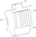
图1是本实用新型一实施例的医用吻合器的结构示意图;Fig. 1 is a schematic structural view of a medical stapler according to an embodiment of the present invention;
图2是本实用新型一实施例的钉头部摆头的示意图;Fig. 2 is a schematic diagram of a nail head swing head according to an embodiment of the present invention;
图3是本实用新型一实施例的摆头机构的结构示意图;Fig. 3 is a structural schematic diagram of a head swing mechanism according to an embodiment of the present invention;
图4是本实用新型一实施例的主动轮的结构示意图;Fig. 4 is a schematic structural view of a driving wheel according to an embodiment of the present invention;
图5是本实用新型一实施例的主动轮、从动轮和拉片驱动件配合的结构示意图;Fig. 5 is a schematic diagram of the structure of the cooperation of the driving wheel, the driven wheel and the pull-tab driver in an embodiment of the present invention;
图6是本实用新型一实施例的主动轮、从动轮和拉片驱动件配合的仰视图;Fig. 6 is a bottom view of the coordination of the driving wheel, the driven wheel and the pull tab driver in an embodiment of the present invention;
图7是本实用新型一实施例的去除第二壳体和主动轮后的摆头机构的结构示意图;Fig. 7 is a schematic structural view of the head swing mechanism after removing the second housing and the driving wheel according to an embodiment of the present invention;
图8是本实用新型一实施例的去除壳体和主动轮后的摆头机构的结构示意图;Fig. 8 is a structural schematic diagram of the swing head mechanism after removing the shell and the driving wheel according to an embodiment of the present invention;
图9是本实用新型一实施例的从动轮和拉片驱动件配合的示意图;Fig. 9 is a schematic diagram of the cooperation of the driven wheel and the pull piece driver in an embodiment of the present invention;
图10是本实用新型一实施例的拉片驱动件和摆头拉片配合的示意图;Fig. 10 is a schematic diagram of cooperation between the pull-tab driver and the swing-head pull-tab according to an embodiment of the present invention;
图11是本实用新型一实施例的拉片驱动件的结构示意图;Fig. 11 is a schematic structural view of a pull-tab driver according to an embodiment of the present invention;
图12是本实用新型一实施例的第一壳体的结构示意图;Fig. 12 is a schematic structural view of a first housing according to an embodiment of the present invention;
图13是本实用新型一实施例的支撑件的结构示意图;Fig. 13 is a schematic structural view of a support member according to an embodiment of the present invention;
图14是本实用新型一实施例的支撑架和主动轮配合的示意图。Fig. 14 is a schematic diagram of the cooperation between the support frame and the driving wheel according to an embodiment of the present invention.
附图标记:Reference signs:
11 吻合器本体 6 拉片驱动件11
111 套管 61 齿条部111 Bushing 61 Rack
112 固定把手 62 拉片配合部112
12 击发把手 63 第一引导件12 Firing handle 63 First guide
20 套管通道 64 第二引导件20
2 第二壳体(上壳体) 7 支撑件2 Second shell (upper shell) 7 Support piece
3 第一壳体(下壳体) 71 主动轮配合部3 First shell (lower shell) 71 Cooperating part of driving wheel
31 支撑件固定槽 72 从动轮支撑部31 Support
32 第二引导槽 721 通孔32
33 从动轮固定槽 73 止位部33 Fixed groove of driven
4 主动轮 731 第一引导面4
41 旋钮 732 第二引导面41
42 主动轮齿部 74 固定柱42
43 止位配合部 75 第一引导槽43
44 本体部 8 摆头拉片44
5 从动轮 9 钉头部5 Follower wheel 9 Nail head
51 第一从动轮齿部 91 钉砧51 First driven
52 第二从动轮齿部 92 钉仓组件52 Secondary driven
53 转轴部 93 连接件53
具体实施方式Detailed ways
现在将参考附图更全面地描述示例实施方式。然而,示例实施方式能够以多种形式实施,且不应被理解为限于在此阐述的实施方式;相反,提供这些实施方式使得本实用新型将全面和完整,并将示例实施方式的构思全面地传达给本领域的技术人员。在图中相同的附图标记表示相同或类似的结构,因而将省略对它们的重复描述。说明书中的“或”、“或者”均可能表示“和”或者“或”。虽然本说明书中可使用术语“上”、“下”、“之间”等来描述本实用新型的不同示例性特征和元件,但是这些术语用于本文中仅出于方便,例如根据附图中所述的示例的方向。在不同的实施例中,“上”和“下”的相对位置关系可以进行互换。本说明书中的任何内容都不应理解为需要结构的特定三维方向才落入本实用新型的范围内。本说明书中虽然采用“第一”或“第二”等来表示某些特征,但其仅为表示作用,而作为具体特征的数量和重要性的限制。Example embodiments will now be described more fully with reference to the accompanying drawings. Example embodiments may, however, be embodied in many forms and should not be construed as limited to the embodiments set forth herein; rather, these embodiments are provided so that this disclosure will be thorough and complete, and will fully incorporate the concepts of example embodiments. communicated to those skilled in the art. The same reference numerals denote the same or similar structures in the drawings, and thus their repeated descriptions will be omitted. "Or" and "or" in the specification may mean "and" or "or". Although the terms "upper," "lower," "between," etc. may be used in this specification to describe various exemplary features and elements of the present invention, these terms are used herein for convenience only, for example according to the Directions for the example described. In different embodiments, the relative positional relationship of "upper" and "lower" can be interchanged. Nothing in this specification should be construed as requiring a specific three-dimensional orientation of structures to fall within the scope of the present invention. Although "first" or "second" etc. are used to indicate certain features in this specification, they are only used for representational purposes, and serve as limitations on the quantity and importance of specific features.
本实用新型提供了一种摆头机构和包括该摆头机构的医用吻合器,所述医用吻合器包括钉头部、吻合器本体和设置于所述钉头部和所述吻合器本体之间的摆头机构。所述摆头机构包括主动轮、从动轮、拉片驱动件和摆头拉片。所述主动轮包括主动轮齿部。所述从动轮包括第一从动轮齿部和第二从动轮齿部,所述第一从动轮齿部与所述主动轮齿部相啮合。因此,在操作者控制主动轮旋转时,通过所述主动轮齿部和所述第一从动轮齿部的齿轮啮合,可以驱动所述从动轮旋转。同样地,如果直接控制从动轮旋转,也可以通过所述第一从动轮齿部和所述主动轮齿部的齿轮啮合,驱动所述主动轮旋转。The utility model provides a head swing mechanism and a medical stapler comprising the head swing mechanism. The medical stapler includes a nail head, a stapler body, and an swing head mechanism. The head swing mechanism includes a driving wheel, a driven wheel, a pull-tab driver and a swing pull-tab. The drive wheel includes a drive wheel tooth portion. The driven wheel includes a first driven wheel tooth portion and a second driven wheel tooth portion, and the first driven wheel tooth portion meshes with the driving wheel tooth portion. Therefore, when the operator controls the rotation of the driving wheel, the driven wheel can be driven to rotate through the gear meshing between the tooth portion of the driving wheel and the tooth portion of the first driven wheel. Similarly, if the driven wheel is directly controlled to rotate, the driving wheel may also be driven to rotate through the gear engagement between the teeth of the first driven wheel and the teeth of the driving wheel.
所述拉片驱动件包括拉片配合部和沿所述吻合器的轴向延伸的齿条部,所述齿条部与所述第二从动轮齿部相啮合。所述摆头拉片沿所述轴向延伸且固定于所述拉片配合部。所述拉片驱动件将所述从动轮的旋转运动转化为轴向运动。所述从动轮旋转时,所述第二从动轮齿部通过所述齿条部带动所述拉片驱动件沿所述吻合器的轴向运动,从而可以简单方便地实现吻合器的钉头部相对于吻合器本体的摆动。同时,本实用新型通过主动轮和从动轮的齿轮配合以及从动轮与齿条部的齿面配合,可以灵活地调整钉头部的摆动方向和摆动角度。The pull-tab driver includes a pull-tab matching portion and a rack portion extending axially of the stapler, the rack portion meshing with the tooth portion of the second driven wheel. The oscillating pull-tab extends along the axial direction and is fixed on the pull-tab matching portion. The tab driver converts the rotational motion of the driven wheel into axial motion. When the driven wheel rotates, the tooth part of the second driven wheel drives the pull tab driving part to move along the axial direction of the stapler through the rack part, so that the nail head of the stapler can be realized simply and conveniently. Swing relative to the stapler body. At the same time, the utility model can flexibly adjust the swing direction and swing angle of the nail head through the gear cooperation of the driving wheel and the driven wheel and the tooth surface cooperation of the driven wheel and the rack portion.
在本实用新型中,从动轮指的是设置有与拉片驱动件配合的第二从动轮齿部的齿轮,主动轮指的是与从动轮啮合配合的齿轮,但并不特指必须所述主动轮驱动从动轮旋转。在不同的实施例中,可以是所述主动轮旋转而驱动所述从动轮旋转,也可以是所述从动轮旋转而驱动所述主动轮旋转。In the present utility model, the driven wheel refers to the gear provided with the second driven wheel tooth part which cooperates with the pull piece driver, and the driving wheel refers to the gear meshed with the driven wheel, but it does not specifically refer to the The driving wheel drives the driven wheel to rotate. In different embodiments, the driving wheel may rotate to drive the driven wheel to rotate, or the driven wheel may rotate to drive the driving wheel to rotate.
下面结合附图详细介绍本实用新型各个具体实施例的摆头机构的结构,可以理解的是,各个具体实施例不作为本实用新型的保护范围的限制。The structure of the head swing mechanism of each specific embodiment of the present invention will be described in detail below in conjunction with the accompanying drawings. It should be understood that each specific embodiment is not intended to limit the scope of protection of the present invention.
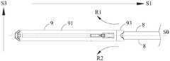
如图1~2所示,本实用新型提供了一种摆头机构和包括该摆头机构的医用吻合器,所述医用吻合器包括钉头部9、吻合器本体11、枢转地连接于所述吻合器本体11的击发把手12和设置于所述钉头部9和所述吻合器本体11之间的摆头机构。所述吻合器本体11包括本体壳体、固定把手112和套管111,所述套管111的远端侧连接于所述钉头部9。所述钉头部9包括相对设置的钉砧91和钉仓组件92以及位于所述钉砧91和钉仓组件92的近端侧的连接件93。所述摆头机构包括两个轴对称设置的摆头拉片8,所述摆头拉片8至少部分位于所述套管111的内部,图2中省去了套管111以示出所述摆头拉片8与钉头部9的配合。所述摆头拉片8的远端侧连接于所述连接件93。通过所述摆头拉片8的轴向运动可以控制所述钉头部9相对于吻合器的轴心S0进行横向摆动。具体地,在图2的视角中,位于上方的摆头拉片8向近端侧方向运动,位于下方的摆头拉片8向远端侧方向运动时,实现所述钉头部9沿R1方向摆动。位于上方的摆头拉片8向远端侧方向运动,位于下方的摆头拉片8向近端侧方向运动时,实现所述钉头部9沿R2方向摆动。As shown in Figures 1-2, the utility model provides a head swing mechanism and a medical stapler including the head swing mechanism, the medical stapler includes a nail head 9, a stapler body 11, and is pivotally connected to The firing handle 12 of the stapler body 11 and the head swing mechanism arranged between the nail head 9 and the stapler body 11 . The stapler body 11 includes a body shell, a fixed
在本实用新型中,远端侧和近端侧是相对于操作者来说的,距离操作者较近的一端为近端侧,距离操作者较远的一端,即更靠近手术位置的一端为远端侧,沿所述吻合器的轴心的方向为轴向,即从吻合器的远端侧到近端侧的方向,或从吻合器的近端侧到远端侧的方向。例如,在图2的视角中,所述钉头部9的远端侧为左边一侧,近端侧为右边一侧。S1方向即为从吻合器的远端侧向近端侧的方向。定义S1方向或与S1方向相反的方向为吻合器的轴向。定义图1中的S2方向为吻合器的纵向,即高度方向。定义图2中S3方向为吻合器的横向,即宽度方向。对于在本实用新型中,对于一个部件来说,内侧和外侧是相对于吻合器的轴心来说的,靠近轴心的一侧为内侧,远离轴心的一侧为外侧。In the present utility model, the distal side and the proximal side are relative to the operator, the end closer to the operator is the proximal side, and the end farther away from the operator, that is, the end closer to the operation position is The distal side, the direction along the axis of the stapler is the axial direction, that is, the direction from the distal side to the proximal side of the stapler, or the direction from the proximal side to the distal side of the stapler. For example, in the viewing angle of FIG. 2 , the distal side of the nail head 9 is the left side, and the proximal side is the right side. The S1 direction is the direction from the distal side to the proximal side of the stapler. Define the S1 direction or the direction opposite to the S1 direction as the axial direction of the stapler. Define the S2 direction in Figure 1 as the longitudinal direction of the stapler, that is, the height direction. Define the S3 direction in Figure 2 as the transverse direction of the stapler, that is, the width direction. In the present invention, for a component, the inside and outside are relative to the axis of the stapler, the side close to the axis is the inside, and the side away from the axis is the outside.
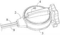
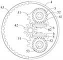
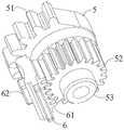
如图3~图7所示,所述摆头机构还包括壳体、主动轮4和从动轮5,所述主动轮4和所述从动轮5形成齿轮组。所述主动轮4和所述从动轮5被容纳于所述壳体的内部的容置腔体。所述拉片驱动件6也位于所述容置腔体之内。在图3的视角中,所述壳体包括位于下方的第一壳体3和位于上方的第二壳体2。所述第二壳体2和所述第一壳体3的内部共同限定一个容纳部分套管111的套管通道20。所述第一壳体3的内表面为所述壳体的第一内表面,所述第二壳体2的内表面为所述壳体的第二内表面。所述主动轮4包括旋钮41、本体部44和主动轮齿部42,所述本体部44包括远离所述从动轮5的第一侧和朝向所述从动轮5的第二侧,所述旋钮41设置于所述本体部44的第一侧,供操作者手持使用,所述主动轮齿部42设置于所述本体部44的第二侧,所述主动轮4和所述旋钮41的旋转中心同轴。所述主动轮齿部42的侧壁至少部分设置有第一齿面。所述从动轮5包括第一从动轮齿部52,所述第一从动轮齿部52的侧壁至少部分设置有第二齿面,所述第一齿面与所述第二齿面相啮合。因此,在操作者通过旋钮41控制主动轮4旋转时,通过所述第一齿面和所述第二齿面处的齿轮啮合,可以驱动所述从动轮5旋转。在另一实施例中,也可以是所述从动轮5包括一个旋钮,通过手动操作从动轮5驱动主动轮4旋转。如图5所示,在该实施例中,设置有两个所述从动轮5,两个所述从动轮5位于所述主动轮4的近端侧。对应地,设置有两个拉片驱动件6,两个摆头拉片沿轴向对称设置,各个从动轮5和各个拉片驱动件6分别与一个所述摆头拉片8配合。两个所述从动轮5分别位于所述吻合器的轴心的两侧,且轴对称对称设置,且两个所述从动轮5的轴心与所述主动轮4的轴心平行,两个所述从动轮5的轴心到所述主动轮4的轴心的距离相等。在该实施例中,所述第一从动轮齿部52的侧壁只有一部分设置有第二齿面,在另一实施方式中,也可以所述第一从动轮齿部52的侧壁整体均设置有第二齿面。或者,所述主动轮齿部42的侧壁只有部分设置有第一齿面。在另一实施方式中,两个从动轮5也可以不是轴对称设置的。例如,在图6的视图中,将上方的从动轮5设置在主动轮4的右上方,而将下方的从动轮5设置在主动轮4的左下方,或者,将上方的从动轮5设置在主动轮4的左上方,将下方的从动轮5设置在主动轮4的右下方等,均属于本实用新型的保护范围之内。As shown in FIGS. 3 to 7 , the swinging head mechanism further includes a housing, a
如图5~图9所示,所述摆头机构还包括拉片驱动件6。所述从动轮5还包括第二从动轮齿部52。在该实施例中,所述第一从动轮齿部51和第二从动轮齿部52同轴设置,由此,所述从动轮5的旋转中心是统一的,在摆头时更加稳定。所述第一从动轮齿部51和第二从动轮齿部52彼此固定设置,实现同步运动。在另一些实施方式中,所述第一从动轮齿部51和第二从动轮齿部52也可以是不同步转动的,例如在所述第一从动轮齿部51和第二从动轮齿部52之间另外增加传动齿轮/传动齿条等传动结构,或者将所述第一从动轮齿部51和第二从动轮齿部52采用其他方式组合在一起,或者从动轮的运动滞后于主动轮的运动。所述拉片驱动件6包括朝向所述摆头拉片8的第一侧和远离所述摆头拉片8的第二侧,所述拉片驱动件6的第一侧设置有所述拉片配合部62,所述拉片驱动件6的第二侧设置有齿条部61,该齿条部61沿所述吻合器的轴向延伸。通过所述第二从动轮齿部52与所述齿条部61的配合,可以将所述第二从动轮齿部52的旋转运动转化为所述齿条部61的轴向运动。在该实施例中,所述拉片配合部62为凸起部,所述摆头拉片8上设置有对应的孔或凹槽,实现所述拉片配合部62与所述摆头拉片8的固定连接。在另一实施方式中,也可以所述拉片配合部62为孔或凹槽,所述摆头拉片8上设置有与拉片配合部62相配合的凸起。因此,在操作者操作旋钮41旋转时,主动轮4的主动轮齿部42驱动从动轮5的第一从动轮齿部51旋转,第一从动轮齿部51带动第二从动轮齿部52旋转,进而带动所述齿条部61轴向运动,所述拉片驱动件6通过所述拉片配合部62带动所述摆头拉片8轴向运动,进而实现摆头效果。例如,在图6的视角中,操作者操作旋钮41旋转而使得主动轮4顺时针旋转时,两个从动轮5均逆时针旋转,上方的从动轮5带动上方的拉片驱动件6向近端侧方向运动,而下方的从动轮5带动下方的拉片驱动件6向远端侧方向运动,使得上方的摆头拉片8和下方的摆头拉片8(图6中未示出)分别向近端侧方向和远端侧方向运动,实现钉头部9向一侧摆动。同样地,操作者操作旋钮41旋转而使得主动轮4逆时针旋转时,两个从动轮5均顺时针旋转,上方的从动轮5带动上方的拉片驱动件6向远端侧方向运动,而下方的从动轮5带动下方的拉片驱动件6向近端侧方向运动,使得上方的摆头拉片8和下方的摆头拉片8(图6中未示出)分别向远端侧方向和近端侧方向运动,实现钉头部9向另一侧摆动。因此,该实施例中,可以简单方便地实现吻合器的钉头部9相对于吻合器本体的摆动。通过主动轮4和从动轮5的齿轮配合以及从动轮5与齿条部61的齿面配合,可以灵活地调整钉头部9的摆动方向和摆动角度。As shown in FIGS. 5 to 9 , the head swing mechanism further includes a pull-
如图7~12所示,所述摆头机构还包括支撑件7,固定设于所述壳体的容置腔体,并且将所述齿轮组固定于所述壳体。所述支撑件7包括朝向所述第一内表面的第三表面和朝向所述第二内表面的第四表面,在图7和图8的视角中,所述支撑件7的第三表面为下表面,第四表面为上表面。所述主动轮4和所述从动轮5至少部分设于所述第四表面和所述壳体的第二内表面之间,所述拉片驱动件6至少部分位于所述第三表面和所述壳体的第一内表面之间。如图7所示,所述支撑件7包括主动轮配合部71,所述主动轮配合部71与所述主动轮齿部42的中心形成嵌设配合,使得所述主动轮齿部42可绕所述主动轮配合部71旋转。在该实施例中,所述主动轮配合部71为一个凸柱,其嵌入所述主动轮齿部42中心的孔中。在另一实施例中,也可以所述主动轮配合部71为一个凹槽或孔,将主动轮齿部42的中心轴嵌入到该凹槽或孔中。As shown in FIGS. 7-12 , the head swing mechanism further includes a
结合图7、图8和图13可以看出,所述支撑件7包括从动轮配合部72,所述从动轮配合部72设置有通孔721,所述从动轮5穿设于所述通孔721中,以使得所述第一从动轮齿部51至少部分位于所述支撑件7的第四表面与所述壳体的第二内表面之间,所述第二从动轮齿部52至少部分位于所述支撑件7的第三表面与所述壳体的第一内表面之间。结合图8和图12可以看出,所述支撑件7的第三表面设置有多个固定柱74,所述第一壳体3的第一内表面设置有对应的多个支撑件固定槽31,所述固定柱74嵌设于所述支撑件固定槽31中,实现所述支撑件7与所述第一壳体3的固定。在另一种实施方式中,也可以所述支撑件7设置有多个固定槽,所述第一壳体3的第一内表面设置有固定柱,将固定柱嵌设于固定槽中。或者,所述支撑件7设置有固定槽和固定柱,所述第一壳体3设置有对应的固定柱和固定槽。7, 8 and 13, it can be seen that the
如图9和图12所示,在该实施例中,所述第一壳体3的第一内表面还设置有从动轮固定部,与所述从动轮5的转轴部53形成嵌设配合。在该实施例中,所述从动轮固定部为从动轮固定槽33,所述从动轮5的转轴部53嵌设于所述从动轮固定槽33中,且所述转轴部53可相对于所述第一壳体3旋转,从而保持摆头过程中所述从动轮5的稳定性。在另一实施方式中,也可以所述从动轮5的转轴部53设置有凹槽,所述第一壳体3的第一内表面设置有从动轮固定柱,嵌设于所述从动轮5的凹槽中。As shown in FIG. 9 and FIG. 12 , in this embodiment, the first inner surface of the
如图11和图13所示,在该实施例中,所述支撑件7上设置有第一引导部,所述拉片驱动件6设置有第二引导部,所述第一引导部为沿轴向延伸的第一引导槽75,所述第二引导部为第一引导件63,所述第一引导件63嵌设于所述第一引导槽75中,且所述第一引导件63的轴向长度小于所述第一引导槽75的轴向长度。通过所述第一引导槽75进一步限定所述拉片驱动件6的轴向运动方向。在另一种实施方式中,也可以所述第一引导部为第一引导件63,所述第二引导部为沿轴向延伸的第一引导槽75。如图11和图12所示,在该实施例中,所述壳体的第一内表面设置有第三引导部,所述拉片驱动件6设置有第四引导部,所述第三引导部为第二引导槽32,所述第四引导部为第二引导件64,所述第二引导件64嵌设于所述第二引导槽32中,且所述第二引导件64的轴向长度小于所述第二引导槽的轴向长度,进一步对所述第一引导槽75的轴向运动方向进行限定。在另一种实施方式中,也可以所述第三引导部为第二引导件64,所述第四引导部为第二引导槽32。As shown in Fig. 11 and Fig. 13, in this embodiment, the
现有的吻合器中,在钉头部摆动到一定角度后,摆头机构的稳定性不足,可能会引起钉头部角度的不稳定,影响操作者使用。基于此,该实施例进一步提供了止位部和止位配合部,来保持钉头部摆动后的稳定性,提升手术效果。In the existing stapler, after the nail head swings to a certain angle, the stability of the swing head mechanism is insufficient, which may cause the instability of the angle of the nail head and affect the use of the operator. Based on this, this embodiment further provides a stop part and a stop matching part to maintain the stability of the nail head after swinging and improve the surgical effect.
具体地,如图13和图14所示,在该实施例中,所述支撑件7上设置有止位部73,所述主动轮4设置有止位配合部43。所述主动轮4和/或所述从动轮5不受外力时,所述止位部73与所述止位配合部43相啮合,避免所述主动轮4和/或所述从动轮5意外发生转动,而影响所述摆头机构的稳定性。在需要进行摆头时,操作者通过旋钮41给所述主动轮4和/或所述从动轮5施加外力驱动,而使得所述主动轮4和/或所述从动轮5发生旋转时,所述止位部73在所述止位配合部43的作用下向远离所述止位配合部43的方向运动,而不阻挡所述主动轮4和/或所述从动轮5的旋转。如图13所示,所述止位部73的两侧分别设置有倾斜的第一引导面731和倾斜的第二引导面732。在摆头操作时,止位部73更容易与止位配合部43脱离,而不阻挡齿轮组的旋转,避免操作者摆头操作时受到很大阻力。Specifically, as shown in FIG. 13 and FIG. 14 , in this embodiment, the
在该实施例中,所述主动轮齿部42设置于所述本体部的第二侧的边缘位置,所述止位配合部43与所述主动轮齿部42分离设置,且所述止位配合部43的表面为圆弧形齿面。所述止位部73设置于所述支撑件7的远端侧。所述止位部73至少部分是弹性的,所述主动轮4和/或所述从动轮5受外力驱动发生旋转时,所述止位部73在所述止位配合部43的作用下向远离所述止位配合部43的方向运动,且发生弹性变形。所述主动轮4和/或所述从动轮5上的外力消失后,所述止位部73在弹性变形恢复力的作用下,可以返回至初始位置,再次与所述止位配合部43啮合。由此,在摆头操作完成后,吻合器的使用过程中,钉头部9可以保持在一个稳定的角度,而不会出现不可控的摇摆现象,有利于提升手术效果。如图6所示,所述止位配合部43均匀地连续设置的至少两个止位配合部43,所述各个止位配合部43分别位于所述吻合器轴心的左右两侧;初始位置时,所述止位部73啮合于位于轴心处的所述止位配合部43,所述吻合器头部与轴向呈“0”度的角度,当顺时针或者逆时针方向旋转旋钮41时,所述止位部73分别可以和各个所述止位配合部43啮合,停留在不同的角度。In this embodiment, the drive
在另一可替代的实施方式中,所述止位部也可以设置在壳体上,即设置在所述第一壳体3或第二壳体2上。所述止位配合部也可以设置在其他位置。例如,所述止位配合部设置在所述本体部的第二侧的其他位置而非边缘。或者,所述止位配合部也可以为所述主动轮齿部42。所述止位部可以设置在所述壳体或所述支撑件7的靠近主动轮齿部42的位置。在所述主动轮4和/或从动轮5不受外力时,所述止位部和所述主动轮齿部42相啮合,阻挡所述主动轮4的意外转动。或者,所述止位配合部也可以为所述第一从动轮齿部51。所述止位部也可以设置在所述壳体或所述支撑件7的靠近第一从动轮齿部51的位置。即在所述主动轮4和/或从动轮5不受外力时,所述止位部和所述第一从动轮齿部51相啮合,阻挡所述从动轮5的意外转动。或者,所述止位配合部也可以为所述第二从动轮齿部52,所述止位部设置在所述壳体或所述支撑件7的靠近第二从动轮齿部52的位置。即在所述主动轮4和/或从动轮5不受外力时,所述止位部和所述第二从动轮齿部52相啮合,阻挡所述从动轮5的意外转动。In another alternative embodiment, the stop portion can also be arranged on the casing, that is, on the
以上内容是结合具体的优选实施方式对本实用新型所作的进一步详细说明,不能认定本实用新型的具体实施只局限于这些说明。对于本实用新型所属技术领域的普通技术人员来说,在不脱离本实用新型构思的前提下,还可以做出若干简单推演或替换,都应当视为属于本实用新型的保护范围。The above content is a further detailed description of the utility model in combination with specific preferred embodiments, and it cannot be assumed that the specific implementation of the utility model is only limited to these descriptions. For a person of ordinary skill in the technical field to which the utility model belongs, without departing from the concept of the utility model, some simple deduction or substitutions can also be made, which should be regarded as belonging to the protection scope of the utility model.
Claims (20)
Priority Applications (1)
| Application Number | Priority Date | Filing Date | Title |
|---|---|---|---|
| CN202220973110.6UCN217853128U (en) | 2022-04-25 | 2022-04-25 | Head swinging mechanism and medical stapler |
Applications Claiming Priority (1)
| Application Number | Priority Date | Filing Date | Title |
|---|---|---|---|
| CN202220973110.6UCN217853128U (en) | 2022-04-25 | 2022-04-25 | Head swinging mechanism and medical stapler |
Publications (1)
| Publication Number | Publication Date |
|---|---|
| CN217853128Utrue CN217853128U (en) | 2022-11-22 |
Family
ID=84087958
Family Applications (1)
| Application Number | Title | Priority Date | Filing Date |
|---|---|---|---|
| CN202220973110.6UActiveCN217853128U (en) | 2022-04-25 | 2022-04-25 | Head swinging mechanism and medical stapler |
Country Status (1)
| Country | Link |
|---|---|
| CN (1) | CN217853128U (en) |
Cited By (2)
| Publication number | Priority date | Publication date | Assignee | Title |
|---|---|---|---|---|
| CN116983038A (en)* | 2022-04-25 | 2023-11-03 | 天臣国际医疗科技股份有限公司 | Swing mechanism and medical anastomat |
| CN118415702A (en)* | 2024-05-11 | 2024-08-02 | 江苏博朗森思医疗器械有限公司 | Electric stapler |
- 2022
- 2022-04-25CNCN202220973110.6Upatent/CN217853128U/enactiveActive
Cited By (2)
| Publication number | Priority date | Publication date | Assignee | Title |
|---|---|---|---|---|
| CN116983038A (en)* | 2022-04-25 | 2023-11-03 | 天臣国际医疗科技股份有限公司 | Swing mechanism and medical anastomat |
| CN118415702A (en)* | 2024-05-11 | 2024-08-02 | 江苏博朗森思医疗器械有限公司 | Electric stapler |
Similar Documents
| Publication | Publication Date | Title |
|---|---|---|
| CN217853128U (en) | Head swinging mechanism and medical stapler | |
| EP4356845A1 (en) | Instrument drive transmission mechanism and assembly mechanism of surgical robot | |
| EP1508306B1 (en) | Surgical instrument incorporating an articulation mechanism having rotation about the longitudinal axis | |
| CN219207115U (en) | Swing mechanism and surgical anastomat | |
| WO2024109301A1 (en) | Stapler available for manual operation upon failure of electric mode | |
| WO2023143313A1 (en) | Surgical instrument | |
| CN217960199U (en) | Firing mechanism and medical anastomat | |
| CN211704727U (en) | Steering self-locking device of endoscope anastomat and endoscope anastomat | |
| CN216854748U (en) | Swing head mechanism and medical stapler | |
| WO2024109714A1 (en) | Emergency apparatus and surgical instrument | |
| CN112754569A (en) | Electric endoscope anastomat with reset function | |
| CN216854747U (en) | Swing head mechanism and medical stapler | |
| CN116407187A (en) | Jaw assembly driving device for surgical instrument and surgical instrument | |
| CN115568896B (en) | Medical stapler containing misaligned teeth | |
| CN118892340A (en) | A driving locking structure for surgical instruments and surgical instruments | |
| CN216854749U (en) | Head swinging mechanism and medical anastomat | |
| CN116983038A (en) | Swing mechanism and medical anastomat | |
| CN211723295U (en) | Anastomat end effector, deflection device thereof and anastomat adopting deflection device | |
| CN217286061U (en) | Quick aligning mechanism of surgical instrument box and power box | |
| CN115778556A (en) | Transmission mechanism for surgical instrument, surgical instrument and surgical robot | |
| CN112490755B (en) | A docking device and end drive mechanism | |
| CN117159150A (en) | Laparoscopic surgical instrument and surgical robot | |
| CN208838055U (en) | Stapler Rotation Actuator and Stapler | |
| CN116269804A (en) | Surgical Instruments and Surgical Robots | |
| CN116138825A (en) | Swing head mechanism and medical stapler |
Legal Events
| Date | Code | Title | Description |
|---|---|---|---|
| GR01 | Patent grant | ||
| GR01 | Patent grant |