Movatterモバイル変換


[0]ホーム

URL:


CN217822482U - Fingerprint key component and terminal equipment - Google Patents

Fingerprint key component and terminal equipment
Download PDF

Info

Publication number
CN217822482U
CN217822482UCN202221815672.4UCN202221815672UCN217822482UCN 217822482 UCN217822482 UCN 217822482UCN 202221815672 UCN202221815672 UCN 202221815672UCN 217822482 UCN217822482 UCN 217822482U
Authority
CN
China
Prior art keywords
fingerprint
button
magnetic
positioning
key
Prior art date
Legal status (The legal status is an assumption and is not a legal conclusion. Google has not performed a legal analysis and makes no representation as to the accuracy of the status listed.)
Active
Application number
CN202221815672.4U
Other languages
Chinese (zh)
Inventor
温晓雷
余传芳
张全涛
Current Assignee (The listed assignees may be inaccurate. Google has not performed a legal analysis and makes no representation or warranty as to the accuracy of the list.)
Beijing Xiaomi Mobile Software Co Ltd
Original Assignee
Beijing Xiaomi Mobile Software Co Ltd
Priority date (The priority date is an assumption and is not a legal conclusion. Google has not performed a legal analysis and makes no representation as to the accuracy of the date listed.)
Filing date
Publication date
Application filed by Beijing Xiaomi Mobile Software Co LtdfiledCriticalBeijing Xiaomi Mobile Software Co Ltd
Priority to CN202221815672.4UpriorityCriticalpatent/CN217822482U/en
Application grantedgrantedCritical
Publication of CN217822482UpublicationCriticalpatent/CN217822482U/en
Activelegal-statusCriticalCurrent
Anticipated expirationlegal-statusCritical

Links

Images

Landscapes

Abstract

The utility model discloses a fingerprint key component and terminal equipment, the fingerprint key component comprises a key component, a fixing component and a force application component, the fixing component is suitable for being matched with the key component; the force application assembly is arranged on at least one of the key support and the fixing piece so as to provide a holding force back to the gravity direction for the key assembly. The utility model discloses fingerprint key part utilizes the application of force subassembly of establishing on at least one of button subassembly and mounting to provide the confining force of gravity direction dorsad to the button subassembly, avoids the slope phenomenon that the button subassembly leads to because of the action of gravity to not only can avoid the user to press the time upper and lower end hand sense inconsistent, can improve fingerprint key part's outward appearance delicacy degree in addition, improve user experience.

Description

Translated fromChinese
指纹按键部件和终端设备Fingerprint key components and terminal equipment

技术领域technical field

本实用新型涉及电子设备技术领域,具体涉及一种指纹按键部件和终端设备。The utility model relates to the technical field of electronic equipment, in particular to a fingerprint button part and terminal equipment.

背景技术Background technique

目前,电子设备,例如智能手机多采用侧指纹解锁方式,即将指纹按键部件安装在中框侧边的指纹槽内。相关技术中,指纹按键部件包括指纹模组和switch键(开关键),指纹模组和开关键相连并安装在指纹槽内,指纹槽内具有止抵部,开关键止抵于止抵部上。由于指纹模组和开关键的加工以及装配公差的存在,开关键与止抵部之间可能存在虚接触甚至间隙,导致指纹模组和开关键在重力作用下发生朝向电池盖方向的倾斜,影响指纹按键部件的手感和外观精致度,影响用户体验。At present, electronic devices, such as smart phones, mostly adopt a side fingerprint unlocking method, that is, a fingerprint button component is installed in a fingerprint slot on the side of the middle frame. In the related art, the fingerprint button part includes a fingerprint module and a switch key (switch key), the fingerprint module is connected to the switch key and installed in the fingerprint groove, and there is a stop part in the fingerprint groove, and the switch key stops on the stop part . Due to the processing and assembly tolerances of the fingerprint module and the switch key, there may be a virtual contact or even a gap between the switch key and the stopper, causing the fingerprint module and the switch key to tilt towards the battery cover under the action of gravity, affecting The touch and appearance of the fingerprint button components affect the user experience.

实用新型内容Utility model content

本实用新型旨在至少在一定程度上解决相关技术中的技术问题之一。The utility model aims to solve one of the technical problems in the related art at least to a certain extent.

为此,本实用新型的实施例提出一种指纹按键部件,以提高指纹按键部件按压手感好和外观精致度。For this reason, the embodiment of the present utility model proposes a fingerprint button component, so as to improve the pressing feeling and the exquisite appearance of the fingerprint button component.

本实用新型的实施例还提出一种具有上述指纹按键部件的终端设备。Embodiments of the present utility model also propose a terminal device having the above-mentioned fingerprint button component.

本实用新型实施例的指纹按键部件包括按键组件、固定件和施力组件,所述固定件适于与所述按键组件配合;所述施力组件设于所述按键组件和所述固定件中的至少一者上,以对所述按键支架提供背向重力方向的保持力。The fingerprint button part of the embodiment of the utility model includes a button assembly, a fixing part and a force applying component, and the fixing part is suitable for cooperating with the button assembly; the force applying component is arranged in the button component and the fixing part At least one of them, so as to provide a holding force against the direction of gravity for the key bracket.

本实用新型实施例的指纹按键部件,当指纹按键部件安装在终端设备的指纹槽内使用时,利用设在按键组件和固定件的至少一者上的施力组件对按键组件提供背向重力方向的保持力,避免按键组件因重力作用导致的倾斜现象,从而不仅可以避免用户按压时上下端手感不一致,而且可以提高指纹按键部件的外观精致度,提高用户体验。The fingerprint button part of the embodiment of the utility model, when the fingerprint button part is installed in the fingerprint slot of the terminal device and used, utilizes the force applying component provided on at least one of the button component and the fixing part to provide the key component with a back-to-gravity direction. It can avoid the inclination phenomenon of the button assembly caused by gravity, so as to not only avoid the inconsistency of the upper and lower ends when the user presses it, but also improve the appearance of the fingerprint button assembly and improve the user experience.

在一些实施例中,所述施力组件包括至少一个磁性件。In some embodiments, the force applying assembly includes at least one magnetic member.

在一些实施例中,所述施力组件包括多个磁性件,多个所述磁性件至少包括第一磁性件以及第二磁性件,所述第一磁性件设于所述按键组件,所述第二磁性件设于所述固定件,所述第一磁性件与所述第二磁性件配合以对所述按键组件提供背向重力方向的保持力。In some embodiments, the force application component includes a plurality of magnetic parts, and the plurality of magnetic parts at least include a first magnetic part and a second magnetic part, the first magnetic part is arranged on the button assembly, and the The second magnetic part is arranged on the fixing part, and the first magnetic part cooperates with the second magnetic part to provide a holding force for the key assembly against the direction of gravity.

在一些实施例中,所述第一磁性件和所述第二磁性件均具有N极和S极,所述第一磁性件和所述第二磁性件的极性相同的磁极沿第一方向相对设置,所述第一磁性件的N极至所述第二磁性件的N极的方向与所述重力方向一致。In some embodiments, both the first magnetic part and the second magnetic part have an N pole and an S pole, and the magnetic poles of the first magnetic part and the second magnetic part have the same polarity along the first direction Relatively disposed, the direction from the N pole of the first magnetic member to the N pole of the second magnetic member is consistent with the direction of gravity.

在一些实施例中,所述按键组件具有第一安装槽,所述第一磁性件设在所述第一安装槽内;和/或所述固定件具有第二安装槽,所述第二磁性件设在所述第二安装槽内。In some embodiments, the button assembly has a first installation groove, and the first magnetic member is arranged in the first installation groove; and/or the fixing member has a second installation groove, and the second magnetic member The parts are arranged in the second installation groove.

在一些实施例中,所述固定件包括第一连接部和第二连接部,所述第一连接部沿第二方向延伸,所述第一连接部在所述第一方向上设于所述按键组件的一侧;所述第二连接部设于所述第一连接部,所述第二磁性件设于所述第二连接部。In some embodiments, the fixing member includes a first connecting portion and a second connecting portion, the first connecting portion extends along a second direction, and the first connecting portion is disposed on the first connecting portion in the first direction. One side of the button assembly; the second connecting part is arranged on the first connecting part, and the second magnetic part is arranged on the second connecting part.

在一些实施例中,所述第一连接部具有供紧固件穿过的连接孔;和/或所述固定件还包括沿所述第一方向延伸的第一定位部,所述按键组件具有第二定位部,所述第一定位部与所述第二定位部配合。In some embodiments, the first connecting portion has a connecting hole through which a fastener passes; and/or the fixing member further includes a first positioning portion extending along the first direction, and the button assembly has The second positioning part, the first positioning part cooperates with the second positioning part.

在一些实施例中,所述第二定位部和所述第一定位部的数量均为多个,多个所述第一定位部沿所述第二方向间隔设于所述第一连接部,多个所述第一定位部与多个所述第二定位部一一对应,每个所述第一定位部与对应的所述第二定位部配合。In some embodiments, the number of the second positioning part and the number of the first positioning part are multiple, and the plurality of the first positioning parts are arranged at intervals along the second direction on the first connecting part, A plurality of the first positioning parts correspond to a plurality of the second positioning parts one by one, and each of the first positioning parts cooperates with the corresponding second positioning part.

在一些实施例中,所述第二连接部和多个所述第一定位部在第三方向上位于所述第一连接部的同一侧,其中,所述第三方向垂直于所述第二方向。In some embodiments, the second connecting portion and the plurality of first positioning portions are located on the same side of the first connecting portion in a third direction, wherein the third direction is perpendicular to the second direction .

在一些实施例中,所述第二连接部设于相邻两个所述第一定位部之间;和/或所述第一磁性件设于相邻两个所述第二定位部之间。In some embodiments, the second connection part is arranged between two adjacent first positioning parts; and/or the first magnetic part is arranged between two adjacent second positioning parts .

在一些实施例中,按键组件包括按键支架、指纹模组和开关键,所述第一磁性件设于所述按键支架,所述指纹模组和所述开关键均与所述按键支架相连。In some embodiments, the button assembly includes a button bracket, a fingerprint module and a switch key, the first magnetic member is arranged on the button bracket, and both the fingerprint module and the switch key are connected to the button bracket.

在一些实施例中,所述指纹按键部件还包括支撑组件,所述支撑组件包括第三连接部和多个支撑部,所述第三连接部沿所述第二方向延伸;多个所述支撑部沿所述第二方向间隔设于所述第三连接部,多个所述支撑部与多个所述开关键一一对应,每个所述开关键背向所述指纹模组的一侧用于止抵于对应的所述支撑部。In some embodiments, the fingerprint button part further includes a support assembly, the support assembly includes a third connection part and a plurality of support parts, the third connection part extends along the second direction; a plurality of the support parts The supporting parts are arranged on the third connecting part at intervals along the second direction, and a plurality of the supporting parts correspond to a plurality of the switch keys one by one, and each of the switch keys faces away from the side of the fingerprint module Used to stop against the corresponding support portion.

在一些实施例中,所述开关键的数量为多个,多个所述开关键均与所述按键支架相连;所述支撑组件还包括多个弹性支撑件,所述弹性支撑件具有所述支撑部,多个所述弹性支撑件与多个所述开关键一一对应,每个所述弹性支撑件的所述支撑部朝向对应的所述开关键设置,每个所述开关键用于止抵于对应的所述弹性支撑件的所述支撑部。In some embodiments, the number of the switch keys is multiple, and the multiple switch keys are all connected to the key bracket; the support assembly also includes a plurality of elastic supports, and the elastic supports have the A support part, a plurality of the elastic supports correspond to a plurality of the switch keys one by one, the support part of each elastic support is arranged toward the corresponding switch key, and each switch key is used for stop against the supporting portion of the corresponding elastic supporting member.

在一些实施例中,多个所述开关键沿第二方向间隔设置,所述指纹模组和所述开关键在第三方向上分别位于所述按键支架的相对两侧,其中,所述第二方向垂直于所述重力方向,所述第三方向垂直于所述第二方向和所述重力方向。In some embodiments, a plurality of the switch keys are arranged at intervals along the second direction, and the fingerprint module and the switch keys are respectively located on opposite sides of the key bracket in the third direction, wherein the second The direction is perpendicular to the direction of gravity, and the third direction is perpendicular to the second direction and the direction of gravity.

在一些实施例中,所述第三连接部具有避让槽,所述避让槽设于相邻两个所述支撑部之间。In some embodiments, the third connecting portion has an avoidance groove, and the avoidance groove is provided between two adjacent support portions.

在一些实施例中,所述指纹按键部件还包括电路板,所述电路板包括相连的第一部分、第二部分和第三部分,所述第一部分与所述指纹模组电连接,所述第二部分与所述开关键电连接,所述第三部分用于与主板电连接。In some embodiments, the fingerprint button component further includes a circuit board, and the circuit board includes a connected first part, a second part and a third part, the first part is electrically connected to the fingerprint module, and the second part is electrically connected to the fingerprint module. The second part is electrically connected with the switch key, and the third part is used for electrical connection with the main board.

在一些实施例中,所述第二部分沿所述第二方向延伸,所述第三部分与所述第二部分电连接的一端在所述第二方向上位于相邻两个所述开关键之间。In some embodiments, the second portion extends along the second direction, and one end of the third portion electrically connected to the second portion is located between two adjacent switch keys in the second direction. between.

在一些实施例中,所述第一部分沿所述第二方向延伸,所述电路板还包括过渡部分,所述过渡部分沿第三方向延伸,所述过渡部分的一端与所述第一部分相连,所述过渡部分的另一端与所述第二部分相连,所述第一部分、所述第二部分和所述过渡部分中的至少一者与所述按键支架相连。In some embodiments, the first portion extends along the second direction, the circuit board further includes a transition portion extending along the third direction, one end of the transition portion is connected to the first portion, The other end of the transition part is connected to the second part, and at least one of the first part, the second part and the transition part is connected to the key holder.

在一些实施例中,所述按键支架具有沿所述第三方向延伸的第二定位柱,所述第二部分具有第二定位孔,所述第二定位柱插装在所述第二定位孔内。In some embodiments, the key bracket has a second positioning column extending along the third direction, the second part has a second positioning hole, and the second positioning column is inserted into the second positioning hole Inside.

本实用新型实施例的终端设备包括中框和指纹按键部件,所述中框的侧边设有指纹槽,所述中框具有与所述指纹槽连通的第一开口;所述指纹按键部件为上述任一实施例所述的指纹按键部件,所述指纹按键部件设于所述指纹槽,所述指纹模组的至少一部分通过所述第一开口凸出所述中框的侧边。The terminal device in the embodiment of the present invention includes a middle frame and a fingerprint button part, the side of the middle frame is provided with a fingerprint groove, and the middle frame has a first opening communicating with the fingerprint groove; the fingerprint button part is As for the fingerprint button part according to any one of the above embodiments, the fingerprint button part is arranged in the fingerprint slot, and at least a part of the fingerprint module protrudes from the side of the middle frame through the first opening.

在一些实施例中,所述中框还具有与所述指纹槽连通的第二开口,所述第二开口和所述第一开口设于所述中框的不同侧,所述固定件与所述中框相连,所述固定件封堵所述第二开口的至少一部分。In some embodiments, the middle frame further has a second opening communicating with the fingerprint groove, the second opening and the first opening are arranged on different sides of the middle frame, the fixing part and the The middle frame is connected, and the fixing member blocks at least a part of the second opening.

附图说明Description of drawings

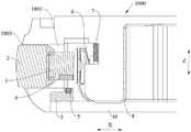
图1是本实用新型一个实施例的指纹按键部件的结构示意图(隐去了弹性支撑件)。Fig. 1 is a schematic structural view of a fingerprint button component according to an embodiment of the present invention (the elastic support is hidden).

图2是图1隐去固定件的结构示意图。Fig. 2 is a schematic structural view of Fig. 1 with the fixing part hidden.

图3是图1中固定件的结构示意图。Fig. 3 is a schematic structural diagram of the fixing part in Fig. 1 .

图4是本实用新型一个实施例的终端设备的局部结构示意图。Fig. 4 is a schematic diagram of a partial structure of a terminal device according to an embodiment of the present invention.

图5是图4中固定件与中框连接前的结构示意图。Fig. 5 is a structural schematic view before the fixing member is connected with the middle frame in Fig. 4 .

图6是图4的剖视图。FIG. 6 is a sectional view of FIG. 4 .

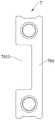
图7是图4中支撑组件的结构示意图。Fig. 7 is a schematic structural diagram of the support assembly in Fig. 4 .

图8是图4中支撑组件的另一视角的结构示意图。FIG. 8 is a structural schematic diagram of another viewing angle of the support assembly in FIG. 4 .

附图标记:Reference signs:

指纹按键部件100;Fingerprint button part 100;

按键支架1;第一安装槽101;第二定位部102;第二定位柱103;Key bracket 1;first installation groove 101;second positioning part 102;second positioning column 103;

指纹模组2;Fingerprint module 2;

固定件3;第一连接部301;连接孔3011;第一定位部302;第二连接部303;第二安装槽3031;Thefixing part 3; the first connectingpart 301; the connectinghole 3011; thefirst positioning part 302; the second connectingpart 303; thesecond installation groove 3031;

第一磁性件4;The first magnetic part 4;

第二磁性件5;The secondmagnetic part 5;

开关键6;switch key 6;

支撑组件7;第三连接部701;避让槽7011;支撑部702;Support assembly 7; third connectingpart 701;escape groove 7011; supportingpart 702;

电路板8;第一部分801;第二部分802;第三部分803;第二定位孔804;过渡部分805;Circuit board 8;first part 801;second part 802;third part 803;second positioning hole 804;transition part 805;

终端设备1000;terminal equipment 1000;

中框10;指纹槽1001;第一开口1002;第二开口1003。Middle frame 10 ;fingerprint groove 1001 ;first opening 1002 ;second opening 1003 .

具体实施方式Detailed ways

下面详细描述本实用新型的实施例,所述实施例的示例在附图中示出。下面通过参考附图描述的实施例是示例性的,旨在用于解释本实用新型,而不能理解为对本实用新型的限制。Embodiments of the invention are described in detail below, examples of which are illustrated in the accompanying drawings. The embodiments described below by referring to the figures are exemplary and are intended to explain the present invention, but should not be construed as limiting the present invention.

相关技术中,指纹按键部件安装在终端设备的边框的侧边上,实现侧指纹解锁。指纹按键部件中的指纹模组和开关键集成在一起,利于指纹按键部件的小型化设计,且方便指纹按键部件安装在边框的指纹槽内,且开关键止抵在指纹槽内的止抵部上。由于加工和装配公差,指纹按键部件安装在指纹槽内后,开关键与指纹槽内的止抵部之间容易存在虚接触甚至间隙,在指纹模组和开关键的重力作用下,指纹模组和开关键组成的整体容易在重力作用下发生第一方向的倾斜现象(指纹模组和开关键组成的整体一端高一端低),进而不仅导致用户按压指纹模组时上下端的手感不一致,而且导致指纹按键部件的外观较差。In the related art, the fingerprint button part is installed on the side of the frame of the terminal device to realize side fingerprint unlocking. The fingerprint module and the switch key in the fingerprint button part are integrated together, which is beneficial to the miniaturization design of the fingerprint button part, and facilitates the installation of the fingerprint button part in the fingerprint groove of the frame, and the switch key stops at the stop part in the fingerprint groove superior. Due to processing and assembly tolerances, after the fingerprint key components are installed in the fingerprint groove, there is likely to be a virtual contact or even a gap between the switch key and the stopper in the fingerprint groove. Under the gravity of the fingerprint module and the switch key, the fingerprint module The whole composed of the switch key is prone to tilt in the first direction under the action of gravity (the fingerprint module and the switch key are composed of one end high and the other end low), which not only leads to inconsistencies between the upper and lower ends when the user presses the fingerprint module, but also leads to The appearance of the fingerprint button part is poor.

如图1至图8所示,本实用新型实施例的指纹按键部件100包括按键组件、固定件3和施力组件,固定件3适于与按键组件配合。施力组件设于按键组件和固定件3中的至少一者上,以对按键组件提供背向重力方向的保持力。As shown in FIG. 1 to FIG. 8 , thefingerprint button component 100 of the embodiment of the present invention includes a button assembly, a fixingmember 3 and a force applying assembly, and the fixingmember 3 is suitable for cooperating with the button assembly. The force applying component is arranged on at least one of the key component and the fixingmember 3, so as to provide the key component with a holding force against the direction of gravity.

固定件3适于与按键组件配合,可以理解为:固定件3与按键组件相连;或者,固定件3与按键组件不相连,但是固定件3和按键组件的安装位置相关联,例如,固定件3设在按键组件的一侧。The fixingpart 3 is suitable for matching with the button assembly, which can be understood as: the fixingpart 3 is connected with the button assembly; or, the fixingpart 3 is not connected with the button assembly, but the fixingpart 3 is associated with the installation position of the button assembly, for example, the fixingpart 3 is located on one side of the button assembly.

本实用新型实施例的指纹按键部件100,当指纹按键部件100安装在终端设备1000的指纹槽1001内使用时,利用设在按键组件和固定件3的至少一者上的施力组件对按键组件提供背向重力方向的保持力,使得利用施力组件可以对按键组件提供背向重力方向的保持力,避免按键组件因重力作用导致的倾斜现象,从而不仅可以避免用户按压时上下端手感不一致,而且可以提高指纹按键部件100的外观精致度,提高用户体验。The fingerprintkey component 100 of the embodiment of the present utility model, when the fingerprintkey component 100 is installed in thefingerprint slot 1001 of theterminal device 1000 and used, utilizes the force applying component located on at least one of the key component and the fixingmember 3 to press the key component. Provide a holding force against the direction of gravity, so that the force applying component can provide a holding force against the direction of gravity for the key component, avoiding the tilting phenomenon of the key component due to gravity, so as to not only avoid the inconsistency of the upper and lower ends when the user presses, Moreover, the appearance refinement of thefingerprint button part 100 can be improved, and the user experience can be improved.

因此,本实用新型实施例的指纹按键部件100具有按压手感好和外观精致度高等优点。Therefore, thefingerprint button component 100 of the embodiment of the present invention has the advantages of good pressing feel and high appearance.

按键组件包括按键支架1、指纹模组2和开关键6,指纹模组2和开关键6均与按键支架1相连。The button assembly includes abutton bracket 1 , afingerprint module 2 and aswitch key 6 , and both thefingerprint module 2 and theswitch key 6 are connected to thebutton bracket 1 .

可选地,指纹模组2包括传感器和封装材料,指纹模组2为LGA(Land Grid Array,栅格阵列封装)。Optionally, thefingerprint module 2 includes a sensor and packaging materials, and thefingerprint module 2 is LGA (Land Grid Array, grid array package).

可选地,施力组件包括至少一个磁性件。Optionally, the force applying component includes at least one magnetic piece.

例如,施力组件包括一个磁性件,磁性件设在按键支架1上,固定件3为导磁件,设在按键支架1上的磁性件与固定件3之间产生吸力,该吸力形成上述保持力。For example, the force application assembly includes a magnetic piece, the magnetic piece is arranged on thebutton bracket 1, and the fixingpiece 3 is a magnetically conductive piece, and an attraction force is generated between the magnetic piece on thebutton bracket 1 and the fixingpiece 3, and the above-mentioned holding force is formed by the suction force. force.

通过将施力组件设为包括至少一个磁性件,利用磁性件对按键支架1提供背向重力方向的保持力,磁性件只需要与按键支架1和固定件3中的一者固定连接即可,而不需要同时与按键支架1和固定件3固定连接。由此,可以简化施力组件的安装工序,方便施力组件的安装,从而有利于指纹按键部件100的组装以及方便指纹按键部件100安装在终端设备1000的边框10上。By setting the force application assembly to include at least one magnetic piece, the magnetic piece is used to provide a holding force against the direction of gravity for thekey support 1, and the magnetic piece only needs to be fixedly connected to one of thekey support 1 and the fixingpiece 3, It is not necessary to be fixedly connected to thekey bracket 1 and the fixingmember 3 at the same time. Thus, the installation process of the force applying component can be simplified and the installation of the force applying component can be facilitated, thereby facilitating the assembly of the fingerprintkey component 100 and the installation of the fingerprintkey component 100 on theframe 10 of theterminal device 1000 .

当然,在另一些实施例中,施力组件也可以为非磁性件。例如,施力组件为弹簧,弹簧的一端与按键支架1相连,弹簧的另一端与固定件3相连,利用弹簧对按键支架1提供背向重力方向的保持力。Of course, in some other embodiments, the force applying component can also be a non-magnetic component. For example, the force application component is a spring, one end of the spring is connected to thebutton bracket 1 , and the other end of the spring is connected to the fixingmember 3 , and the spring is used to provide a holding force against the direction of gravity for thebutton bracket 1 .

可选地,施力组件包括多个磁性件,多个磁性件至少包括第一磁性件4和第二磁性件 5。换言之,施力组件包括多个磁性件,多个磁性件中的一部分为第一磁性件4,多个磁性件中的另一部分为第二磁性件5。Optionally, the force applying assembly includes a plurality of magnetic pieces, and the multiple magnetic pieces include at least a first magnetic piece 4 and a secondmagnetic piece 5. In other words, the force applying assembly includes a plurality of magnetic parts, a part of the plurality of magnetic parts is the first magnetic part 4 , and another part of the plurality of magnetic parts is the secondmagnetic part 5 .

第一磁性件4设于按键组件,第二磁性件5设于固定件3,第一磁性件4与第二磁性件5配合以对按键组件提供背向重力方向的保持力。The first magnetic part 4 is arranged on the key assembly, and the secondmagnetic part 5 is arranged on the fixingpart 3 . The first magnetic part 4 and the secondmagnetic part 5 cooperate to provide a holding force for the key assembly against the direction of gravity.

例如,如图2和图5所示,施力组件包括两个磁性件,两个磁性件中的一者为第一磁性件4。两个磁性件中的另一者为第二磁性件5,第一磁性件4与按键支架1固定连接,第二磁性件5与固定件3固定连接,第一磁性件4和第二磁性件5沿第一方向相对设置。由此,利用第一磁性件4和第二磁性件5之间的磁力,对按键组件提供背向重力方向的保持力。For example, as shown in FIG. 2 and FIG. 5 , the force applying assembly includes two magnetic parts, one of which is the first magnetic part 4 . The other of the two magnetic parts is the secondmagnetic part 5, the first magnetic part 4 is fixedly connected with thebutton bracket 1, the secondmagnetic part 5 is fixedly connected with the fixingpart 3, the first magnetic part 4 and the secondmagnetic part 5 are relatively arranged along the first direction. In this way, the magnetic force between the first magnetic member 4 and the secondmagnetic member 5 is used to provide a retaining force against the direction of gravity for the key assembly.

由此,利用固定在按键组件上的第一磁性件4与固定在固定件3上的第二磁性件5之间的磁力,对按键组件提供背向重力方向的保持力。不需要对指纹件1和固定件3的材质进行特殊设计,方便指纹按键部件100的设计制造。Thus, using the magnetic force between the first magnetic member 4 fixed on the key assembly and the secondmagnetic member 5 fixed on the fixingmember 3 , the key assembly is provided with a holding force against the direction of gravity. No special design is required for the materials of thefingerprint part 1 and the fixingpart 3 , which facilitates the design and manufacture of thefingerprint button part 100 .

可选地,第一磁性件4和第二磁性件5均具有N极和S极,第一磁性件4和第二磁性件5的极性相同的磁极沿第一方向相对设置,第一磁性件4的N极至第二磁性件5的N极的方向与重力方向一致,第一磁性件4的S极至第二磁性件5的S极的方向也与重力方向一致。Optionally, both the first magnetic piece 4 and the secondmagnetic piece 5 have N poles and S poles, and the magnetic poles of the first magnetic piece 4 and the secondmagnetic piece 5 are oppositely arranged along the first direction, and the first magnetic piece The direction from the N pole of the element 4 to the N pole of the secondmagnetic element 5 is consistent with the direction of gravity, and the direction from the S pole of the first magnetic element 4 to the S pole of the secondmagnetic element 5 is also consistent with the direction of gravity.

其中,第一方向可以与指纹按键部件100所应用的终端设备1000的厚度方向Z一致,重力方向朝向终端设备1000的厚度方向的一侧。Wherein, the first direction may be consistent with the thickness direction Z of theterminal device 1000 to which thefingerprint button component 100 is applied, and the direction of gravity faces one side of the thickness direction of theterminal device 1000 .

例如,第一磁性件4和第二磁性件5沿第一方向相对设置,第一磁性件4至第二磁性件5的方向与重力方向一致。For example, the first magnetic part 4 and the secondmagnetic part 5 are disposed opposite to each other along a first direction, and the direction from the first magnetic part 4 to the secondmagnetic part 5 is consistent with the direction of gravity.

通过将第一磁性件4和第二磁性件5的极性相同的磁极相对设置,使得第一磁性件4 和第二磁性件5之间的磁力为斥力。使得利用第一磁性件4和第二磁性件5之间的产生的斥力对按键组件提供背向重力方向的保持力。The magnetic force between the first magnetic part 4 and the secondmagnetic part 5 is a repulsive force by arranging the magnetic poles of the same polarity of the first magnetic part 4 and the secondmagnetic part 5 to face each other. The repulsive force generated between the first magnetic part 4 and the secondmagnetic part 5 is used to provide a holding force against the direction of gravity for the key assembly.

当然,在另一些实施例中,第一磁性件4和第二磁性件5的极性不同的磁极可以相对设置。Of course, in some other embodiments, the magnetic poles of the first magnetic member 4 and the secondmagnetic member 5 may be oppositely arranged.

可选地,按键组件具有第一安装槽101,第一磁性件4设在第一安装槽101内。Optionally, the button assembly has afirst installation groove 101 , and the first magnetic member 4 is disposed in thefirst installation groove 101 .

例如,按键支架1具有第一安装槽101,第一安装槽101的形状与第一磁性件4的形状适配,第一磁性件4整体嵌装在第一安装槽101内。For example, thebutton bracket 1 has afirst installation groove 101 , the shape of thefirst installation groove 101 is adapted to the shape of the first magnetic piece 4 , and the first magnetic piece 4 is integrally embedded in thefirst installation groove 101 .

通过在按键组件上设置第一安装槽101,并将第一磁性件4嵌装在第一安装槽101内,一方面,可以提高第一磁性件4与按键组件的接触面积,提高第一磁性件4与按键组件的连接稳定性;另一方面,使得第一磁性件4不用额外占用按键组件的外部空间,有利于指纹按键部件100的小型化设计。By setting thefirst installation groove 101 on the button assembly, and inserting the first magnetic piece 4 in thefirst installation groove 101, on the one hand, the contact area between the first magnetic piece 4 and the button assembly can be increased, and the first magnetic The stability of the connection between the component 4 and the key assembly; on the other hand, the first magnetic component 4 does not need to occupy the external space of the key assembly, which is conducive to the miniaturization design of the fingerprintkey component 100.

可选地,第一磁性件4与按键组件粘接。Optionally, the first magnetic member 4 is glued to the button assembly.

例如,第一磁性件4为立方体块,第一磁性件4的六个表面中的一个朝向第二磁性件 5,第一磁性件4的另外五个表面分别与第一安装槽101的五个槽壁贴合并粘接。For example, the first magnetic piece 4 is a cube block, one of the six surfaces of the first magnetic piece 4 is facing the secondmagnetic piece 5, and the other five surfaces of the first magnetic piece 4 are respectively connected to the five surfaces of the first mountinggroove 101. The tank walls are fitted and bonded.

第一磁性件4与按键组件粘接,不仅方便第一磁性件4与按键组件固定连接,而且可以避免在第一磁性件4和按键组件之间设置紧固件,达到简化指纹按键部件100整体结构的效果。The bonding of the first magnetic part 4 and the key assembly not only facilitates the fixed connection between the first magnetic part 4 and the key assembly, but also avoids setting fasteners between the first magnetic part 4 and the key assembly, thereby simplifying the fingerprintkey assembly 100 as a whole structure effect.

可选地,固定件3具有第二安装槽3031,第二磁性件5设在第二安装槽3031内。Optionally, the fixingmember 3 has asecond installation groove 3031 , and the secondmagnetic member 5 is disposed in thesecond installation groove 3031 .

例如,第二安装槽3031的形状与第二磁性件5的形状适配,第二磁性件5整体嵌装在第二安装槽3031内。For example, the shape of thesecond installation groove 3031 is adapted to the shape of the secondmagnetic component 5 , and the secondmagnetic component 5 is integrally embedded in thesecond installation groove 3031 .

通过在固定件3上设置第二安装槽3031,并将第二磁性件5嵌装在第二安装槽3031内,一方面,可以提高第二磁性件5与固定件3的接触面积,提高第二磁性件5与固定件 3的连接稳定性;另一方面,使得第二磁性件5不用额外占用固定件3的外部空间,有利于指纹按键部件100的小型化设计By setting thesecond mounting groove 3031 on the fixingpart 3, and inserting the secondmagnetic part 5 in thesecond installing groove 3031, on the one hand, the contact area between the secondmagnetic part 5 and the fixingpart 3 can be increased, and the secondmagnetic part 5 can be improved. The connection stability of the secondmagnetic part 5 and thefixed part 3; on the other hand, the secondmagnetic part 5 does not need to occupy the external space of thefixed part 3, which is conducive to the miniaturization design of thefingerprint button part 100

可选地,第二磁性件5与固定件3粘接。Optionally, the secondmagnetic part 5 is glued to the fixingpart 3 .

例如,第二磁性件5为立方体块,第二磁性件5的六个表面中的一个朝向第一磁性件 4,第二磁性件5的另外五个表面分别与第二安装槽3031的五个槽壁贴合并粘接。For example, the secondmagnetic piece 5 is a cube block, one of the six surfaces of the secondmagnetic piece 5 faces the first magnetic piece 4, and the other five surfaces of the secondmagnetic piece 5 are respectively connected with five of the second mountinggrooves 3031. The tank walls are fitted and bonded.

第二磁性件5与固定件3粘接,不仅方便第二磁性件5与固定件3固定连接,而且可以避免在第二磁性件5和固定件3之间设置紧固件,达到简化指纹按键部件100整体结构的效果。The secondmagnetic part 5 is bonded to thefixed part 3, which not only facilitates the fixed connection between the secondmagnetic part 5 and thefixed part 3, but also avoids setting fasteners between the secondmagnetic part 5 and thefixed part 3, so as to simplify the fingerprint button The effect of the overall structure of thepart 100.

可选地,按键支架1和固定件3均为非导磁件。由此可以避免按键支架1和固定件3对指纹按键部件100产生干扰。Optionally, both thekey support 1 and the fixingpart 3 are non-magnetic conductive parts. In this way, it is possible to prevent thekey support 1 and the fixingmember 3 from interfering with the fingerprintkey component 100 .

可选地,固定件3包括第一连接部301和第二连接部303,第一连接部301沿第二方向延伸,第一连接部301在第一方向上设于按键支架2的一侧。第二连接部303设于第一连接部301,第二磁性件5设于第二连接部303。其中,第二方向与终端设备1000的长度方向X一致。Optionally, the fixingmember 3 includes a first connectingportion 301 and a second connectingportion 303 , the first connectingportion 301 extends along the second direction, and the first connectingportion 301 is disposed on one side of thekey support 2 along the first direction. The second connectingportion 303 is disposed on the first connectingportion 301 , and the secondmagnetic member 5 is disposed on the second connectingportion 303 . Wherein, the second direction is consistent with the length direction X of theterminal device 1000 .

例如,如图3所示,第二连接部303设于第一连接部301宽度方向的一侧,第二连接部303上设有第二安装槽3031,第二磁性件5设于第二安装槽3031内。由此,固定件3 的结构简单,方便加工制造。For example, as shown in Figure 3, the second connectingportion 303 is arranged on one side of the width direction of the first connectingportion 301, the second connectingportion 303 is provided with asecond mounting groove 3031, and the secondmagnetic member 5 is arranged on thesecond mounting groove 3031. Inside thegroove 3031. Therefore, the structure of the fixingmember 3 is simple and convenient for processing and manufacturing.

可选地,如图3所示,第一连接部301包括连接孔3011,以便第一连接部301通过穿过连接孔3011的紧固件与终端设备1000的中框10相连。Optionally, as shown in FIG. 3 , the first connectingpart 301 includes a connectinghole 3011 , so that the first connectingpart 301 is connected to themiddle frame 10 of theterminal device 1000 through a fastener passing through the connectinghole 3011 .

例如,如图1、图3、图4和图5所示,连接孔3011的数量为两个,两个连接孔3011 沿第二方向(长度方向X)间隔布置,紧固件为螺钉,两个螺钉分别穿过两个连接孔3011 并与中框10螺纹连接,实现固定件3与中框10的连接。For example, as shown in Figure 1, Figure 3, Figure 4 and Figure 5, the number of connectingholes 3011 is two, the two connectingholes 3011 are arranged at intervals along the second direction (length direction X), the fasteners are screws, and the two connectingholes 3011 are arranged at intervals along the second direction (length direction X). Two screws respectively pass through the twoconnection holes 3011 and are threadedly connected with themiddle frame 10 to realize the connection between the fixingpart 3 and themiddle frame 10 .

第一连接部301与中框10通过紧固件相连,有利于提高固定件3与中框10的连接稳定性。The first connectingportion 301 is connected to themiddle frame 10 through fasteners, which is beneficial to improve the connection stability between the fixingmember 3 and themiddle frame 10 .

可选地,第一连接部301为板体,第二连接部303为凸起。Optionally, the first connectingpart 301 is a plate, and the second connectingpart 303 is a protrusion.

可选地,固定件3还包括沿第一方向延伸的第一定位部302,按键支架1具有第二定位部102,第一定位部302与第二定位部102配合。Optionally, the fixingmember 3 further includes afirst positioning portion 302 extending along the first direction, thekey support 1 has asecond positioning portion 102 , and thefirst positioning portion 302 cooperates with thesecond positioning portion 102 .

例如,第一定位部302为第一定位柱,第二定位部102为第一定位孔,第一定位柱插装在第一定位孔内,且第一定位柱的周面与第一定位孔的孔壁配合。For example, thefirst positioning part 302 is a first positioning post, thesecond positioning part 102 is a first positioning hole, the first positioning post is inserted in the first positioning hole, and the peripheral surface of the first positioning post is aligned with the first positioning hole. hole wall fit.

通过在固定件3上设置沿第一方向延伸的第一定位部302,在按键支架1上设置第二定位部102,利用第一定位部302与第二定位部102配合,可以利用第一定位部302与第二定位部102对按键组件进行水平方向的定位,从而方便指纹按键部件100的组装。By setting thefirst positioning part 302 extending along the first direction on the fixingpart 3, and setting thesecond positioning part 102 on thekey bracket 1, and using thefirst positioning part 302 to cooperate with thesecond positioning part 102, thefirst positioning part 302 can be used. Theportion 302 and thesecond positioning portion 102 position the key assembly in the horizontal direction, so as to facilitate the assembly of the fingerprintkey component 100 .

可选地,第一定位柱302与第一定位孔102的孔壁间隙配合。Optionally, thefirst positioning post 302 is in clearance fit with the hole wall of thefirst positioning hole 102 .

可选地,第二定位部102和第一定位部302的数量均为多个,多个第一定位部302沿第二方向(长度方向X)间隔设于第一连接部301。多个第一定位部302与多个第二定位部102一一对应,每个第一定位部302插装在对应的第二定位部102内。Optionally, both thesecond positioning portion 102 and thefirst positioning portion 302 are plural in number, and the plurality offirst positioning portions 302 are arranged on the first connectingportion 301 at intervals along the second direction (the length direction X). The plurality offirst positioning parts 302 corresponds to the plurality ofsecond positioning parts 102 one by one, and eachfirst positioning part 302 is inserted into the correspondingsecond positioning part 102 .

例如,第一定位部302和第二定位部102均设置两个,两个第一定位部302与两个第二定位部102一一对应,每个第一定位部302与对应的第二定位部102配合。For example, there are twofirst positioning parts 302 and twosecond positioning parts 102, and the twofirst positioning parts 302 correspond to the twosecond positioning parts 102 one by one, and eachfirst positioning part 302 corresponds to the corresponding second positioning part.Part 102 fits.

通过将第一定位部302和第二定位部102均设置多个,利用第一定位部302插装在对应的第一定孔102内,不仅可以实现按键支架1在第二方向(长度方向X)的定位,而且可以实现按键支架1在第三方向(宽度方向Y)的定位。其中,第三方向垂直于第二方向。By arranging a plurality offirst positioning parts 302 andsecond positioning parts 102, using thefirst positioning parts 302 to be inserted into the corresponding first fixingholes 102, not only can thekey bracket 1 be positioned in the second direction (longitudinal direction X ), and the positioning of thekey support 1 in the third direction (width direction Y) can be realized. Wherein, the third direction is perpendicular to the second direction.

由此,利用多个第一定位部302与多个第二定位部102,可以在相互垂直的两个水平方向上对按键组件进行定位,从而进一步方便指纹按键部件100的组装。Thus, using the multiplefirst positioning portions 302 and the multiplesecond positioning portions 102 , the key assembly can be positioned in two mutually perpendicular horizontal directions, thereby further facilitating the assembly of the fingerprintkey component 100 .

可选地,第二连接部303设于相邻两个第一定位部302之间。Optionally, the second connectingportion 303 is disposed between two adjacentfirst positioning portions 302 .

例如,第一定位部302设置两个,第二连接部303在第二方向(长度方向X)上设于两个第一定位部302之间。For example, twofirst positioning parts 302 are provided, and the second connectingpart 303 is provided between the twofirst positioning parts 302 in the second direction (longitudinal direction X).

由于第二磁性件5设于第二连接部303上,因此将第二连接部303设于相邻两个第一定位部302之间,也就是将第二磁性件5设于相邻两个第一定位部302之间。通过将第二磁性件5设于相邻两个第一定位部302之间,使得第二磁性件5更邻近第一连接部301的中心位置设置,使得第一磁性件4与第二磁性件5之间产生的磁力更邻近第一连接部301 的中心位置,从而可以有效避免固定件3因第一磁性件4与第二磁性件5之间的磁力作用发生偏斜,有利于进一步提高指纹按键部件100的外观美观度。Since the secondmagnetic part 5 is arranged on the second connectingpart 303, the second connectingpart 303 is arranged between two adjacentfirst positioning parts 302, that is, the secondmagnetic part 5 is arranged between two adjacentfirst positioning parts 302. Between thefirst positioning part 302 . By disposing the secondmagnetic part 5 between two adjacentfirst positioning parts 302, the secondmagnetic part 5 is arranged closer to the center of the first connectingpart 301, so that the first magnetic part 4 and the second magnetic part The magnetic force generated between 5 is closer to the center of the first connectingpart 301, which can effectively avoid the deflection of the fixingpart 3 due to the magnetic force between the first magnetic part 4 and the secondmagnetic part 5, which is beneficial to further improve the fingerprint The aesthetic appearance of thekey component 100.

可选地,第二连接部303和多个第一定位部302在第三方向(宽度方向Y)上位于第一连接部301的同一侧,第三方向垂直于第二方向。其中,第三方向与终端设备1000的宽度方向Y一致。Optionally, the second connectingportion 303 and the plurality offirst positioning portions 302 are located on the same side of the first connectingportion 301 in a third direction (width direction Y), and the third direction is perpendicular to the second direction. Wherein, the third direction is consistent with the width direction Y of theterminal device 1000 .

通过将第二连接部303和多个第一定位部302在第三方向上设于第一连接部301的同一侧,便于固定件3的加工制造。By arranging the second connectingportion 303 and the plurality offirst positioning portions 302 on the same side of the first connectingportion 301 in the third direction, the processing and manufacturing of the fixingmember 3 is facilitated.

可选地,第一磁性件4设于相邻两个第二定位部102之间。Optionally, the first magnetic member 4 is disposed between two adjacentsecond positioning portions 102 .

例如,按键支架1呈块状,第一磁性件4设于相邻两个第二定位部102之间。For example, thebutton support 1 is block-shaped, and the first magnetic member 4 is disposed between two adjacentsecond positioning portions 102 .

通过将第一磁性件4设于相邻两个第二定位部102之间,使得第一磁性件4更邻近按键支架1的中心位置设置,使得第一磁性件4与第二磁性件5之间产生的磁力更邻近按键支架1的中心位置,从而可以有效避免按键支架1因第一磁性件4与第二磁性件5之间的磁力作用发生偏斜,有利于进一步避免用户按压时上下端手感不一致,以及提高指纹按键部件100的外观美观度。By disposing the first magnetic part 4 between two adjacentsecond positioning parts 102, the first magnetic part 4 is arranged closer to the center of thekey support 1, so that the distance between the first magnetic part 4 and the secondmagnetic part 5 The magnetic force generated between them is closer to the center of thebutton holder 1, so that the deflection of thebutton holder 1 due to the magnetic force between the first magnetic part 4 and the secondmagnetic part 5 can be effectively avoided, which is beneficial to further avoiding the upper and lower ends when the user presses. Inconsistent hand feeling, and improving the aesthetic appearance of thefingerprint button component 100 .

相关技术中,指纹按键部件仅包括一个开关键,开关键与指纹槽内的止抵部点接触而形成支点。而为了便于指纹识别,指纹模组的尺寸通过较大,这使得用户偏向指纹模组的一侧按压指纹模组时,按压位置与支点之间的距离可能较长(力臂较长),在用户的按压作用下,指纹按键部件容易发生旋转(偏斜),进而影响用户按压指纹模组时的手感。In the related art, the fingerprint button component only includes one switch key, and the switch key is in point contact with the stop portion in the fingerprint groove to form a fulcrum. In order to facilitate fingerprint identification, the size of the fingerprint module is relatively large, which makes the distance between the pressing position and the fulcrum may be longer (the force arm is longer) when the user presses the fingerprint module toward one side of the fingerprint module. Under the pressing action of the user, the fingerprint button part is prone to rotation (deflection), which in turn affects the user's hand feeling when pressing the fingerprint module.

可选地,指纹按键部件100还包括支撑组件7,支撑组件7包括第三连接部701和多个支撑部702,第三连接部701沿第二方向(长度方向X)延伸。多个支撑部702沿第二方向间隔设于第三连接部701。开关键6背向指纹模组2的一侧用于止抵于支撑部702。Optionally, thefingerprint button component 100 further includes asupport assembly 7, thesupport assembly 7 includes athird connection portion 701 and a plurality ofsupport portions 702, and thethird connection portion 701 extends along the second direction (length direction X). A plurality of supportingparts 702 are disposed on the third connectingpart 701 at intervals along the second direction. The side of theswitch key 6 facing away from thefingerprint module 2 is used to stop against the supportingportion 702 .

由此,当用户偏向指纹模组的一侧按压指纹模组时,按压位置与支点之间的距离不至过长,指纹按键部件100不易发生旋转(偏斜),有利于提高用户按压指纹模组2时的手感,有利于进一步提高用户体验。Thus, when the user presses the fingerprint module toward one side of the fingerprint module, the distance between the pressing position and the fulcrum will not be too long, and thefingerprint button part 100 is unlikely to be rotated (deflected), which is conducive to improving the user's ability to press the fingerprint module. The hand feel ingroup 2 is conducive to further improving user experience.

在一些实施例中,开关键6的数量为多个,多个开关键6均与按键支架1相连。支撑组件7还包括多个弹性支撑件,弹性支撑件具有上述支撑部702,多个弹性支撑件与多个开关键6一一对应。每个弹性支撑件的支撑部702朝向对应的开关键6设置,每个开关键 6用于止抵于对应的弹性支撑件的支撑部702。In some embodiments, there aremultiple switch keys 6 , and themultiple switch keys 6 are all connected to thekey bracket 1 . Thesupport assembly 7 further includes a plurality of elastic supports having the above-mentionedsupport portion 702 , and the plurality of elastic supports correspond to the plurality ofswitch keys 6 one by one. Thesupport portion 702 of each elastic support is disposed toward thecorresponding switch key 6, and eachswitch key 6 is used to stop against thesupport portion 702 of the corresponding elastic support.

例如,如图7和图8所示,支撑组件7包括两个弹性支撑件,每个弹性支撑件具有一个支撑部702,两个支撑部702与两个开关键6一一对应,每个支撑部702朝向对应的开关键6设置。支撑组件7设于中框10的指纹槽1001内,开关键6背向指纹模组2的一侧止抵于对应的弹性支撑件的支撑部702,支撑部702形成止抵部。通过设置多个开关键6,每个开关键6均能与对应的弹性支撑件的支撑部702接触而形成多个支点。For example, as shown in Figures 7 and 8, thesupport assembly 7 includes two elastic supports, each elastic support has asupport portion 702, and the twosupport portions 702 correspond to the twoswitch keys 6 one by one, each support Theportion 702 is disposed toward thecorresponding switch key 6 . Thesupport assembly 7 is arranged in thefingerprint groove 1001 of themiddle frame 10, and the side of theswitch key 6 facing away from thefingerprint module 2 is abutted against thesupport portion 702 of the corresponding elastic support member, and thesupport portion 702 forms a stop portion. By arranging a plurality ofswitch keys 6, eachswitch key 6 can be in contact with the supportingportion 702 of the corresponding elastic support member to form multiple fulcrums.

由此,当用户偏向指纹模组的一侧按压指纹模组时,按压位置与支点之间的距离可以更短,指纹按键部件更不易发生旋转(偏斜),有利于进一步提高用户按压指纹模组2时的手感,有利于进一步提高用户体验。Thus, when the user presses the fingerprint module toward one side of the fingerprint module, the distance between the pressing position and the fulcrum can be shorter, and the fingerprint button part is less prone to rotation (deflection), which is conducive to further improving the user's ability to press the fingerprint module. The hand feel ingroup 2 is conducive to further improving user experience.

可选地,多个开关键6沿第二方向(长度方向X)间隔设置,指纹模组2和开关键6 在第三方向(宽度方向Y)上分别位于按键支架1的相对两侧,第三方向垂直于第二方向。Optionally, a plurality ofswitch keys 6 are arranged at intervals along the second direction (length direction X), and thefingerprint module 2 and theswitch keys 6 are respectively located on opposite sides of thekey bracket 1 in the third direction (width direction Y). The three directions are perpendicular to the second direction.

例如,如图1、图2和图4所示,开关键6的数量为两个,两个开关键6沿第二方向 (长度方向X)间隔设置。相应地,如图4所示,弹性支撑件也设置两个,两个弹性支撑件沿第二方向间隔设置。For example, as shown in Fig. 1, Fig. 2 and Fig. 4, there are twoswitch keys 6, and the twoswitch keys 6 are arranged at intervals along the second direction (length direction X). Correspondingly, as shown in FIG. 4 , there are also two elastic supports, and the two elastic supports are arranged at intervals along the second direction.

通过将指纹模组2和开关键6设于按键支架1的相对两侧,方便指纹模组2和开关键6分别与按键支架1固定连接,有利于提高指纹按键部件100的组装效率。By arranging thefingerprint module 2 and theswitch key 6 on opposite sides of thekey bracket 1, thefingerprint module 2 and theswitch key 6 are fixedly connected to thekey bracket 1 respectively, which is beneficial to improve the assembly efficiency of the fingerprintkey component 100.

可选地,支撑组件7为TPU(Thermoplastic polyurethanes,热塑性聚氨酯弹性体橡胶) 件。换言之,支撑组件7的材质为TPU材质。Optionally, the supportingcomponent 7 is a TPU (Thermoplastic polyurethanes, thermoplastic polyurethane elastomer rubber) piece. In other words, the material of the supportingcomponent 7 is TPU.

可选地,第三连接部701具有避让槽7011,避让槽7011设于相邻两个支撑部702之间。Optionally, the third connectingportion 701 has anavoidance groove 7011 , and theavoidance groove 7011 is provided between twoadjacent support portions 702 .

具体设计时,可以在中框10的指纹槽1001内于两个支撑部702之间设置凸块,避让槽7011用于避让凸块。通过在中框10的指纹槽1001内设置凸块,有利于提高中框10的整体强度。In specific design, a bump can be provided between the two supportingparts 702 in thefingerprint groove 1001 of themiddle frame 10, and theescape groove 7011 is used to avoid the bump. The overall strength of themiddle frame 10 is improved by arranging protrusions in thefingerprint groove 1001 of themiddle frame 10 .

可选地,指纹按键部件100还包括电路板8,电路板8包括相连的第一部分801、第二部分802和第三部分803。第一部分801与指纹模组2电连接,第二部分802与开关键6 电连接,第三部分803用于与终端设备1000的主板电连接。Optionally, thefingerprint button component 100 further includes acircuit board 8 , and thecircuit board 8 includes a connectedfirst part 801 , asecond part 802 and athird part 803 . Thefirst part 801 is electrically connected with thefingerprint module 2 , thesecond part 802 is electrically connected with theswitch key 6 , and thethird part 803 is used for electrically connecting with the main board of theterminal device 1000 .

相关技术中,指纹模组和开关键分别通过两个电路板与终端设备的主板电连接。本实用新型实施例的指纹按键部件100中,指纹模组2与开关键6共用同一电路板8,与相关技术相比,有利于进一步简化指纹按键部件100的结构,进一步便于指纹按键部件100的安装。In related technologies, the fingerprint module and the switch key are electrically connected to the main board of the terminal device through two circuit boards respectively. In thefingerprint button part 100 of the embodiment of the present utility model, thefingerprint module 2 and theswitch key 6 share thesame circuit board 8, compared with the related art, it helps to further simplify the structure of thefingerprint button part 100, and further facilitates thefingerprint button part 100. Install.

可选地,电路板8为FPC(Flexible Printed Circuit,柔性电路板)。Optionally, thecircuit board 8 is an FPC (Flexible Printed Circuit, flexible circuit board).

可选地,第一部分801与指纹模组2通过SMT(Surface Mount Technology,表面组装技术)工艺贴合。Optionally, thefirst part 801 is attached to thefingerprint module 2 through an SMT (Surface Mount Technology, Surface Mount Technology) process.

可选地,第二部分802与开关键6通过SMT工艺贴合。Optionally, thesecond part 802 is attached to theswitch key 6 through SMT process.

相关技术中,电路板弯折处位于开关键长度方向的一侧,指纹按键部件在电路板弯折处反弹力的作用下容易发生水平方向的倾斜现象,具体容易发生长度方向X的倾斜现象。In the related art, the bend of the circuit board is located on one side of the switch key in the length direction, and the fingerprint key component is prone to tilt in the horizontal direction under the action of the rebound force at the bend of the circuit board, specifically, the tilt in the length direction X is prone to occur.

可选地,第二部分802沿第二方向(长度方向X)延伸,第三部分803与第二部分802电连接的一端在第二方向上位于相邻两个开关键6之间。Optionally, thesecond part 802 extends along the second direction (length direction X), and the end of thethird part 803 electrically connected to thesecond part 802 is located between twoadjacent switch keys 6 in the second direction.

可以理解的是,第三部分803与第二部分802电连接的一端需要弯折,以使得第三部分803可以穿出指纹槽1001,指纹按键部件在该处容易存在反弹力。通过将第三部分803与第二部分802电连接的一端设在相邻两个开关键6之间,有利于缩短反弹力的力臂,进而有利于缓解甚至避免指纹按键部件100由于反弹力的作用下,发生水平方向的倾斜现象,有利于避免用户按压时水平方向上手感不一致的问题,以及提高指纹按键部件100的外观精致度。It can be understood that the end of thethird part 803 electrically connected to thesecond part 802 needs to be bent so that thethird part 803 can pass through thefingerprint slot 1001 , where the fingerprint key component is likely to have rebound force. By setting one end of thethird part 803 electrically connected to thesecond part 802 between twoadjacent switch keys 6, it is beneficial to shorten the force arm of the rebound force, thereby helping to alleviate or even avoid the impact of thefingerprint button part 100 due to the rebound force. Under the action, a tilt phenomenon in the horizontal direction occurs, which is beneficial to avoid the problem of inconsistent hand feeling in the horizontal direction when the user presses the button, and to improve the appearance of thefingerprint button component 100 .

此外,与相关技术中电路板弯折处位于指纹槽1001内,且电路板弯折处位于指纹槽 1001长度方向的一侧相比,可以缩短指纹槽1001的长度(长度方向X的尺寸),有利于提高中框10的整体强度。In addition, compared with the related art where the circuit board bend is located in thefingerprint groove 1001 and the circuit board bend is located on one side of thefingerprint groove 1001 in the length direction, the length of the fingerprint groove 1001 (dimension in the length direction X) can be shortened, It is beneficial to improve the overall strength of themiddle frame 10 .

可选地,第三部分803与第二部分802电连接的一端在第二方向(长度方向X)上位于第二部分802的中部。Optionally, one end of thethird part 803 electrically connected to thesecond part 802 is located in the middle of thesecond part 802 in the second direction (length direction X).

可选地,第三部分803与第二部分802电连接的一端位于第二部分802的靠近重力方向的一侧。Optionally, one end of thethird part 803 electrically connected to thesecond part 802 is located on a side of thesecond part 802 close to the direction of gravity.

例如,如图6所示,第三部分803从指纹槽1001的靠近重力方向的一侧穿出指纹槽1001。由此,指纹按键部件100在该处受到的反弹力与指纹按键部件100的重力相反,从而该反弹力可以与至少一部分指纹按键部件100的重力相抵消,进而有效避免指纹按键部件100发生水平方向的倾斜现象。For example, as shown in FIG. 6 , thethird part 803 passes through thefingerprint groove 1001 from the side of thefingerprint groove 1001 close to the direction of gravity. Thus, the rebound force received by thefingerprint button part 100 at this place is opposite to the gravity of thefingerprint button part 100, so that the rebound force can offset the gravity of at least a part of thefingerprint button part 100, thereby effectively avoiding the horizontal direction of thefingerprint button part 100. tilt phenomenon.

可选地,第一部分801沿第二方向(长度方向X)延伸,电路板8还包括过渡部分805,过渡部分805的一端与第一部分801相连,过渡部分805的另一端与第二部分802相连。第一部分801、第二部分802和过渡部分805中的至少一者与按键支架1相连。Optionally, thefirst part 801 extends along the second direction (length direction X), and thecircuit board 8 further includes atransition part 805, one end of thetransition part 805 is connected to thefirst part 801, and the other end of thetransition part 805 is connected to thesecond part 802 . At least one of thefirst portion 801 , thesecond portion 802 and thetransition portion 805 is connected to thekey holder 1 .

可选地,第一部分801、过渡部分805和第二部分802整体呈U形。通过将第一部分801、第二部分802和过渡部分805中的至少一者与按键支架1相连,有利于提高电路板8 与指纹模组2和开关键6的电连接稳定性。Optionally, thefirst portion 801 , thetransition portion 805 and thesecond portion 802 are U-shaped as a whole. By connecting at least one of thefirst part 801 , thesecond part 802 and thetransition part 805 with thekey bracket 1 , it is beneficial to improve the stability of the electrical connection between thecircuit board 8 and thefingerprint module 2 and theswitch key 6 .

可选地,如图2所示,按键支架1具有沿第三方向(宽度方向Y)延伸的第二定位柱103,第二部分802具有第二定位孔804,第二定位柱103插装在第二定位孔804内。Optionally, as shown in FIG. 2 , thekey support 1 has asecond positioning column 103 extending along the third direction (width direction Y), thesecond part 802 has asecond positioning hole 804, and thesecond positioning column 103 is inserted into the Inside thesecond positioning hole 804 .

通过在按键支架1上设置第二定位柱103,以及在第二部分802上设置第二定位孔804,利用第二定位柱103插装在第二定位孔804内,可以实现电路板8在按键支架1上的定位,有利于提高电路板8和按键支架1之间的连接稳定性,以及提高电路板8的装配精度。By setting thesecond positioning column 103 on thekey bracket 1, and setting thesecond positioning hole 804 on thesecond part 802, using thesecond positioning column 103 to be inserted into thesecond positioning hole 804, thecircuit board 8 can be realized in the button The positioning on thebracket 1 is beneficial to improving the connection stability between thecircuit board 8 and thebutton bracket 1 and improving the assembly accuracy of thecircuit board 8 .

可选地,第二定位柱103和第二定位孔804均设置多个,多个第二定位柱103沿第二方向(长度方向X)间隔设置,多个第二定位孔804与多个第二定位柱103一一对应,每个第二定位柱804插装在对应的第二定位孔103内。Optionally, a plurality of second positioning posts 103 and second positioning holes 804 are provided, the plurality of second positioning posts 103 are arranged at intervals along the second direction (length direction X), and the plurality of second positioning holes 804 are connected with the plurality of second positioning holes 804. The twopositioning posts 103 correspond one to one, and eachsecond positioning post 804 is inserted into the correspondingsecond positioning hole 103 .

通过将第二定位柱103和第二定位孔804设为多个,有利于进一步提高电路板8和按键支架1之间的连接稳定性,以及电路板8的装配精度。By providing multiple second positioning posts 103 and second positioning holes 804 , it is beneficial to further improve the connection stability between thecircuit board 8 and thekey bracket 1 and the assembly accuracy of thecircuit board 8 .

如图4是图8所示,本实用新型实施例的终端设备1000包括中框10和指纹按键部件100,中框10的侧边设有指纹槽1001,中框10具有与指纹槽1001连通的第一开口1002。指纹按键部件100为上述任一实施例的指纹按键部件100。如图4所示,指纹按键部件100 设于指纹槽1001,指纹模组2的至少一部分通过第一开口1002凸出中框10的侧边。As shown in Figure 4 and Figure 8, theterminal device 1000 of the embodiment of the present invention includes amiddle frame 10 and afingerprint button part 100, the side of themiddle frame 10 is provided with afingerprint groove 1001, and themiddle frame 10 has afingerprint groove 1001 communicated Thefirst opening 1002 . Thefingerprint button part 100 is thefingerprint button part 100 of any one of the above-mentioned embodiments. As shown in FIG. 4 , thefingerprint button component 100 is disposed in thefingerprint groove 1001 , and at least a part of thefingerprint module 2 protrudes from the side of themiddle frame 10 through thefirst opening 1002 .

由于本实用新型实施例的指纹按键部件100具有按压手感好和外观精致度高等优点。因此,本实用新型实施例的终端设备1000具有使用手感好和外观精致度高等优点。Because thefingerprint button component 100 of the embodiment of the present invention has the advantages of good pressing feel and high delicacy of appearance. Therefore, theterminal device 1000 according to the embodiment of the present invention has the advantages of good handling and high appearance.

可选地,终端设备1000可以为手机、平板电脑和笔记本电脑等。Optionally, theterminal device 1000 may be a mobile phone, a tablet computer, a notebook computer, and the like.

可选地,中框10还具有与指纹槽1001连通的第二开口1003,第二开口1003和第一开口1002设于中框10的不同侧,固定件3与中框10相连,固定件3封堵第二开口1003 的至少一部分。Optionally, themiddle frame 10 also has asecond opening 1003 communicating with thefingerprint groove 1001, thesecond opening 1003 and thefirst opening 1002 are arranged on different sides of themiddle frame 10, the fixingpart 3 is connected with themiddle frame 10, and the fixingpart 3 At least a part of thesecond opening 1003 is blocked.

第一开口1002在第三方向(宽度方向Y)上设于指纹槽1001的一侧,第二开口1003在第二方向(长度方向X)上设于指纹槽1001的一侧,且第二开口1003设于指纹槽1001 的靠近重力方向的一侧,固定件3封堵第二开口1003的。Thefirst opening 1002 is arranged on one side of thefingerprint groove 1001 in the third direction (width direction Y), thesecond opening 1003 is arranged on one side of thefingerprint groove 1001 in the second direction (length direction X), and thesecond opening 1003 is disposed on the side of thefingerprint groove 1001 close to the direction of gravity, and the fixingmember 3 blocks thesecond opening 1003 .

通过在中框10上设置与指纹槽1001连通的第二开口1003,并将第一开口1002和第二开口1003设于指纹槽1001的不同侧,方便指纹按键部件100安装固定在中框10上。By setting thesecond opening 1003 communicating with thefingerprint groove 1001 on themiddle frame 10, and setting thefirst opening 1002 and thesecond opening 1003 on different sides of thefingerprint groove 1001, it is convenient to install and fix thefingerprint button part 100 on themiddle frame 10 .

本实用新型实施例的终端设备1000的组装过程:电路板8与指纹模组2通过SMT工艺贴合在一起,电路板8与按键支架1通过密封胶固定,按键支架1的第二定位柱103插装在电路板8的第二定位孔804内,实现电路板8与按键支架1之间的贴合定位。第一磁性件4通过背胶镶嵌在按键支架1的第一安装槽101内,开关键6通过SMT工艺贴合在电路板8上,组成一个带磁性件的指纹组件。The assembly process of theterminal device 1000 in the embodiment of the present utility model: thecircuit board 8 and thefingerprint module 2 are bonded together by SMT process, thecircuit board 8 and thebutton bracket 1 are fixed by sealant, and thesecond positioning column 103 of thebutton bracket 1 It is inserted into thesecond positioning hole 804 of thecircuit board 8 to realize the fitting and positioning between thecircuit board 8 and thebutton bracket 1 . The first magnetic part 4 is embedded in thefirst installation groove 101 of thekey bracket 1 through adhesive backing, and theswitch key 6 is pasted on thecircuit board 8 by SMT process to form a fingerprint assembly with magnetic parts.

指纹组件装入中框10的指纹槽1001中,固定件3与中框10通过螺钉固定;第二磁性件5通过背胶镶嵌在固定件3的第二安装槽3031内,固定件3的两个第一定位部302插装在按键支架1的两个第二定位部102内,用于支撑指纹组件。电路板8的第三部分从两个开关键6之间出线,使得指纹组件两端受力平衡。支撑组件7通过固定背胶与中框10固定,两个开关键6与支撑组件7的两个支撑部702一一对应并接触。用户通过触控和按压指纹模组2起到解锁和点量、熄灭屏幕的作用,两个开关键6与两个支撑部702配合可以使指纹组件支撑更加稳固。The fingerprint assembly is put into thefingerprint groove 1001 of themiddle frame 10, the fixingpart 3 and themiddle frame 10 are fixed by screws; the secondmagnetic part 5 is embedded in thesecond installation groove 3031 of the fixingpart 3 through adhesive, The twofirst positioning parts 302 are inserted into the twosecond positioning parts 102 of thekey holder 1 for supporting the fingerprint assembly. The third part of thecircuit board 8 leads out from between the twoswitch keys 6, so that the two ends of the fingerprint assembly are balanced in force. Thesupport assembly 7 is fixed to themiddle frame 10 through a fixed adhesive, and the twoswitch keys 6 correspond to and contact the twosupport portions 702 of thesupport assembly 7 one by one. The user touches and presses thefingerprint module 2 to unlock, measure, and turn off the screen. The cooperation of the twoswitch keys 6 and the two supportingparts 702 can make the support of the fingerprint module more stable.

按键支架1和固定件3各镶嵌一颗磁块(第一磁性件4和第二磁性件5),第一磁性件4和第二磁性件5极性相同的磁极相对设置,使得第一磁性件4和第二磁性件5的斥力用以抵消指纹组件的重力,避免了指纹组件在重力作用下的倾斜问题,保持指纹模组2平衡,提升指纹按键部件100的外观精致度以及按压手感。Thebutton support 1 and the fixingpart 3 are each inlaid with a magnetic block (the first magnetic part 4 and the second magnetic part 5), and the magnetic poles with the same polarity of the first magnetic part 4 and the secondmagnetic part 5 are oppositely arranged, so that the first magnetic part The repulsive force of the part 4 and the secondmagnetic part 5 is used to offset the gravity of the fingerprint assembly, avoiding the inclination problem of the fingerprint assembly under the action of gravity, keeping the balance of thefingerprint module 2, and improving the appearance fineness and pressing feel of thefingerprint button part 100.

采用两个开关键6和两个支撑部702,当按压指纹模组2的上下端的时候,指纹模组2 的力臂变短,指纹模组2上下端的按压行程也变短,有利于提升按压指纹上下端的手感,同时两个支撑部可以使指纹组件支撑更加稳固。Using twoswitch keys 6 and two supportingparts 702, when pressing the upper and lower ends of thefingerprint module 2, the force arm of thefingerprint module 2 becomes shorter, and the pressing stroke of the upper and lower ends of thefingerprint module 2 also becomes shorter, which is conducive to lifting the pressing The touch of the upper and lower ends of the fingerprint, and the two support parts can make the support of the fingerprint component more stable.

电路板8从指纹组件的中部对称位置出线,可以从指纹组件一侧出线时指纹组件在长度方向X两端受力不均问题,避免了指纹在长度方向X上一边高,一边低的倾斜问题;同时减少了电路板8在长度方向X的长度,减少了指纹槽1001的长度,增加了中框10的整体强度。Thecircuit board 8 exits from the symmetrical position in the middle of the fingerprint assembly, and can exit from one side of the fingerprint assembly. When the fingerprint assembly is subjected to uneven force on both ends of the length direction X, it avoids the problem of fingerprints being high on one side and low on the other side in the length direction X. ; At the same time, the length of thecircuit board 8 in the length direction X is reduced, the length of thefingerprint groove 1001 is reduced, and the overall strength of themiddle frame 10 is increased.

在本实用新型的描述中,需要理解的是,术语“中心”、“纵向”、“横向”、“长度”、“宽度”、“厚度”、“上”、“下”、“前”、“后”、“左”、“右”、“竖直”、“水平”、“顶”、“底”“内”、“外”、“顺时针”、“逆时针”、“轴向”、“径向”、“周向”等指示的方位或位置关系为基于附图所示的方位或位置关系,仅是为了便于描述本实用新型和简化描述,而不是指示或暗示所指的装置或元件必须具有特定的方位、以特定的方位构造和操作,因此不能理解为对本实用新型的限制。In describing the present invention, it should be understood that the terms "center", "longitudinal", "transverse", "length", "width", "thickness", "upper", "lower", "front", "Back", "Left", "Right", "Vertical", "Horizontal", "Top", "Bottom", "Inner", "Outer", "Clockwise", "Counterclockwise", "Axial" The orientation or positional relationship indicated by , "radial", "circumferential", etc. is based on the orientation or positional relationship shown in the drawings, and is only for the convenience of describing the utility model and simplifying the description, rather than indicating or implying the referred device Or elements must have a specific orientation, be constructed and operate in a specific orientation, and thus should not be construed as limiting the invention.

此外,术语“第一”、“第二”仅用于描述目的,而不能理解为指示或暗示相对重要性或者隐含指明所指示的技术特征的数量。由此,限定有“第一”、“第二”的特征可以明示或者隐含地包括至少一个该特征。在本实用新型的描述中,“多个”的含义是至少两个,例如两个,三个等,除非另有明确具体的限定。In addition, the terms "first" and "second" are used for descriptive purposes only, and cannot be interpreted as indicating or implying relative importance or implicitly specifying the quantity of indicated technical features. Thus, the features defined as "first" and "second" may explicitly or implicitly include at least one of these features. In the description of the present utility model, "plurality" means at least two, such as two, three, etc., unless otherwise specifically defined.

在本实用新型中,除非另有明确的规定和限定,术语“安装”、“相连”、“连接”、“固定”等术语应做广义理解,例如,可以是固定连接,也可以是可拆卸连接,或成一体;可以是机械连接,也可以是电连接或彼此可通讯;可以是直接相连,也可以通过中间媒介间接相连,可以是两个元件内部的连通或两个元件的相互作用关系,除非另有明确的限定。对于本领域的普通技术人员而言,可以根据具体情况理解上述术语在本实用新型中的具体含义。In this utility model, unless otherwise specified and limited, terms such as "installation", "connection", "connection" and "fixation" should be understood in a broad sense, for example, it can be a fixed connection or a detachable connection. Connected, or integrated; it can be mechanically connected, or electrically connected, or can communicate with each other; it can be directly connected, or indirectly connected through an intermediary, and it can be the internal communication of two components or the interaction relationship between two components , unless expressly defined otherwise. Those of ordinary skill in the art can understand the specific meanings of the above terms in the present utility model according to specific situations.

在本实用新型中,除非另有明确的规定和限定,第一特征在第二特征“上”或“下”可以是第一和第二特征直接接触,或第一和第二特征通过中间媒介间接接触。而且,第一特征在第二特征“之上”、“上方”和“上面”可是第一特征在第二特征正上方或斜上方,或仅仅表示第一特征水平高度高于第二特征。第一特征在第二特征“之下”、“下方”和“下面”可以是第一特征在第二特征正下方或斜下方,或仅仅表示第一特征水平高度小于第二特征。In the present invention, unless otherwise clearly specified and limited, the first feature may be in direct contact with the first feature or the first feature and the second feature through an intermediary indirect contact. Moreover, "above", "above" and "above" the first feature on the second feature may mean that the first feature is directly above or obliquely above the second feature, or simply means that the first feature is higher in level than the second feature. "Below", "beneath" and "beneath" the first feature may mean that the first feature is directly below or obliquely below the second feature, or simply means that the first feature is less horizontally than the second feature.

在本实用新型中,术语“一个实施例”、“一些实施例”、“示例”、“具体示例”、或“一些示例”等意指结合该实施例或示例描述的具体特征、结构、材料或者特点包含于本实用新型的至少一个实施例或示例中。在本说明书中,对上述术语的示意性表述不必须针对的是相同的实施例或示例。而且,描述的具体特征、结构、材料或者特点可以在任一个或多个实施例或示例中以合适的方式结合。此外,在不相互矛盾的情况下,本领域的技术人员可以将本说明书中描述的不同实施例或示例以及不同实施例或示例的特征进行结合和组合。In this disclosure, the terms "one embodiment", "some embodiments", "example", "specific examples", or "some examples" mean specific features, structures, materials described in connection with the embodiment or example Or features are included in at least one embodiment or example of the invention. In this specification, the schematic representations of the above terms are not necessarily directed to the same embodiment or example. Furthermore, the described specific features, structures, materials or characteristics may be combined in any suitable manner in any one or more embodiments or examples. In addition, those skilled in the art can combine and combine different embodiments or examples and features of different embodiments or examples described in this specification without conflicting with each other.

尽管上面已经示出和描述了本实用新型的实施例,可以理解的是,上述实施例是示例性的,不能理解为对本实用新型的限制,本领域普通技术人员对上述实施例进行的变化、修改、替换和变型均在本实用新型的保护范围内。Although the embodiments of the present invention have been shown and described above, it can be understood that the above embodiments are exemplary and should not be construed as limitations on the present invention. Modifications, replacements and variations are all within the protection scope of the present utility model.

Claims (21)

Translated fromChinese
1.一种指纹按键部件,其特征在于,包括:1. A fingerprint button part, characterized in that, comprising:按键组件;key components;固定件,所述固定件适于与所述按键组件配合;和a fixing member adapted to cooperate with the button assembly; and施力组件,所述施力组件设于所述按键组件和所述固定件中的至少一者上,以对所述按键组件提供背向重力方向的保持力。A force application component is provided on at least one of the key component and the fixing member, so as to provide a holding force against the direction of gravity for the key component.2.根据权利要求1所述的指纹按键部件,其特征在于,所述施力组件包括至少一个磁性件。2 . The fingerprint button component according to claim 1 , wherein the force applying component comprises at least one magnetic piece. 3 .3.根据权利要求2所述的指纹按键部件,其特征在于,所述施力组件包括多个磁性件,所述多个所述磁性件至少包括第一磁性件以及第二磁性件,所述第一磁性件设于所述按键组件,所述第二磁性件设于所述固定件,所述第一磁性件与所述第二磁性件配合以对所述按键组件提供背向重力方向的保持力。3. The fingerprint button component according to claim 2, wherein the force application assembly includes a plurality of magnetic parts, and the plurality of magnetic parts at least include a first magnetic part and a second magnetic part, the The first magnetic part is arranged on the button assembly, the second magnetic part is arranged on the fixing part, and the first magnetic part cooperates with the second magnetic part to provide the button assembly with a direction away from the direction of gravity. Retentivity.4.根据权利要求3所述的指纹按键部件,其特征在于,所述第一磁性件和所述第二磁性件均具有N极和S极,所述第一磁性件和所述第二磁性件的极性相同的磁极沿第一方向相对设置,所述第一磁性件的N极至所述第二磁性件的N极的方向与所述重力方向一致。4. The fingerprint button part according to claim 3, wherein the first magnetic part and the second magnetic part have N poles and S poles, and the first magnetic part and the second magnetic part have N poles and S poles. The magnetic poles of the same polarity of the components are oppositely arranged along the first direction, and the direction from the N pole of the first magnetic component to the N pole of the second magnetic component is consistent with the direction of gravity.5.根据权利要求3所述的指纹按键部件,其特征在于,所述按键组件具有第一安装槽,所述第一磁性件设在所述第一安装槽内;和/或5. The fingerprint button component according to claim 3, wherein the button assembly has a first installation groove, and the first magnetic member is arranged in the first installation groove; and/or所述固定件具有第二安装槽,所述第二磁性件设在所述第二安装槽内。The fixing part has a second installation groove, and the second magnetic part is arranged in the second installation groove.6.根据权利要求4所述的指纹按键部件,其特征在于,所述固定件包括:6. The fingerprint button component according to claim 4, wherein the fixing member comprises:第一连接部,所述第一连接部沿第二方向延伸,所述第一连接部在所述第一方向上设于所述按键组件的一侧;和a first connecting portion, the first connecting portion extends along a second direction, and the first connecting portion is arranged on one side of the key assembly in the first direction; and第二连接部,所述第二连接部设于所述第一连接部,所述第二磁性件设于所述第二连接部;a second connection part, the second connection part is arranged on the first connection part, and the second magnetic part is arranged on the second connection part;其中,所述第二方向垂直于所述第一方向。Wherein, the second direction is perpendicular to the first direction.7.根据权利要求6所述的指纹按键部件,其特征在于,所述第一连接部具有供紧固件穿过的连接孔;和/或7. The fingerprint button component according to claim 6, wherein the first connecting portion has a connecting hole for a fastener to pass through; and/or所述固定件还包括沿所述第一方向延伸的第一定位部,所述按键组件具有第二定位部,所述第一定位部与所述第二定位部配合。The fixing member further includes a first positioning portion extending along the first direction, the button assembly has a second positioning portion, and the first positioning portion cooperates with the second positioning portion.8.根据权利要求7所述的指纹按键部件,其特征在于,所述第二定位部和所述第一定位部的数量均为多个,多个所述第一定位部沿所述第二方向间隔设于所述第一连接部,多个所述第一定位部与多个所述第二定位部一一对应,每个所述第一定位部与对应的所述第二定位部配合。8. The fingerprint button part according to claim 7, wherein the number of the second positioning portion and the first positioning portion is multiple, and a plurality of the first positioning portions are arranged along the second positioning portion. The direction is arranged at intervals on the first connecting part, and a plurality of the first positioning parts correspond to a plurality of the second positioning parts one by one, and each of the first positioning parts cooperates with the corresponding second positioning part .9.根据权利要求8所述的指纹按键部件,其特征在于,所述第二连接部和多个所述第一定位部在第三方向上位于所述第一连接部的同一侧,其中,所述第三方向垂直于所述第二方向。9. The fingerprint button component according to claim 8, wherein the second connecting portion and the plurality of first positioning portions are located on the same side of the first connecting portion in the third direction, wherein the The third direction is perpendicular to the second direction.10.根据权利要求8所述的指纹按键部件,其特征在于,所述第二连接部设于相邻两个所述第一定位部之间;和/或10. The fingerprint button component according to claim 8, wherein the second connecting portion is arranged between two adjacent first positioning portions; and/or所述第一磁性件设于相邻两个所述第二定位部之间。The first magnetic member is disposed between two adjacent second positioning parts.11.根据权利要求4所述的指纹按键部件,其特征在于,所述按键组件包括:11. The fingerprint button component according to claim 4, wherein the button assembly comprises:按键支架,所述第一磁性件设于所述按键支架;A button bracket, the first magnetic part is arranged on the button bracket;指纹模组;以及fingerprint module; and开关键,所述指纹模组和所述开关键均与所述按键支架相连。As for the switch key, both the fingerprint module and the switch key are connected to the button bracket.12.根据权利要求11所述的指纹按键部件,其特征在于,所述指纹按键部件还包括支撑组件,所述支撑组件包括:12. The fingerprint button part according to claim 11, characterized in that, the fingerprint button part further comprises a support assembly, and the support assembly comprises:第三连接部,所述第三连接部沿第二方向延伸;和a third connection portion extending in the second direction; and多个支撑部,多个所述支撑部沿所述第二方向间隔设于所述第三连接部,所述开关键背向所述指纹模组的一侧用于止抵于所述支撑部。A plurality of support parts, the plurality of support parts are arranged on the third connecting part at intervals along the second direction, and the side of the switch key facing away from the fingerprint module is used to stop against the support parts .13.根据权利要求12所述的指纹按键部件,其特征在于,所述开关键的数量为多个,多个所述开关键均与所述按键支架相连;所述支撑组件还包括多个弹性支撑件,所述弹性支撑件具有所述支撑部,多个所述弹性支撑件与多个所述开关键一一对应,每个所述弹性支撑件的所述支撑部朝向对应的所述开关键设置,每个所述开关键用于止抵于对应的所述弹性支撑件的所述支撑部。13. The fingerprint button part according to claim 12, wherein the number of the switch keys is multiple, and a plurality of the switch keys are all connected to the key bracket; the support assembly also includes a plurality of elastic A support member, the elastic support member has the support portion, a plurality of the elastic support members correspond to a plurality of the switch keys one by one, and the support portion of each elastic support member faces the corresponding switch The keys are provided, and each switch key is used to stop against the support portion of the corresponding elastic support member.14.根据权利要求13所述的指纹按键部件,其特征在于,多个所述开关键沿第二方向间隔设置,所述指纹模组和所述开关键在第三方向上分别位于所述按键支架的相对两侧,其中,所述第二方向垂直于所述重力方向,所述第三方向垂直于所述第二方向和所述重力方向。14. The fingerprint button component according to claim 13, wherein a plurality of the switch keys are arranged at intervals along the second direction, and the fingerprint module and the switch keys are respectively located on the button bracket in the third direction opposite sides, wherein the second direction is perpendicular to the direction of gravity, and the third direction is perpendicular to the second direction and the direction of gravity.15.根据权利要求12所述的指纹按键部件,其特征在于,所述第三连接部具有避让槽,所述避让槽设于相邻两个所述支撑部之间。15. The fingerprint button component according to claim 12, wherein the third connecting portion has an avoidance groove, and the escape groove is provided between two adjacent supporting portions.16.根据权利要求14所述的指纹按键部件,其特征在于,所述指纹按键部件还包括电路板,所述电路板包括相连的第一部分、第二部分和第三部分,所述第一部分与所述指纹模组电连接,所述第二部分与所述开关键电连接,所述第三部分用于与主板电连接。16. The fingerprint button part according to claim 14, characterized in that, the fingerprint button part also includes a circuit board, and the circuit board includes a connected first part, a second part and a third part, and the first part and the third part are connected to each other. The fingerprint module is electrically connected, the second part is electrically connected with the switch key, and the third part is used for electrically connecting with the main board.17.根据权利要求16所述的指纹按键部件,其特征在于,所述第二部分沿所述第二方向延伸,所述第三部分与所述第二部分电连接的一端在所述第二方向上位于相邻两个所述开关键之间。17. The fingerprint button part according to claim 16, wherein the second part extends along the second direction, and one end of the third part electrically connected to the second part is at the end of the second part. The direction is located between two adjacent switch keys.18.根据权利要求17所述的指纹按键部件,其特征在于,所述第一部分沿所述第二方向延伸,所述电路板还包括过渡部分,所述过渡部分沿第三方向延伸,所述过渡部分的一端与所述第一部分相连,所述过渡部分的另一端与所述第二部分相连,所述第一部分、所述第二部分和所述过渡部分中的至少一者与所述按键支架相连。18. The fingerprint button component according to claim 17, wherein the first portion extends along the second direction, and the circuit board further comprises a transition portion, the transition portion extends along a third direction, the One end of the transition part is connected to the first part, the other end of the transition part is connected to the second part, at least one of the first part, the second part and the transition part is connected to the button bracket connected.19.根据权利要求18所述的指纹按键部件,其特征在于,所述按键支架具有沿所述第三方向延伸的第二定位柱,所述第二部分具有第二定位孔,所述第二定位柱插装在所述第二定位孔内。19. The fingerprint button component according to claim 18, wherein the button bracket has a second positioning column extending along the third direction, the second part has a second positioning hole, and the second The positioning column is inserted into the second positioning hole.20.一种终端设备,其特征在于,包括:20. A terminal device, characterized in that it comprises:中框,所述中框的侧边设有指纹槽,所述中框具有与所述指纹槽连通的第一开口;和A middle frame, the side of the middle frame is provided with a fingerprint groove, and the middle frame has a first opening communicating with the fingerprint groove; and指纹按键部件,所述指纹按键部件为权利要求1-19中任一项所述的指纹按键部件,所述指纹按键部件设于所述指纹槽。A fingerprint button part, the fingerprint button part is the fingerprint button part according to any one of claims 1-19, and the fingerprint button part is arranged in the fingerprint groove.21.根据权利要求20所述的终端设备,其特征在于,所述中框还具有与所述指纹槽连通的第二开口,所述第二开口和所述第一开口设于所述中框的不同侧,所述固定件与所述中框相连,所述固定件封堵所述第二开口的至少一部分。21. The terminal device according to claim 20, wherein the middle frame further has a second opening communicating with the fingerprint groove, and the second opening and the first opening are arranged in the middle frame different sides of the second opening, the fixing piece is connected to the middle frame, and the fixing piece blocks at least a part of the second opening.
CN202221815672.4U2022-07-132022-07-13Fingerprint key component and terminal equipmentActiveCN217822482U (en)

Priority Applications (1)

Application NumberPriority DateFiling DateTitle
CN202221815672.4UCN217822482U (en)2022-07-132022-07-13Fingerprint key component and terminal equipment

Applications Claiming Priority (1)

Application NumberPriority DateFiling DateTitle
CN202221815672.4UCN217822482U (en)2022-07-132022-07-13Fingerprint key component and terminal equipment

Publications (1)

Publication NumberPublication Date
CN217822482Utrue CN217822482U (en)2022-11-15

Family

ID=83964598

Family Applications (1)

Application NumberTitlePriority DateFiling Date
CN202221815672.4UActiveCN217822482U (en)2022-07-132022-07-13Fingerprint key component and terminal equipment

Country Status (1)

CountryLink
CN (1)CN217822482U (en)

Cited By (1)

* Cited by examiner, † Cited by third party
Publication numberPriority datePublication dateAssigneeTitle
CN117729727A (en)*2023-06-302024-03-19荣耀终端有限公司Circuit board assembly and electronic equipment

Cited By (2)

* Cited by examiner, † Cited by third party
Publication numberPriority datePublication dateAssigneeTitle
CN117729727A (en)*2023-06-302024-03-19荣耀终端有限公司Circuit board assembly and electronic equipment
CN117729727B (en)*2023-06-302025-07-04荣耀终端股份有限公司Circuit board assembly and electronic equipment

Similar Documents

PublicationPublication DateTitle
CN210778356U (en)Electronic device
US20100039719A1 (en)Lens driving apparatus
CN200941495Y (en) electrical connector
CN206878201U (en)Board connector
JPH0789282A (en) IC memory card, host device side connector and connection system using them
US7402082B2 (en)Electrical connector with retaining shell
CN107851177B (en)Fingerprint module and electronic equipment
CN115016599B (en)Touch panel assembly and electronic device
CN108231462A (en) A button assembly for electronic equipment and electronic equipment
CN217822482U (en)Fingerprint key component and terminal equipment
CN115458355A (en) Button structure and electronics
CN105450804B (en) a mobile terminal
CN108270900A (en) A button assembly for electronic equipment and electronic equipment
US8368835B2 (en)Grounding mechanism for liquid crystal module
US20150029647A1 (en)Electronic device
KR102043597B1 (en)Jig for pressing multilayer electronic component
CN219979392U (en)Key assembly and electronic equipment
CN216648129U (en)Mechanical key and display device
CN106341759B (en)Sound cavity structure and intelligent interphone comprising same
KR20170097925A (en)Side button structure of mobile communication terminal
CN214312987U (en)Key assembly and electronic equipment
TW201407908A (en)Electronic device
CN112825450A (en)Vibration motor
CN115209619B (en)Electronic device
CN206575666U (en)Side switch mounting structure and electronic installation

Legal Events

DateCodeTitleDescription
GR01Patent grant
GR01Patent grant

[8]ページ先頭

©2009-2025 Movatter.jp